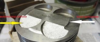
The intake manifold, or as it is popularly called the receiver, is a device that ensures a uniform flow of purified air into the cylinder head. The Priora receiver is subject to tuning and modifications, which we will talk about in this article.
In addition, the receiver accumulates air and smoothes out its vibrations, thereby ensuring smooth engine operation due to a uniform (without drops) supply of air masses. When the unit operates correctly, a highly saturated air-fuel mixture is supplied, and lower fuel consumption is achieved when the engine is running.
Reasons for replacing the Lada Priora receiver
There are a considerable number of varieties of intake manifolds, for example, made from various types of metals or composite materials. However, the Priora receiver is made entirely of plastic. This material prevents excessive heating of the manifold due to a hot car engine.
Thus, the air flow characteristics are improved, which has a positive effect on the proportions and quality of the air-fuel mixture. However, plastic also has a main, negative side - fragility. As a result, numerous breakdowns occur both due to the fault of the car owner and due to low temperatures at which the plastic loses its strength coefficient.
The most common damage can be caused by: - road traffic accidents (even minor ones); — accidental impacts during any repair work in the engine compartment; — other reasons;
If the receiver on your car has through holes or any other leaks, then it must be repaired (if possible) or replaced. If a part is faulty, air loss will occur, resulting in improper engine operation.
How to remove the receiver on a Priora
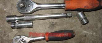
Tools that may come in handy: - 10mm socket; - key 13; - screwdriver.
To remove the intake manifold you will need:
- Due to the fact that in the next steps of the instructions there will be manipulations with electrical wiring, it is necessary to remove the negative terminal of the battery.
- The next step is to remove the plastic screen (cover) from the engine housing. This is done so that it does not interfere with your work.
- After which, it is necessary to remove power from the four ignition coils and dismantle them. To do this, pull out the contact chips. Take a 10mm socket (or a wrench of the same size) and unscrew one fastening bolt on each coil. Simply pull the coils upwards using the necessary force. Now they can be removed. There is no need to remove the spark plugs themselves; they will not interfere with removal. On the other hand, it is advisable to take advantage of the situation and check their condition (gap and spark quality).
Video “Replacing elements with plug-inless ones”
You can learn more about this process from the video.
Operations performed when replacing the intake manifold sealing rings on a VAZ 2170 2171 2172 Lada Priora
To seal the joint between the flanges of the cylinder head and the intake manifold, as well as between the flanges of the throttle assembly and the intake manifold, O-rings are installed in the grooves of the intake manifold pipes. If the tightness of these rings is broken, the engine runs unevenly (“troit”).
Tools required when replacing the intake manifold o-rings on a VAZ 2170 2171 2172 Lada Priora
You will need: screwdrivers with a flat and Phillips blade, wire cutters or a knife, keys “10”, “13”.
Installing a receiver on a Priora
As usual, installation is carried out in the same way as removal, however, during its production you must be extremely careful not to damage the receiver body. It is extremely important to insert the installed part with the holes into the connecting pins of the cylinder block, after which the manifold is directed to the mounting points on the engine.
Small but important points for installation:
- always clean or lubricate the rubber seals installed at the points of contact between the receiver and the cylinder block;
- Properly tighten the nuts at the joints of the elements.
Replacing the receiver on the Stinger in the Lada Priora
Finally got around to replacing the standard plastic receiver with a receiver from Stinger. I wanted to not just install a receiver, but take measurements and compare the results.
0:289
Installation:
Removing the standard receiver went fairly smoothly. I had to remove the generator, but I did this procedure last time and already installed the bottom bolt more conveniently, back to front.
0:635
1:1140
2:1645
Cone pipes
2:1676
3:2181
4:504
Fitting
4:524
Next, I tried on the new receiver, it didn’t want to stand on the heels, it rested against the generator bracket, so I had to work with an angle grinder.
4:760
5:1265
The Stingera receiver was not equipped with studs for attaching the throttle, but it was not possible to take them from the standard receiver; there was only one stud on it, and the second one was a bolt.
5:1587
6:2092
I had to make a stud from a suitable bolt.
6:95
7:600
I cut the HBO fittings into the free spaces. This time closer to the cylinders, as I was advised.
7:770
8:1275
When I started to pull the receiver into place, I discovered that the outer bolts were too long, they did not attract the edges, their washers rotated freely. I placed additional washers and groovers under them. When I started installing the generator, I discovered that it rested on one of the receiver's horns. There was no desire to remove the receiver again, so I left it like that, the generator is now attached only to the bottom bolt and tightened with a drive belt.
8:2067
9:504
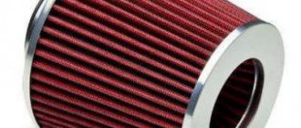
The next problem arose with the air filter housing; with the standard bellows it moved too far back, where there was no room for it at all. I managed to push it upside down and connect it through an old, cut corrugation from the nine.
9:927
10:1432
I couldn't get the oil dipstick into place even by bending the tube. I temporarily plugged the hole with a plug, and in the future I’m going to put a short 8kL probe there. Checking the oil level will now be very inconvenient.
10:1845
Comparison of results:
I took measurements of the Mass Air Flow and Cyclic Filling on the standard receiver and then on the Stingere. I decided to take not individual peak values, but average values in ranges of 500 rpm, I think this will be more accurate. The measurements were taken on different days, the weather was almost the same, but the position of the air filter housing and its air intake became different, I think this will introduce errors in the measurements.
10:2634
11:504
As you can see, there is an effect from the receiver, but only in the upper range, after 5000 rpm. At medium speeds, it turned out to be a failure. I feel satisfied, the car has become much faster at the top, the traction has become more uniform throughout the entire range (no catch in the middle and no dip at the end).
11:1019
Next, I want to do the same measurement on throttle 52, otherwise someone says that it is necessary to install it, someone says that it is of no use. I warn you right away that there are no questions about absolute digital values; we are only interested in relative results. But comparing numbers measured on different machines, at different times, with different mass air flow sensors is not correct.
11:1672
https://www.drive2.ru/l/993320/
11:1707 next article:
Transition to j7es firmware January 7.2 Lada Priora
The first valuable investment in a new car was the acquisition of normal brains, January 7.2 I can flash them myself,
12:2536
Rating 0.00 [0 Vote(s)]
17832
Which receiver is better for Priora?
There is no clear answer to this question. Each situation is individual. However, some comparisons can be made between receivers made of plastic and aluminum.
Advantages of aluminum products:
- higher strength and wear resistance;
- increased engine power due to design features and a larger volume of supplied air;
- Some models are easier to install and therefore easier to remove.
In addition, the shape of the collector itself plays an important role in ensuring increased power, which should not contain sharp corners and transitions. The most important difference between plastic and metal is the strength and durability of the latter. Therefore, we can recommend installing metal types of intake manifolds for Lada Priora cars.
Operations performed when replacing the cathode collector on a VAZ 2170 2171 2172 Lada Priora
The nuts securing the catalytic converter to the cylinder head are difficult to access. In addition, the collector flange is sealed with a metal-reinforced gasket. The sealing gasket must be replaced every time the connection is disassembled. Before removing the catalytic converter, it is necessary to remove the intake manifold - this will facilitate access to its mounting.
1. Remove the decorative engine casing (see “Removing and installing the decorative engine casing on a VAZ 2170 2171 2172 Lada Priora” ).2. Remove the wire from the negative terminal of the battery.3. Disconnect the exhaust pipe of the additional muffler from the exhaust manifold by unscrewing the nuts securing the intake pipe flange to the exhaust manifold flange and remove the exhaust pipe flange from the studs of the exhaust manifold flange (see “Replacing the additional muffler on a VAZ 2170 2171 2172 Lada Priora”). 4. Remove the air filter (see “Removing and installing the air filter on a VAZ 2170 2171 2172 Lada Priora”).
5. Remove the air supply hose and three hoses of the crankcase ventilation system (see “Cleaning the crankcase ventilation system on a VAZ 2170 2171 2172 Lada Priora”).
6. Disconnect the four connectors of the ignition module wiring harness and move the harness to the side. Remove the ignition modules (see “Removing and installing ignition coils on a VAZ 2170 2171 2172 Lada Priora”).
7. Remove the throttle assembly (see “Removing and installing the throttle assembly on a VAZ 2170 2171 2172 Lada Priora”).8. Remove the intake manifold (see “Replacing the cylinder head cover gasket on a VAZ 2170 2171 2172 Lada Priora”).
9. Disconnect the wiring harness blocks of the control and diagnostic oxygen concentration sensors from the engine harness...
10. ...and disconnect the holders of the wiring harnesses of the control and diagnostic oxygen concentration sensors from the heat-insulating shield of the steering mechanism.
11. Unscrew the three nuts securing the thermal insulation shield of the steering mechanism to the engine shield and remove the shield.
12. Unscrew the two nuts securing the water pump supply pipe bracket, unscrew the bolts securing the catalytic collector to its mounting bracket, unscrew the eight nuts securing the catalytic collector to the cylinder head and remove the catalytic collector. Disconnecting the catalytic converter from the cylinder head and its troubleshooting is described in detail in the subsection “Replacing the catalytic converter gasket on a VAZ 2170 2171 2172 Lada Priora”.
13. Remove the sealing gasket of the catenary collector from the cylinder head studs.
Warning: Be sure to replace the sealing gasket of the catalytic collector and inlet pipe with a new one every time you disassemble the connection.
14. Clean the flanges of the block head and catalytic collector from remnants of the old gasket and carbon deposits.15. Unscrew both oxygen sensors from the catalytic collector and install them on the new catalytic collector.
16. Install the cathode collector and all removed parts and assemblies in the reverse order of removal.
Useful tips To prevent the gasket from sticking and to improve its tightness, we recommend lubricating the gasket on both sides with a thin layer of graphite grease before installation. Lubricate the exhaust manifold mounting studs with graphite grease.
Replacing the sealing rings of the intake manifold of a VAZ 2170 Priora
- Repair manuals
- Repair manual for VAZ 2170 (Priora) 2004+.
- Replacing the intake manifold O-rings
To seal the joint between the flanges of the cylinder head and the intake manifold, as well as between the flanges of the throttle assembly and the intake manifold, O-rings are installed in the grooves of the intake manifold pipes. If the tightness of these rings is broken, the engine runs unevenly (“troit”).
You will need: screwdrivers with a flat and Phillips blade, wire cutters or a knife, keys “10”, “13”.
1. Lift the hood and disconnect the wire from the negative terminal of the battery.
2. Remove the decorative engine casing (see “Removing and installing the decorative engine casing” ).
3. Remove the throttle assembly from the intake manifold (see “Removing and installing the throttle assembly” ).
4. Remove the intake manifold (see “Replacing the cylinder head cover gasket” ).
| 5. Remove the inlet port O-rings. | 6. Use a screwdriver to pry... |
7. ...and remove the seal of the throttle assembly mounting flange.
8. Install new O-rings into the manifold grooves.
9. Before installing the intake manifold, cover the intake ports with a rag and clean the O-ring seats.
10. Install the removed parts in the reverse order of removal.
↓ Comments ↓
1. Car structure
1.0 Car structure 1.1 General information about the car 1.2 Passport data 1.3 Car keys 1.4. Controls 1.5. Heating and ventilation of the cabin 1.6 Ensuring a comfortable air temperature in the cabin 1.7. Doors 1.8. Passive safety equipment on the car 1.9. Seats
2. Recommendations for use
2.0 Recommendations for use 2.1. Safety rules and recommendations 2.2 Running in the car 2.3 Operating the car during the warranty period 2.4. Preparing the car for departure
3. Problems along the way
3.0 Malfunctions along the way 3.1. The engine does not start 3.2 Malfunctions of the fuel injection system 3.3 Idle speed has disappeared 3.4. Interruptions in the operation of the 3.5 engine. The car moves jerkily 3.6 The car accelerates poorly 3.7 The engine stalled while driving 3.8. Oil pressure dropped to 3.9. Engine overheating 3.10. The battery does not recharge 3.13. Knocks in the engine 3.16. Wheel puncture
4. Maintenance
4.0 Maintenance 4.1. General provisions 4.2. Inspection work 4.3. Lubrication and filling works 4.4. Diagnostic work 4.5. Repair and adjustment work
5. Engine
5.0 Engine 5.1 Design features 5.2 Possible engine malfunctions, their causes and solutions 5.3 Useful tips 5.4 Checking compression in the cylinders 5.5 Removing and installing the decorative engine casing 5.6 Removing and installing the engine splash guard 5.7 Installing the piston of the first cylinder to the TDC position of the compression stroke 5.8 Replacing the drive belt gas distribution mechanism and tension roller 5.9 Replacing the power unit supports 5.11. Replacing engine seals 5.13. Engine cylinder head 5.15. Engine repair 5.16. Lubrication system 5.17. Cooling system 5.18. Power supply system 5.19. Design Features
6. Transmission
6.0 Transmission 6.1. Clutch 6.2. Gearbox 6.3. Front wheel drives
7. Chassis
7.0 Chassis 7.1. Front suspension 7.2. Rear suspension
8. Steering
8.0 Steering 8.1 Design features 8.2 Possible steering malfunctions, their causes and solutions 8.3. Steering column 8.4. Steering linkage 8.5. Steering gear
9. Brake system
9.0 Brake system 9.1 Design features 9.2 Possible malfunctions of the brake system, their causes and solutions 9.3 Bleeding the brake system hydraulic drive 9.4 Removing and installing the vacuum brake booster 9.5 Replacing the brake pedal axle bushings 9.6. Main brake cylinder 9.7. Front wheel brakes 9.8. Braking mechanisms of the rear wheels 9.9. Pressure regulator 9.10. Brake hoses and tubes 9.11. Parking brake
10. Electrical equipment
10.0 Electrical equipment 10.1 Design features 10.2. Battery 10.3. Mounting block (relays and fuses) 10.4. Generator 10.5. Starter 10.6. Ignition switch (lock) 10.7. Electronic engine control system (ECM) 10.8. Ignition system 10.9. Lighting, light and sound signaling 10.10. Windshield cleaner 10.11. Washer reservoir 10.12. Electric fan of the engine cooling system 10.13. Electric motor of the heating and ventilation system fan 10.15. Cigarette lighter 10.16. Instrument cluster 10.18. Electronic anti-theft remote control system 10.19. Immobilizer 10.21. Replacing sensors and switches
11. Body
11.0 Body 11.1 Design features 11.2 Possible body malfunctions, their causes and solutions 11.3 Removing and installing windshield frame lining 11.4 Removing and installing soundproofing upholstery in the engine compartment 11.5. Removing and installing bumpers 11.6 Removing and installing the fender liner and protective wing cover 11.7 Removing and installing the front fender 11.8 Removing and installing decorative sill trims 11.9. Hood 11.10. Trunk lid 11.11. Doors 11.12. Seats 11.13. Seat belts 11.14. Rear view mirrors 11.15. Interior fittings 11.16. Instrument panel 11.17. Heater 11.20. Body care
12. Applications
12.0 Appendix 12.1 Appendix 1. Tightening torques of threaded connections, Nm 12.2 Appendix 2. Fuels, lubricants and operating fluids 12.3 Appendix 3. Nominal filling volumes 12.4 Appendix 4. Basic data for adjustments and monitoring 12.5 Appendix 5. Spark plugs used on vehicles 12.6 Appendix 6. Lamps used on a car 12.7 Appendix 7. What you need to have in a car 12.8 Appendix 8. Tools used when repairing a car
13. Electrical diagrams
13.0 Electrical Diagrams 13.1 Diagram 1. Instrument Panel Harness Connections 13.2 Diagram 2. Vehicle Front Wire Harness Connections 13.3 Diagram 3. Engine Electronic Control System (ECM) Harness Connections 13.4 Diagram 4. Vehicle Rear Wire Harness Connections 13.5 Diagram 5. Light Harness Connections license plate light 13.6 Diagram 6. Left front door wiring harness connections 13.7 Diagram 7. Right front door wiring harness connections 13.8 Diagram 8. Rear door wiring harness connections
Review of the exhaust system of Lada Priora
The exhaust gas exhaust system on the Lada Priora performs the following functions:
- exhaust gas removal;
- noise reduction when the engine is running;
- neutralization of toxic hazardous substances in exhaust gases.
The basis of the Priora exhaust system includes:
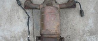
- 1. Exhaust manifold with converter;
- 2. Resonator;
- 3. Main muffler;
- 4. Auxiliary muffler;
- 5. Connecting pipes.
The manifold is used to remove exhaust gases from the cylinders into the exhaust pipe. The tightness of the connections is ensured by sealing with a metal gasket in two layers between the block head and the exhaust manifold. The attachment of the exhaust manifold to the cylinder head on one side goes into connection with the converter on the other. The collector and converter connected into one unit make it possible to reduce the warm-up time to the operating temperature of the latter, which significantly increases the efficiency of the converter.
Installation of oxygen concentration sensors at the inlet and outlet of the converter ensures constant monitoring of the quality of exhaust gases. The connection between the intake pipe and the manifold has a heat-resistant seal in the form of a metal-asbestos gasket. And the metal compensator connecting the additional muffler with the exhaust pipe serves as a vibration damper from the engine to the body and the entire exhaust system.
The exhaust gas exhaust system is connected by attaching it to the body brackets using 4 rubber rings. On the main muffler, the suspension cushion has a reinforced structure, which is due to the increased load on it.
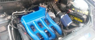
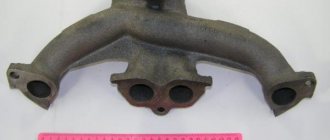
What is a “spider” for Priora and what is it for?
Tuning the exhaust system of the Lada Priora includes replacing the exhaust manifold with a similar sports version, which is called the “spider”. The main difference between the original manifold and the spider is that the latter has a larger diameter and the same length of outlet pipes, which facilitates the rapid release of exhaust gases from the cylinders to the exhaust pipe.
This spider design prevents exhaust gases from flowing back into the combustion chamber, which increases engine power and performance. In addition, the manifold performs the function of purging the combustion chamber and filling it with a combustible mixture due to the pressure that is created when exhaust gases are released.
To tune the Priora exhaust system, a ready-made kit for installing a direct-flow Stinger exhaust with additional components that are perfectly attached to each other is often used. As a rule, the tuning kit includes the following parts:
- new muffler with nozzle;
- spider;
- resonator Stinger Sport with a pipe diameter of 51mm.
The need to install a “spider” on Priora arises when:
- long vehicle acceleration time;
- low engine power;
- failure of the old exhaust system, where installing a spider on a Priora is considered as an alternative to the old one.
On the tuning parts market there are many modifications of “spiders” made by different manufacturers. Some models are produced without oxygen sensors, which requires reflashing the electronic engine control unit.
There are spiders with long and short pipes, which are indicated by the corresponding numbers 4-2-1 and 4-1. These designations reflect the shape of the spider pipes, that is, 4 pipes merge into 2, and then into 1, in the second option, respectively, 4 pipes are immediately combined into one, which significantly reduces the length.
The most popular among car enthusiasts has become the long spider 4-2-1, which, unlike the short one, shows good results in a wide speed range. A short spider 4-1 is better suited for forced engines operating at 6-10 thousand rpm.
Installation of “spider” 4-2-1 on Lada Priora: step-by-step instructions and price
To install a new spider collector, you will need:
- flat screwdriver;
- 13mm head with extension;
- WD-40 lubricant.
It is recommended to perform the work in the following sequence:
- 1. Remove the auxiliary muffler from the manifold by bending the edges of the plate and unscrewing the three mounting nuts on the pipe, after making sure that the Priora exhaust system has cooled down;
- 2. Remove the protective screen and locking plate;
- 3. Gradually disconnect the old factory manifold from the cylinder head. First of all, you need to separate the wire connectors from the oxygen sensors. Then unscrew the bolts securing it to the cylinder block and remove the bracket. Unscrew the eight nuts connecting the manifold and the block head and remove it;
- 4. Free the holes in the cylinder head from carbon deposits, lubricate the open studs with graphite lubricant;
- 5. Place the 4-2-1 spider on the open studs and reassemble the exhaust system in the reverse order;
- 6. Make sure that the spider does not come into contact with wiring and body parts, which can lead to their deformation due to strong heating.
Before installing a spider on a Priora, you should pay attention to the cost of this design. The price range for various modifications of spiders ranges from 2 to 7 thousand rubles, taking into account consumables and labor. The installation process takes no more than one hour.
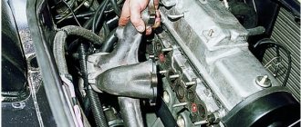
Intake manifold removal process
Replacing knock sensor Priora 16 valves
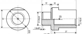
General view of the intake manifold
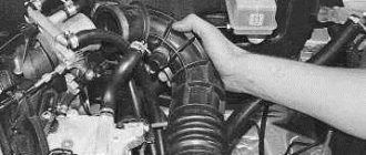
Dismantling the intake manifold is carried out with the car cooled down for safety reasons. So, this operation can take about an hour and will require some knowledge of the car’s design, namely the injection system. So, let's consider the sequence of actions for dismantling the unit:
- We dismantle the throttle. To do this, it is not necessary to disconnect all the pipes and pipes; it is enough to disconnect the unit from the manifold and move it to the side. Of course, at the same time, it is still recommended to remove the throttle valve completely for cleaning.
Location of the throttle valve on a VAZ-2112 - photo of an editorial car
Removed the wires and coil
Unscrew the clamp and disconnect the vacuum brake booster tube
Using a Phillips screwdriver, unscrew the oil level indicator guide tube
Unscrew the ignition coils and receiver
Unscrew the bolts securing the manifold to the block head
Pull the collector towards you and dismantle it
It is worth noting that installation of the intake manifold is carried out in the reverse order and does not require any additions or changes.
Dismantling the intake manifold of a 16-valve VAZ-2112 is quite easy and simple. Of course, it’s worth understanding at least a little about the design of the main power unit, but if desired, any car enthusiast can remove this unit.
carfrance.ru
Advantages and disadvantages of installing a spider on a VAZ 2170
After installing the “spider” on the VAZ 2170, Priora owners note the following positive changes in its operation:
- the car accelerates faster;
- the maneuverability of the car on the road improves;
- the engine sound is reminiscent of a sports car engine;
- the engine becomes more powerful up to 10 hp;
However, often a change in the design of the exhaust system associated with the installation of a spider can also have negative consequences:
Sooner or later, the car needs to be repaired. In some places the replacement must be carried out as planned, in others it is not. But every car owner faces a similar problem.
The question immediately arises: what repairs can you realistically carry out on your own, and where do you need to go to a car service center? Thanks to the Internet, all the necessary information, even with video instructions, can be found quickly.
The main function of the manifold is to distribute air among the engine cylinders, and also mix the fuel-air mixture there. And if you do not diagnose the operation of the air system in a timely manner and do not pay attention to the symptoms, this can lead to more serious engine damage.
Determining whether the engine is sucking in air
Before you start removing more than half the engine parts to get to the manifold, you should check other parts of the air system. And after that, carry out a complete tuning of the car. First of all, you need to inspect all the hoses and gaskets located on the cylinder block.
The most common method of finding air leaks is to spray the hoses with plain water; if there is a hole in one of them, the engine speed will decrease when water enters.
Detailed instructions for removing the intake manifold on a new Priora
It is necessary to remove parts from a cooled engine. It will take about an hour, provided that you have at least a little understanding of the injection system. The following sequence of actions must be followed:
- First of all, you need to remove the throttle. There is no need to completely remove it, just move the assembly connecting it to the manifold to the side. You also need to remove the throttle valve to thoroughly clean everything;
- disconnect the drive throttle cable from the manifold;
- disconnect the connectors from each other to remove the wires from the ignition coils;
- on the camshaft, disconnect the sensor wires;
- disconnect all canister wires;
- disconnect the brake booster vacuum hose going to the manifold;
- then unscrew the clamp and remove the ventilation pipe;
- Unscrew the self-tapping screw of the oil level indicator guide tube;
- remove the dipstick with the guide tube;
- using sockets and a ten-size wrench, unscrew the nuts and bolts securing the exhaust module and coils from cylinders 1-2-3;
- remove the coils;
- then you need to unscrew the collector fasteners;
- slide it forward and remove the manifold.
Removing and installing the intake manifold
| GENERAL INFORMATION |
Pontiac Trans Sport
Fuel Injection Harness Connectors
| The wiring harness connector is indicated by the arrow. |
Places for applying sealant to mating surfaces
| The places where the sealant is applied are indicated by arrows. |
Removing the fuel line and injection valves from the manifold
| The injection valve is indicated by an arrow. |
ONS ENGINES
EXECUTION ORDER
1. Remove the ground wire from the battery.
2. Drain the coolant. 3. Disconnect the vacuum tubes from the manifold. The number of tubes depends on the model and equipment.
4. Remove the fuel injector harness connectors at the end of the pipeline closest to the bulkhead.
5. Disconnect the oil pressure warning light sensor wire under the manifold.
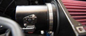
6. Loosen the clamps and remove the line, air flow meter and pipeline from the manifold.
7. Remove the distributor cover and disconnect the high-voltage wires.
8. Unscrew the two nuts and remove the support that runs from the manifold to the right side of the cylinder head.
9. Unscrew the four bolts and remove the support that connects the manifold base to the left side of the block.
10. Unscrew the accelerator cable bracket and move it to the side.
11. Disconnect the fuel supply pipe from the fuel bracket and the return pipe from the fuel pressure regulator.
12. Disconnect the cooling system hose from the manifold.
13. Unscrew the six nuts and bolts securing the manifold (indicated by arrows) and remove it. A ground wire can be connected to one of the studs with an additional nut.
14
Carefully remove the manifold together with the connecting parts from the cylinder head. If the distributor interferes with removal, unscrew the front manifold stud or remove the distributor.
15
Remove the gasket from the cylinder head.
16. Installation is carried out in the reverse order of removal. Apply a layer of sealant to the mating surfaces.
DONS ENGINES
| EXECUTION ORDER |
| 1. Remove the ground wire from the battery. |
| 2. Drain the coolant. |
| 3. Disconnect the cooling hoses from the thermostat housing and the intake manifold. |
| 4. Disconnect the air intake pipe from the front of the intake manifold. |
| 5. Disconnect the crankcase ventilation hoses and vacuum hoses from the intake manifold. |
| 6. Disconnect the accelerator cable. |
| 7. Remove the high-voltage wires from the spark plugs and move them to the side. |
| 8. Disconnect the wires from the radiator fan switch, engine coolant temperature sensor and temperature sensor. |
| 9. Remove the throttle position sensor connector. |
| 10. Remove the fuel injectors. |
| 11. Unscrew the 10 bolts and 2 nuts securing the manifold to the cylinder head and carefully remove the intake manifold. Remove the gasket. |
| 12. Remove the 2 plastic spark plug gaskets from the socket in the cylinder head. |
| 13. Installation is carried out in the reverse order of removal. Pour liquid into the cooling system and check the idle speed and CO content. |
V6 ENGINES Coolant outlet connection on the intake manifold of a V6 engine
Procedure for tightening the intake manifold bolts on V6 engines
| EXECUTION ORDER |
| 1. Remove the ground wire from the battery. |
| 2. Drain the coolant. |
| 3. Remove the throttle lever cover. |
| 4. Loosen the clamps and move the air flow meter-collector line to the side. |
| 5. Remove the crankcase ventilation hose. |
| 6. Remove the upper radiator hose and heater hose from the outlet on the front of the pipe. |
| 7. Disconnect the connectors from the idle speed valve, temperature sensor, coolant temperature sensor and throttle position sensor. Disconnect the fuel injector wiring harness. |
| 8. Disconnect the accelerator cable from the lever. On models with automatic transmission, also disconnect the kick-down cable or connector. |
| 9. Disconnect the fuel supply and return pipes. |
| 10. Remove the high-voltage wires and the ignition distributor. |
| 11. Unscrew the eight bolts and remove the overpressure chamber. |
| 12. Unscrew the seven bolts and remove the cylinder head covers. |
| 13. Disconnect the water pump bypass hose from the intake manifold. |
| 14. Unscrew the eight bolts and remove the intake manifold. |
| 15. Remove the intake manifold along with the pressure regulator, fuel bracket and throttle body housing. |
| 16. Installation is carried out in the reverse order of removal. Apply a layer of sealant to the mating surfaces. |