April 20, 2017 Lada.Online 185 927 65
If, while operating a LADA car, you notice that during load (when the air conditioner is running, the heating is on, etc.) in a traffic jam, the engine begins to operate unstably (troits, pulls poorly, etc.), perhaps the reason lies in the ventilation system crankcase The article proposes to solve the problem by installing a PCV valve from a foreign car.
Cons of SVKG in Lada Priora
By cleaning the atmosphere from the emission of toxic substances, SVKG creates problems for the engine. The gases that are removed from the pan, despite the presence of an oil separator, are saturated with microscopic oil particles, which after some time leads to contamination of the fuel intake system.
This leads to engine interruptions. Gas particles settle on the valve components, which leads to its failure. This disrupts the fuel injection system into the combustion chamber and increases oil consumption. If contamination is severe, fuel injection does not occur. In this case, the valve must be completely replaced. It is necessary to periodically inspect the crankcase ventilation hoses, because under the influence of the environment they age and crack.
If you detect oil stains, an increase in the amount of oil consumption, an increase in the consumption of fuel and lubricants, as well as disturbances in the engine (stopping, does not start for a long time, makes exhaust and other uncharacteristic sounds), be sure to immediately contact a service center to have the engine checked and repaired. Timely treatment will reduce the cost of engine repairs and prolong its operation.
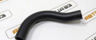
Hi all! Today we will talk about a small, but extremely useful modification! And so, I recently came across a blog post from a friend about installing a certain PCV valve, and yesterday I accidentally mentioned this topic to my friends. And they told me that there is just such a valve and they can fit it for me :) The valve was purchased for a Honda Integra. He looks like this
As a result, the entire internal volume of the engine will work as a parallel receiver of very significant volume, connected to the intake, bypassing the throttle. It is this volume that will interfere with the formation of a high-quality mixture. A similar situation occurs in a traffic jam when driving in tension with additional consumers (for example, the air conditioner is on). And so this afternoon I went to the garage and started installation.
I had to struggle with the hoses, since the valve is thin on one side and thick on the other, so I had to use a 10mm hose, fortunately it was left after installing the oil trap.
Results. Effect:
I want to say that I am again indignant at what %;" I didn’t find out about this thing earlier?!)) Now the car’s dips in 1st and 2nd gears have decreased, when the air conditioning is turned on, the dullness has decreased, the car has begun to feel better at low speeds in 2nd and 3rd gears. I really felt everything that I wrote personally, as I rode all day and evening, everything was tested in traffic jams and in the heat
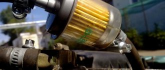
Replaced the breathers. I modified the first circuit with a regular Nevsky fuel filter. I didn’t use sealant, I don’t see the need.
A little theory
(about the operation of two gas filtration circuits):
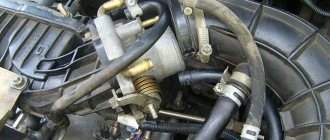
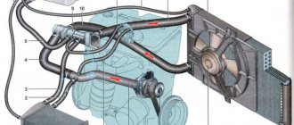
These are two crankcase ventilation circuits. the hoses of the first and second circuits are two additional hoses (one of small diameter, the other of large diameter), through which crankcase gases, having passed the oil separator, are supplied to the combustion chamber through the throttle pipe. The oil separator is located in the cylinder head cover.
The first circuit has a calibrated hole (nozzle) in the throttle pipe. A small diameter hose goes from the oil separator to the nozzle. A larger diameter hose (secondary circuit hose) goes from the oil separator to the intake pipe hose (over-throttle space).
At idle, all crankcase gases are supplied through the primary circuit nozzle (small diameter hose). In this mode, a high vacuum is created in the intake pipe and crankcase gases are effectively sucked into the after-throttle space. The jet limits the volume of sucked gases so that engine idle operation is not disrupted.
Under load conditions, when the throttle valve is partially or fully open, a small amount of crankcase gases passes through the primary circuit nozzle. In this case, their main volume passes through the second circuit (large diameter rod) into the intake pipe hose in front of the throttle pipe and is then burned in the combustion chamber.
Diagram of the standard crankcase ventilation system
The crankcase ventilation system of VAZ engines consists of two circuits that operate at different load modes and speeds:
- The small ventilation circuit is connected to the valve cover and the intake manifold (behind the throttle body). This connection diagram provides intensive crankcase ventilation due to the vacuum that occurs in the intake manifold when the throttle is closed. To avoid an effect such as hyperventilation, the cross-section of the small circuit is limited by a jet in the cable throttle body with a diameter of 1.7 millimeters. This circuit operates in the region of 800-1500 rpm.
- A large ventilation circuit is connected to the valve cover and the air pipe (in the pre-throttle space). This scheme provides intensive crankcase ventilation at high speeds. The cross section of the large contour is 16-18 millimeters
Examples demonstrating the shortcomings of the standard crankcase ventilation system:
- A car is going down a hill with the gear in gear. In this mode, the engine operates at higher speeds with a reduced load. A high vacuum is created in the crankcase, and a large ventilation circuit is connected, in which there are no control valves. Since both circuits are connected to one volume of the oil trap, a strong vacuum in the crankcase will draw a fresh portion of air bypassing the throttle. The mass air flow sensor will show increased air flow, and the ECU will try to close the throttle. Having realized that this is not possible (it is already closed), the lean mixture will be corrected by increasing the fuel supply (fuel consumption will increase). As a result, the entire internal volume of the engine will work as a parallel receiver of very significant volume, connected to the intake, bypassing the throttle. It is this volume that will interfere with the formation of a high-quality mixture.
- A car in a traffic jam drives under tension with additional consumers (for example, the air conditioner is on). The compressor clutch is connected, the load increases abruptly. The engine does not have enough air, it begins to pull it from the crankcase, bypassing the throttle. But the ECU is also aware of the clutch engagement and also supplies more air by opening the throttle. The vacuum drops sharply, the vacuum brake booster (VBR) does not have enough strength to hold the car. Leap forward. The ECU sees an increase in oxygen and closes the throttle. A sharp increase in vacuum, VUT seizes. The car jerks, the transmission hits. And so on ad infinitum.
As a result, in both cases, when the engine is running, speed jumps occur and the engine choke under the load. Jerking and vibration are possible on manual transmissions, automatic transmissions and automatic transmissions. To eliminate these shortcomings, it is proposed to modify the design according to one of the presented schemes.
Cleaning SVKG in Lada Priora
After prolonged use, gas deposits accumulate in the crankcase ventilation system. This deposit makes it difficult for gases to pass into the cylinders. As a result, the gas pressure in the engine increases, which leads to oil leakage. Timely cleaning of the SVKG will help prevent this. The manufacturer of Lada Priora recommends carrying out this procedure after every 60 thousand kilometers. This service manipulation can be performed in a car workshop or independently.
To do this, you need to have tools (narrow pliers, 8mm nut wrench, Phillips screwdriver).
When cleaning the SVKG yourself, you need to perform the following steps:
- Remove the decorative engine cover.
- Remove the air filter.
- Carefully loosen the clamp on the ventilation hose clamp on the engine.
https://youtube.com/watch?v=XHfJxvd_5Ec
While the engine is running, it is prohibited to break the tightness of the SVKG, as well as to remove the oil filler cap.
This will lead to the release of toxic substances into the environment and disruption of the crankcase.
Let's sum it up
Taking into account the above, it becomes clear that an increase in crankcase gas pressure and oil leakage through the breather indicate a number of problems with the breather or internal combustion engine. Quick detection and elimination of faults will reduce the cost of repairing the power unit. This is true if the problem is eliminated at an early stage, that is, without the consequences that arise after a long period of ignoring the malfunction and further active operation of the engine.
Finally, we note that quite often heavy oil leaks through the breather do not appear immediately. In other words, the lubricant may leak slightly, which is sometimes unnoticeable. In other cases, about 0.5 or a liter of lubricant can escape through the breather from the lubrication system, taking into account a short mileage (on average, 1-3 thousand km). With such a significant leak, the operation of the internal combustion engine is stopped, diagnostics and repairs are carried out.
What malfunctions are indicated by the emulsion on the oil dipstick and oil filler cap? Ways to independently determine the causes of this problem.
Lada Priora Station Wagon Roach 2WD › Logbook › PCV valve.
I feel like I’ll publish this material a little later. Today is January 10, 2018
and I just picked up all the parts from the store. There is still installation and testing ahead.
So! A month ago I came across a very interesting article by comrade IgorRV about modernizing the crankcase ventilation system. It was described in detail, I decided to try making it myself.
And then there was a note (and another note) by comrade kulibin2004, after reading which my ardor died down somewhat.
But alas! I am constantly drawn to adventure, so I decided to check the feasibility of this valve personally.
The canonical instructions indicate General Motors valve 94580183. It is also recommended to pay a little more and install valve 2674021314 HYUNDAI/KIA. The first is in a plastic case, the second is metal. I took the second one.
I’ll just remove the old hose with the jet, I won’t cut it. Suddenly you want to return it back... I took the additional crankcase ventilation hose (BRT) from the VAZ-2123. Plus 4 clamps.
When assembling, the main thing is not to screw up the direction of the valve.
Added 01/11/2018.
Collected. Nothing special, just -8 outside, my hands were freezing, it was dark, and the phone I was using was dead exactly when I had already removed the old hose and was getting ready to install a new one. There was enough hose to spare.
I started it right away and reset the average consumption to zero. I turned on the heated rear window - the speed dropped, as usual. There may be differences, but they are minimal.
Let's go. First I taxied around the yard, in first gear. You immediately feel MUCH smoother and more elastic engine operation. At low speeds it works noticeably more pleasantly. Starting from a traffic light again became noticeably better. I’m not ready to say that cravings have increased. If so, it will be insignificant. But the jerking and twitching went away. Yes, the most important thing! The delay between pressing the gas and increasing the speed has completely disappeared. At first it was just wildly pleasing, but I quickly got used to it - after all, everything became the way it should be. And if one can argue with the presence/absence of an increase in low-end traction and elasticity (softness) (because taste in general is an asshole), the result here is obvious.
And I was almost ready to say that the improvement had paid off. But! Fuel consumption. I reset it, but somehow I didn’t control it. In the morning I come to the parking lot, start it, turn on the heated rear window, go sweep away the snow while the engine warms up. As soon as it warmed up to 50 degrees, I was ready to go. I checked the average consumption, and it was 22 liters/100 km! Shock and horror! I’m ready to chalk it up only to the fact that I’ve driven 5 kilometers since resetting, plus warmed it up in the morning. While driving to work (20 minutes, city mode, no traffic jams), the average consumption dropped to 14 liters/100 km. All the same - atas... I'll see what happens next. With all this, the driving experience is excellent, it really works great! Soft, smooth - a sight for sore eyes!
Added 01/16/2018.
The average consumption is gradually decreasing. I only drove around the city. By the weekend it turned out to be 11.4. On the weekend I drove around the city as usual, plus to the ski resort (through the whole city). With traffic jams. The average consumption is 9.8. With the beginning of the new work week, the consumption rose to 10.3. Previously, under similar conditions, it was about 12-13. It seems that everything is too good to be true... All that remains is to check on the track. But that's in two weeks.
The average flow rate increases (and noticeably) during warm-up. Now it’s winter, I heat the coolant to 50 degrees, there’s no blanket, I don’t close the radiator. 20 minutes to work, around the city. That is, the conditions for measurements are not the most favorable for obtaining beautiful values. I turn on the stove only after warming up.
Added 01/22/2018.
Another week of urban regime. 11.4 liters by the end of the working week. On the weekend I drove around the city and went to the ski resort. The weather is snowing (it’s been falling for 24 hours), nothing has been cleared, that is, the consumption must obviously be high. However, by Sunday evening it drops to 10.1. Just like that. You heat less, you drive more.
Added 01/28/2018.
So, I drove 325 km along the highway. 24 liters. 7.3 per hundred. At the same time, I drove the return half in a strong snowstorm. It has been snowing for two days now, the entire route is covered, the temperature is -13, -15 degrees. That is, the consumption in such weather is clearly increased. The speed is 90-120. The same consumption was achieved in the summer at obviously higher speeds. And now it’s snowing—there’s no clear comparison. In the summer I’ll compare them completely.
Bottom line.
In the meantime, I'm happy with the new thing. The most important thing is that I feel more comfortable driving. No gas pedal lag, smoother operation. The consumption doesn’t disappoint. I installed it for myself and I recommend you try it. Fortunately, it is available.
Used:
1. VALVE-PCV valve Hyundai / KIA. Article: 2674021314. 318 rubles.2. VAZ-2123 crankcase ventilation hose additional BRT. Article: 2123-1014240. 90 rubles.3. Worm clamps, 4 pcs. 4x25=100 rubles.
Cleaning SVKG in Lada Priora
After prolonged use, gas deposits accumulate in the crankcase ventilation system. This deposit makes it difficult for gases to pass into the cylinders. As a result, the gas pressure in the engine increases, which leads to oil leakage. Timely cleaning of the SVKG will help prevent this. The manufacturer of Lada Priora recommends carrying out this procedure after every 60 thousand kilometers. This service manipulation can be performed in a car workshop or independently.
To do this, you need to have tools (narrow pliers, 8mm nut wrench, Phillips screwdriver).
When cleaning the SVKG yourself, you need to perform the following steps:
- Remove the decorative engine cover.
- Remove the air filter.
- Carefully loosen the clamp on the ventilation hose clamp on the engine.
- Remove the crankcase ventilation hose (CVH) from the air supply sleeve.
- Loosen the clamp on the air supply sleeve.
- Disconnect the air vent hose from the throttle assembly.
- We loosen the clamp of the clamp and disconnect the ShVK of the large branch from the cylinder head cover (cylinder head).
- Using the same actions, we remove the small branch shvk, disconnecting it from the cylinder head cover and the throttle fittings.
- Loosen the clamp of the inlet ShVK clamp.
- We remove the supply ventilation hose and remove it from the cylinder head cover.
- Disconnect the supply ventilation hose from the cylinder head pipe.
- We wash all the hoses with gasoline, blow them out and dry them with a hairdryer. We also clean and dry all pipes and hose connections.
- Unscrew the cylinder head cover.
- We remove the separator by tightening its fastening in the form of 6 bolts, which are located inside the cylinder head cover.
- Using pliers, squeeze the oil deflector clamps and pull it out.
- Using a screwdriver, pull out the ring-shaped rubber seal. If it has lost its shape, then replace it with a new one.
- We clean the cylinder head cover and all mating surfaces from the sealant and degrease it with gasoline. Before installing the cylinder head cover, apply new sealant.
- We assemble the SVKG in reverse order.
https://youtube.com/watch?v=XHfJxvd_5Ec
This will lead to the release of toxic substances into the environment and disruption of the crankcase.
Removing and replacing the Priora oil pump
This operation must be carried out either in an inspection pit or on a special lift, unless, of course, you remove the engine from the Priora. So the process begins.
First of all, all the oil from the pan must be drained into a substitute container by unscrewing the pan plug. Unscrew the mounting bolts and remove the pan. Using the “8” key, unscrew the oil intake mount and remove it.
Use a No. 5 hex to remove the timing belt cover. Unscrew the damper. After squeezing the rollers, remove the belt from the crankshaft gear. Remove the gear itself. Remove the key from the crankshaft. Carefully wipe all surfaces with a rag and unscrew all six mounting bolts of the Priora oil pump housing.
After this, carefully pry up the unit housing and remove it from the crankshaft along with the gasket. Now all that remains is to replace the Priora unit. Clean the seat on the block and wipe with a rag.
Install a new gasket on the unit prepared for replacement and assemble in reverse order. Fill with the recommended oil and start the engine. Wait until the oil pressure warning lamp goes out. That's it, the Priora oil pump has been replaced.
In the video, removal and disassembly of the VAZ-2112 oil pump and modifications. Replacing a unit on a Priora is similar:
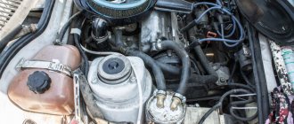
Where is the engine breather located?
From engine to engine, different car manufacturers may place the breather in different places. But in most cases it is located on the valve cover, next to the filler neck. Although there may be options: it is better to clarify in the description instructions for the car or find out on thematic forums.
In the picture on the right is the crankcase ventilation system of the VAZ 2111 engine, which includes a breather:
- Crankcase.
- Breather.
- Hose from the breather to the valve cover pipe.
- Oil separator under the valve cover.
- A thin hose from the valve cover to the fitting with the throttle body nozzle.
- Fitting with jet on the throttle valve block.
- Thick hose from the valve cover to the intake pipe..
But the breather is installed not only in internal combustion engines. It is in:
- Gearbox. Otherwise, the gearbox would begin to operate jerkily, and the wear of the gears on the secondary shaft would increase many times over. Something similar is observed when the breather becomes clogged and ceases to perform its function.
- If the design of the car provides for a separate transfer case, then a similar mechanism may be in it.
- Front, and in rear-/all-wheel drive vehicles - in the rear axle. Moreover, this inconspicuous detail not only equalizes pressure, it protects the mechanisms from dirt and moisture when overcoming water obstacles.
However, even their appearance is often similar, and often identical: they perform the same function.
see also
- Priora crankcase ventilation 16 valves
- Installation of industrial ventilation
- Ventilation of the hive in omshanik
- Installation of asbestos pipes for ventilation
- Fresh air ventilation
- Silencer for ventilation
- Ventilation engineering companies
- Ventilation for hood
- Fire ventilation valve
- In the state, breathing increases significantly and pulmonary ventilation increases
- Design of a ventilation system for a public building
VAZ 2170 | Cleaning the crankcase ventilation system
Over time, tarry deposits from crankcase gases accumulate in the engine crankcase ventilation system, making it difficult to remove these gases into the engine cylinders for combustion. Because of this, the gas pressure inside the engine increases and oil leaks through the seals appear. To avoid this, periodically clean and flush the system.
| HELPFUL ADVICE Clean the crankcase ventilation system before each oil change. |
You will need: a screwdriver, a 13mm wrench, kerosene for washing, clean rags, a container for washing parts.
| 1. Loosen the clamps securing the main hose to the breather cover and... | 2. ...additional hose to the air pipe and remove the hoses from the fittings of the cover and the pipe. |
| 3. Unscrew the breather cap nut and... | 4. ...remove the breather cap along with the additional hose and oil level indicator (dipstick). Remove the pointer from the cover guide tube. |
| 5. Wipe the internal cavity of the oil separator with a rag moistened with kerosene, preventing kerosene from entering the engine crankcase. |
| NOTE The oil separator mounting nut is difficult to access without a special tubular wrench. If there is no such key, clean the oil separator without removing it from the engine. If a large amount of kerosene gets into the engine crankcase when cleaning the oil separator, replace the oil in the crankcase. |
| 6. Rinse the system hoses and breather cap with kerosene. |
| 7. Inspect the breather cover gasket. Replace a torn or heavily compressed gasket. |
| 8. Reassemble the system in the reverse order of disassembly. |
Diagnosing the cause of oil rush
Since there are a large number of reasons for oil leaking through the breather, a comprehensive check of the engine is necessary to determine exactly why the problem arose.
At the same time, to carry it out, you don’t even need to disassemble the power plant, it’s just enough to take measurements of some parameters, as well as visually assess the condition of the ventilation.
For example, let's take the already mentioned VAZ-2110. Let's assume that in the engine of this car, plaque and oil deposits were noticed in the intake manifold, which indicates oil leakage through the breather.
To determine what caused this problem, you will need little - a set of open-end wrenches, a screwdriver, a compression gauge.
We'll start the test by assessing the exhaust gases. To do this, just start the engine and look at their color shade.
If it is gray or black in color, this indicates oil getting into the cylinders due to wear or sticking of the CPG rings or problems with the timing belt. Only this can help determine the cause; read more here - the causes of smoke from the exhaust pipe.
Schemes for upgrading the crankcase ventilation system
Schemes for modifying the crankcase ventilation system, as well as a description, are provided by IgorRV.
For LADA cars with manual transmission and AMT (“robot”), scheme No. 1 “Crankcase ventilation scheme with PCV valve for E-GAS and cable throttle” is suitable:
It is necessary to install a PCV valve (article 94580183, price about 400 rubles) from a foreign car into the small crankcase ventilation circuit. When connecting the PCV valve to a small circuit on an E-GAS, use a new hose (petrol-oil-resistant 8 mm without fabric reinforcement). On a cable choke, connect to the receiver, not to the choke.
As a result, the valve will shut off the circuits in transient modes, which will allow:
- Accept the load without jerking or dropping engine speed (for example, when the compressor is running, heated windows, seats, etc.).
- Reduce vibration load at idle
- Increase traction from the bottom (noted by owners of automatic transmission with VAZ-21126 engine, manual transmission with VAZ-21227, 21126 and 11186 and AMT with VAZ-21127).
- Get a sharper response to the gas pedal and faster shifts (on AMT). Perhaps due to the fact that the valve does not allow the engine to slow down, maintaining a more optimal switching algorithm.
- Reduce oil consumption through ventilation.
The valve replacement period is 40,000 km.
For LADA cars with automatic transmission (Jatco) and AMT (“robot”), scheme No. 2 is suitable:
Description of scheme No. 2: The pressure reducing valve is connected in series to a large ventilation circle. Thus, it regulates the flow of crankcase gases at high speeds and during transient processes. This allows:
- Exercise full control over the flow of crankcase gases between the small and large circuits.
- Improve engine operating mode.
- Reduce vibration load.
- Reduce oil release into ventilation.
For LADA cars with automatic transmission (Jatco) and AMT (“robot”), scheme No. 3 is suitable:
Description of scheme No. 3: To improve the operation of the braking system and facilitate the process of holding the car on the brakes in mode “D”, an “Ejection Pump” was used. Due to the flow of crankcase gases from the small circuit, the vacuum in the tube leading to the vacuum booster increases. This happens at low speeds, which is very helpful when driving in traffic jams. Keeping your foot on the brake all the time is not very easy, but this pump makes the task easier.
- Getting rid of vibrations, failures, transmission shocks.
- The engine begins to operate more calmly and softly.
- The force on the brake pedal becomes less.
- The air conditioner turns on almost imperceptibly.
- ejection pump (article 10793 VIKA, price 546 rubles);
- pressure reducing valve (article 1117701500 JP GROUP, 422 rubles);
- PCV valve (article 94580183 GENERAL MOTORS, 400 rubles);
- clamps (about 10 pieces, 600 rubles);
- thin, petrol-resistant 8 mm hose 50 cm (100 rubles);
- standard ventilation pipe.
Installation example on video:
By the way, there are other ways to modify the crankcase ventilation system. Are you ready for such modernizations? Let us remind you that modification of the ignition system (installation of capacitor ignition coils in the harness) is also common among owners of LADA cars.
Priora crankcase ventilation system 16 valves
The power plant of any car is a very complex device, including mechanisms and systems that interact with each other. At the same time, the engine is not a closed hermetically sealed circuit and it also has ventilation.
Crankcase ventilation is a scheme that ensures the removal of gases from internal cavities.
The fact is that during combustion of the working mixture in the cylinders, exhaust gases are formed, which are under pressure, due to which part of them penetrates into the sub-piston space - the crankcase, where it mixes with oil mist and moisture formed as a result of condensation.
This whole mixture is called crankcase gases.
Based on this, it follows that the main task of the ventilation system is to maintain pressure inside the engine and prevent it from exceeding the permissible norm by removing crankcase gases.
Schemes for upgrading the crankcase ventilation system
Schemes for modifying the crankcase ventilation system, as well as a description, are provided by IgorRV.
For LADA cars with manual transmission and AMT (“robot”), scheme No. 1 “Crankcase ventilation scheme with PCV valve for E-GAS and cable throttle” is suitable:
It is necessary to install a PCV valve (article 94580183, price about 400 rubles) from a foreign car into the small crankcase ventilation circuit. When connecting the PCV valve to a small circuit on an E-GAS, use a new hose (petrol-oil-resistant 8 mm without fabric reinforcement). On a cable choke, connect to the receiver, not to the choke.
As a result, the valve will shut off the circuits in transient modes, which will allow:
- Accept the load without jerking or dropping engine speed (for example, when the compressor is running, heated windows, seats, etc.).
- Reduce vibration load at idle
- Increase traction from the bottom (noted by owners of automatic transmission with VAZ-21126 engine, manual transmission with VAZ-21227, 21126 and 11186 and AMT with VAZ-21127).
- Get a sharper response to the gas pedal and faster shifts (on AMT). Perhaps due to the fact that the valve does not allow the engine to slow down, maintaining a more optimal switching algorithm.
- Reduce oil consumption through ventilation.
The valve replacement period is 40,000 km.
For LADA cars with automatic transmission (Jatco) and AMT (“robot”), scheme No. 2 is suitable:
Description of scheme No. 2: The pressure reducing valve is connected in series to a large ventilation circle. Thus, it regulates the flow of crankcase gases at high speeds and during transient processes. This allows:
- Exercise full control over the flow of crankcase gases between the small and large circuits.
- Improve engine operating mode.
- Reduce vibration load.
- Reduce oil release into ventilation.
For LADA cars with automatic transmission (Jatco) and AMT (“robot”), scheme No. 3 is suitable:
Description of scheme No. 3: To improve the operation of the braking system and facilitate the process of holding the car on the brakes in mode “D”, an “Ejection Pump” was used. Due to the flow of crankcase gases from the small circuit, the vacuum in the tube leading to the vacuum booster increases. This happens at low speeds, which is very helpful when driving in traffic jams. Keeping your foot on the brake all the time is not very easy, but this pump makes the task easier.
- Getting rid of vibrations, failures, transmission shocks.
- The engine begins to operate more calmly and softly.
- The force on the brake pedal becomes less.
- The air conditioner turns on almost imperceptibly.
- ejection pump (article 10793 VIKA, price 546 rubles);
- pressure reducing valve (article 1117701500 JP GROUP, 422 rubles);
- PCV valve (article 94580183 GENERAL MOTORS, 400 rubles);
- clamps (about 10 pieces, 600 rubles);
- thin, petrol-resistant 8 mm hose 50 cm (100 rubles);
- standard ventilation pipe.
SVKG device in Lada Priora
In all brands of cars, the SVKG is built on a similar principle. Only small details differ. On the upper side of the crankcase there is an oil separator, which looks like a hollow plug. An oil deflector is placed under the plug, which is designed to clean the gases from the crankcase as much as possible from oil particles. The oil separator has an outlet for the crankcase ventilation hose.
Features of ventilation design, operating principle
The simplest diagram of the crankcase ventilation system used on internal combustion engines previously consisted of only one fitting - a breather installed in the crankcase.
This breather connected the internal cavity of the cylinder block with the external environment, and crankcase gases simply escaped through it into the atmosphere.
But this scheme had one significant drawback - the exhaust gases contained oil particles, which also entered the external environment. And this is not only loss of lubricant and the need for periodic refilling, but also air pollution.
On modern cars the ventilation system is closed. It also has a breather, but a pipe is connected to it, allowing gases to be vented into the intake manifold or air filter housing, from where they enter the cylinders and burn. That is, the atmosphere is not polluted by them.
Additionally, the system includes elements that ensure oil separation and return back to the crankcase so that it does not enter the cylinders along with the gases.
There are several options for oil separators, and on cars from different manufacturers they may differ in design and operating principle.
It is worth noting that part of the exhaust gases enters the supra-valve space, and they must also be removed.
Therefore, the entire circuit of the engine ventilation system on a modern car consists of a breather, an oil separator and two pipes.
Additionally, a special valve can be included in the system to regulate the pressure of gases entering the intake manifold.
The configuration of the system can be very different, but this does not change its purpose and operating principle. For example, consider the ventilation design of the VAZ-2110.
At the bottom of the cylinder block of this car there is a breather, onto which a pipe is attached; the second end of this hose is connected through a fitting to the cylinder head cover. At the same time, an oil separator is located inside this cover at the inlet of the pipe.
On its other side there is another fitting, to which a tube is connected that goes to the air inlet pipe.
The principle of operation of such ventilation is simple - gases enter the cylinder head cover space through the breather and pass through the oil separator, while the separated oil flows to the valve assembly.
After this, the gases are mixed with those that have broken into the supra-valve space and are supplied to the air pipe, and then to the manifold. There is no pressure regulating valve in this car.
On other machines, the oil separator may be located immediately next to the breather, and a valve is installed behind it.
Article: 2112-1014056, additional articles: 2112-1014056Р
Order code: 006580
- Buy with this product
- show more
- Passenger cars / VAZ / VAZ-21101 drawing
- » href=»/catalog/vaz-3/legkovye_avtomobili-30/vaz_2110-10/sistema_smazki_i_ventilyacii-105/#part40486″>Lower hoseEngine / Lubrication and ventilation system
- Passenger cars / VAZ / VAZ-21121 drawing
- » href=»/catalog/vaz-3/legkovye_avtomobili-30/vaz_2112-12/sistema_smazki_i_ventilyacii-105/#part49102″>Lower hoseEngine / Lubrication and ventilation system
- Passenger cars / VAZ / Lada Priora 21701 drawing
- » href=»/catalog/vaz-3/legkovye_avtomobili-30/lada_priora_2170-480/sistema_smazki_i_ventilyacii-77/#part1578912″>Lower hoseEngine / Lubrication and ventilation system
- Passenger cars / VAZ / Lada Kalina 2192, 21941 drawing
- » href=»/catalog/vaz-3/legkovye_avtomobili-30/lada_kalina_2192__2194-1646/sistema_smazki_i_ventilyacii-56/#part3652972″>Lower hoseLubricating system / Lubrication and ventilation system
- Passenger cars / VAZ / Lada Kalina 21941 drawing
- » href=»/catalog/vaz-3/legkovye_avtomobili-30/lada_kalina_2194-1886/a501__sistema_smazki_i_ventilyacii-130/#part4210486″>Lower hose Lubrication system / A501. Lubrication and ventilation system
- Passenger cars / VAZ / Lada Granta 21901 drawing
- » href=»/catalog/vaz-3/legkovye_avtomobili-30/lada_granta_2190-1893/a501__sistema_smazki_i_ventilyacii-122/#part4242903″>Lower hoseLubricating system / A501. Lubrication and ventilation system
- Passenger cars / VAZ / VAZ-21111 drawing
- » href=»/catalog/vaz-3/legkovye_avtomobili-30/vaz_2111-11/sistema_smazki_i_ventilyacii-105/#part44794″>Lower hoseEngine / Lubrication and ventilation system
- Passenger cars / VAZ / VAZ-2110, 2111, 21121 drawing
- » href=»/catalog/vaz-3/legkovye_avtomobili-30/vaz_2110__2111__2112-415/sistema_smazki_i_ventilyacii-120/#part1302912″>Lower hoseEngine / Lubrication and ventilation system
- Passenger cars / VAZ / Lada Kalina 1119 Sport1 drawing
- » href=»/catalog/vaz-3/legkovye_avtomobili-30/lada_kalina_1119_sport-1556/sistema_smazki_i_ventilyacii-33/#part3438987″>Lower hoseLubricating system / Lubrication and ventilation system
- Passenger cars / VAZ / Lada Priora 21728 Coupe1 drawing
- » href=»/catalog/vaz-3/legkovye_avtomobili-30/lada_priora_21728_coupe-1878/sistema_smazki_i_ventilyacii-80/#part4190138″>Hose lower Lubrication system / Lubrication and ventilation system
- Passenger cars / VAZ / Lada Priora 2170 FL1 drawing
- » href=»/catalog/vaz-3/legkovye_avtomobili-30/lada_priora_2170__fl-1889/a501__sistema_smazki_i_ventilyacii-146/#part4224085″>Lower hoseLubricating system / A501. Lubrication and ventilation system
- Passenger cars / VAZ / Lada Vesta1 drawing
- » href=»/catalog/vaz-3/legkovye_avtomobili-30/lada_vesta-1883/141010__separator-148/#part4202781″>Crankcase VENTILATION HOSEAdsorber, separator / 141010. Separator
There are no reviews for this product yet.
Today, in the next article in the series “Crystal VAZs or typical breakdowns of domestic cars,” we will talk about the latest developments of the Volzhsky Automobile Plant: Lada Grante and Lada Largus. Let's talk about the history of the creation of these models, as well as their characteristic malfunctions.
How to clean the crankcase ventilation system on a VAZ 2110-VAZ 2112?
Note! Before you start work, remove the air filter housing, as it will interfere greatly; if you do not know how to do this, then read the article entitled: “Replacing the air filter housing on dozens”!
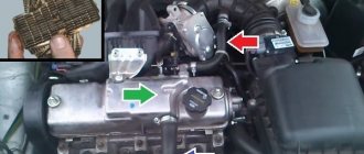
Removal: 1) The hardest thing is to remove the cylinder head cover, but the remaining parts that relate to the ventilation system (And these are mainly hoses), removing is as easy as shelling pears, in general, let's start, first you will need to disconnect the wires from each other, namely the upper connectors (see photo 1 ) and lower connectors (Indicated by a red arrow), once this is done, remove the connectors, to do this, squeeze the two latches on one connector with your fingers and remove it (see photo 2) and do the same with the other connector, just without removing it, they will interfere, and in general you won’t be able to remove the cylinder head cover without removing these connectors, because the wires simply won’t allow you to do this, both connectors were sitting on brackets, so unscrew the bolts securing them and remove both brackets from the cylinder head cover, in more detail how to do this , look at photos 3 and 4 below.
2) Now remove the exhaust manifold from the cylinder head cover, it is bolted on and by the way, when you remove it, replace all the O-rings, firstly they are not expensive and secondly, after replacement, you will be 100% sure that the collector will not let air through anywhere, since the rings will be new; you can read in more detail how to do this in the article entitled: “Replacing the receiver on a 16-valve car.”
3) Then start removing the hoses, they are held in place by clamps, the clamps are loosened using a screwdriver or wrenches, if it is not convenient to work with a screwdriver, all the clamps that you will need to loosen and all the hoses that you will need to remove, you can see in the photographs a little below:
Note! Rinse the removed hoses with gasoline or kerosene, then dry them in the sun and, if possible, also blow them with compressed air (for example, a compressor), before installation, make sure that the hoses are dry, if necessary, wipe them dry with a rag and by the way, Carefully clean all those places where the hoses are connected with a cloth and remove all dirt from them!
4) When everything is finished, remove the cover from the Cylinder Head, it is secured with fifteen bolts, these bolts are unscrewed with a socket wrench or a socket head and an “8” wrench, then the cover is separated from the cylinder head with a screwdriver and removed from the car, it is most convenient to separate it from the cylinder head in those places where there are special protrusions for this, one of such protrusions is indicated by a blue arrow.
5) After you have the cylinder head cover in your hands, using a wrench or a socket wrench, unscrew the six bolts that secure the separator to it (Several bolts are indicated in the large photo) and disconnect it from the cover (see small photo).
Note! This separator is an integral part of the crankcase ventilation system, it has such a part as an oil deflector, to pull it out, you will need to compress the side clamps using pliers (see photos 1,2), a rubber o-ring will be installed on the oil deflectors, picking it up with a screwdriver , you also need to remove it (see photo 3,4) and replace it with a new one, if such a ring is difficult to find in car shops, then you are allowed not to change it if it is in good condition, namely: It should not be too compressed, the rubber is not should become rough and lose its elasticity, and there should be no cracks or other types of damage on the ring!
Installation: Installation of all parts is carried out in the reverse order of removal, but before installation, wash everything thoroughly with gasoline or kerosene, this also applies to the cylinder head cover itself, there should be no dirt on it, and also remove old sealant (with a screwdriver or fine-grained sandpaper) the surface where the cylinder head cover is installed, after cleaning, degrease it and apply a new sealant, as it is shown in the small photo below:
Additional video: An interesting video that will give you a little additional information on the crankcase ventilation system is located just below:
Source
Drives oil through the breather: diesel and gasoline internal combustion engines
Engine diagnostics for oil leaks through the breather requires an integrated approach. There is no need to disassemble the power unit to check. It becomes clear that at the initial stage you should assess the condition of the breather, make sure it is working and clean the device if necessary. The oil level is also checked using the dipstick. If everything is fine with the level and there are no other additional signs of a problem, then it is optimal to replace the breather with a known good one.
After making sure that the breather is working properly and ventilation is at an acceptable level, you will need to make a series of measurements and assess the condition of the CPG. As already mentioned, the cause may be failed rings, that is, you will need to measure the compression in the engine.
Also, the color of the exhaust gases can additionally indicate the need to measure compression. To check, just start the engine and then evaluate the exhaust. If the engine smokes blue or gray smoke, then this may be a sign of engine oil getting into the cylinders due to worn piston rings. When checking compression, you need to take readings in each individual cylinder. In the normal state of the CPG, compression should be at 11 MPa and above (it is recommended to consult the technical literature in relation to a specific type of internal combustion engine). If a run-up is detected according to the readings in the cylinders, the differences should not exceed 1 MPa.
Failure to reduce compression will indicate that further checks will be related to the ventilation system. The method for testing this system will be considered using the example of the domestic VAZ 2110 model. Other cars may have some individual features, but the general principle will be similar.
- At the very beginning, you need to disconnect the tubes from the valve covers, breather and air duct pipe. Then the degree of contamination should be assessed. If the tubes are clogged or dirty, then they can be cleaned with carburetor cleaner or gasoline. Afterwards you will need to blow them with compressed air or dry them naturally.
- Next you need to get to the oil separator by unscrewing the fixing bolts and removing its cover. After this, the oil separator itself is removed. This device is made of special plates. It is necessary to disassemble the element and wash it. Washing can be done in gasoline and then dried.
- At the same time, it is recommended to inspect and flush the valve, and also check the stroke of the rod. This is possible after removing the device. Valve jamming can also be eliminated by washing. The entire list of actions described allows you to keep the crankcase ventilation system clean and maintain its functionality.
Options for creating forced crankcase gas cleaning
The truth is that not everything is as simple as it seems at first glance. There are two approaches by which forced crankcase ventilation can be performed. Exhaust gases can be removed from the crankcase, and perhaps the opposite effect is the flow of air from outside.
An example of how a forced crankcase ventilation system based on exhaust gas removal is constructed is given above. In this case, the exhaust gases that have broken through are under the influence of vacuum in the intake manifold and enter through the oil separator (1), valve (2) and through hoses, having been cleared of oil particles, they again enter the engine cylinders.
An option when the ventilation system is built on the influx of fresh air is shown in the figure below. In this case, outside air enters the engine crankcase, mixes with crankcase gases, and flows back into the engine cylinders through a special PCV valve. A ventilation system constructed in this way avoids the release of internal combustion engine products into the atmosphere. This is exactly the approach used by modern automakers when designing and manufacturing cars.
To maintain normal engine operation at idle, the PCV valve blocks the exit of gases from the crankcase when there is a deep vacuum in the pipeline.
An indispensable attribute of a modern internal combustion engine is crankcase ventilation, most often designed as a closed system. It allows you to increase the reliability of the engine and reduce the negative impact of vehicle exhaust on the atmosphere. » alt=»»>
Symptoms of a Stuck PCV
- Engine misfires at idle
- Lean air-fuel mixture
- Presence of engine oil in PCV valve or hose
- Increased oil consumption
- Hard engine start
- Rough, unstable engine operation at idle
Additionally, a stuck PCV valve can cause a check engine light due to increased air flow. And the diagnostic computer may mistakenly show this error due to the mass air flow sensor or oxygen sensor, making it difficult for you to identify the real source of the problem.