Mass air flow sensor table. VAZ DMRV engines. Last three digits
But to implement them, it is necessary that the sensors informing the controller do not deceive it - only under this condition do the processes in the cylinders proceed normally, the engine develops sufficient power without consuming excess fuel and without causing much harm to the environment.
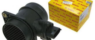
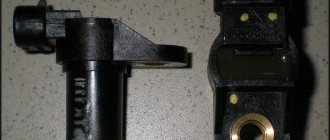
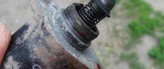
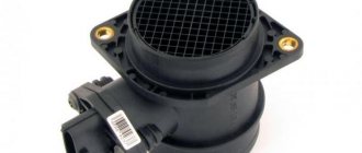
One of these sensors measures the amount of air entering the cylinders and generates a corresponding signal to the controller. This can be an absolute pressure sensor (MAP sensor) or a mass air flow sensor (MAF). We see the latter on many cars, including VAZ ones. The first was the frequency mass air flow sensor of the GM control system. It was also used in the domestic analogue “January” of the 4th series (photo 1). Cars of this configuration did not last long on the assembly line - the frequency sensor was replaced by an analog model HFM-5 from Bosch - its number is 0280218004 (photo 2). It is not interchangeable with GM - the connectors and mounting points are different. The German sensor is dismountable, consisting of two parts - a housing and a measuring element.
The latter is secured in the case with two screws with “secret” heads. True, nowadays you can buy the necessary tools in auto parts stores. The measuring element is a compact thing, but it is expensive - in Moscow from 1300 rubles. and higher. Having removed this part from a new car, in exchange, of course, they will put a dummy, and everything that follows is the “personal grief” of the car buyer. The market is full of such “mass air flow sensors without a housing”... It is unwise to buy a measuring element without a housing: it is very possible that it is faulty or the wrong model. Bosch only sells assembled sensors in traditional yellow cardboard packaging. Let us remind you that the store may not accept a return air flow sensor purchased from the “wrong system” if the motorist does not provide a certificate from the service, and it is often difficult to obtain one. An unnecessary expensive unit will remain as a keepsake.
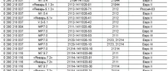
The third version of the mass air flow sensor is 037. (Here we are talking about the last three digits in the designation.) This is a further development of the 004th sensor from Bosch. Such a sensor is used today on most VAZ cars traveling on the roads, including Niva and Chevrolet Niva. Externally, 004 and 037 are almost indistinguishable - just look at the number (photo 3). Recently, additional markings have appeared on products: now there are numbers on both the body and the measuring element - they must match. The main difference is inside the mass air flow sensor. In photo 4 on the right is the 037th sensor. It has a different design of the measuring element, with a characteristic cutout (when purchasing, it makes sense to remove the plug and look inside).
But now a new control system has appeared - Bosch-M7.9.7, which has its own, 116th, mass air flow sensor. It is not interchangeable with the previous ones, although its body is the same. To avoid confusion, a green circle was initially applied to the body (photo 5). There are numbers on both the body and the measuring element (photo 6). The latter determines the purpose of this mass air flow sensor - the design has been changed again (photo 7). To prevent elements from being replaced on the way from the factory to the consumer, the kind German designers installed other secret screws. Eh, naive! The required tool is already sold on the Russian market. Carefully inspect the mass air flow sensor: when unscrewing the secret screws, their coating is usually damaged. If you notice, draw your own conclusions!
The table will help you simplify your choice when buying a mass air flow sensor.
Purpose of the mass air flow sensor
The mass air flow sensor, or flow meter, is an important component of the injection engine of the VAZ 21093 i. It is responsible for the formation of the air-fuel mixture in the required proportions, for the supply of the proper volume of air oxygen to the combustion chambers. Depending on the MAF readings, the electronic engine control unit (ECU) determines the amount of gasoline injected into the cylinder and the specific moment at which the igniting spark is supplied.
The ECU takes into account not only the readings of the air flow sensor. It also uses other meters available in the car: throttle opening angle, temperature of the fluid circulating in the engine, detonation (designed to correct the advance angle in the event of detonation), oxygen (provides feedback on monitoring the quality of combustion of the mixture in the combustion chambers), crankshaft position , vehicle speed and, finally, a phase sensor (monitors the valve timing of a sixteen-valve engine).
Sensor readings are transmitted to the controller. Regulation based on these data ensures maximum engine power, minimum fuel consumption and the standard content of carbon monoxide in the exhaust gases.
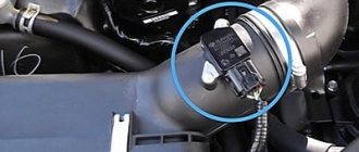
The mass air flow sensor on VAZ 2109 cars is installed in the air filter housing in the outlet line, in front of the air supply pipe to the engine.
Purpose and explanation of the abbreviation
Flow meters, also known as volume meters or mass air flow meters (not to be confused with mass air flow meters and mass air flow sensors), are installed in diesel or gasoline-powered vehicles. The location of this sensor is not difficult to find, since it controls the air supply, you should look for it in the corresponding system, namely, after the air filter, on the way to the throttle valve (DZ).
Installation location of mass air flow sensor on Gazelle 405
The device is connected to the engine control unit. In cases where the mass air flow sensor is in a faulty condition or is missing, a rough calculation can be made based on the position of the air flow sensor. But with this measurement method it is impossible to ensure high accuracy, which will immediately lead to excessive fuel consumption. This once again indicates the key role of the flow meter in calculating the fuel mass supplied through the injectors.
In addition to information from the mass air flow sensor, the control unit also processes data coming from the following devices: camshaft sensor (camshaft sensor), DD (knock meter), remote sensor, cooling system temperature sensor, acidity meter (lambda probe), etc.
Mass air flow sensor design
The most common automotive mass air flow sensors operate on the principle of the so-called “heated string”. The string is made of metal and can look different: for a GM device it is a wire with a diameter of about 70 microns, for a BOSH sensor it is a special mesh membrane. The string is placed in the flow of air entering the engine, which cools the metal.
An electric current is passed through the string, which in turn heats the string. Another similar string is placed outside the air flow and used as a temperature standard. The resistor bridge automatically supplies such electric current to the string in the air flow so that it remains heated to the reference temperature. The stronger the air flow, the greater the cooling of the string and the more electricity is required to maintain a stable temperature.
The string is made of platinum: the resistance of this metal strongly depends on temperature. This ensures high sensitivity of the device and accuracy in determining air flow speed. By measuring the voltage on the “heated string”, the device determines the speed of the incoming air. It is the speed of the flow, multiplied by the cross-sectional area of the channel, that determines the volume of air entering the engine per unit time.
In physics, there are two types of mass: gravitational (as in the law of universal gravitation) and inertial (as in Newton’s second law, connecting mass, force and acceleration). The injector sensor on the VAZ 2109 does not measure either gravitational or inertial mass at all. It determines not the mass, but the volumetric air flow. This is correct from the point of view of the theory of operation of the internal combustion engine, which is described in thermodynamic concepts. We are always talking about pressure, temperature, working volume of a gas, but not about its mass.
The electronic control unit linearizes the mass air flow sensor measurements and issues control commands to the injector taking into account the air temperature, its humidity and the current operating mode.
The second way is using a multimeter
Before performing these diagnostics, it should be noted that this will only work with a Bosch mass air flow sensor. Before performing the test, set the limit on your multimeter to 2 V, and then switch the device to constant voltage operation.
Turn on the ignition and connect the red wire to the yellow one on the block. Connect the black wire to the green one. At this moment the engine should not be running. Measure voltage
If the reading is between 1.01 and 1.02, then everything is fine. The multimeter shows voltage up to 1.03 - there is nothing to worry about, this is acceptable. The limit level is 1.05. If it is higher, then you can again look for the cause of the breakdown.
Diagnosis of device malfunctions
Determining a problem with the mass air flow sensor is not so easy. Many symptoms of failure of this sensor coincide with signs of failure of other components and assemblies of the car. Typical symptoms of problems with the mass air flow sensor are cases when:
- the engine noticeably loses power;
- there are failures when pressing the accelerator;
- fuel consumption increases significantly;
- Starting a warm engine becomes more difficult.
When the mass air flow sensor fails, the Check Engine light on the dashboard lights up. But it turns on not only when the mass air flow sensor fails. And it’s not at all easy to figure out what kind of breakdown the indicator is signaling in this case, so it’s better to turn to professionals for diagnostics.
Cases when the average car enthusiast can figure it out on his own are relatively rare. These include a situation when you suspect a failure of the mass air flow sensor, and your friend has the same “nine” as yours with a perfectly working engine. Borrow a known-good air flow sensor from a friend for one hour. Remove your sensor, install a good one, and go for a ride. If the problems disappear, go to the store for a flow meter: the problem is that the mass air flow sensor is broken.
Features, diagnostics and replacement of elements of injection systems on VAZ cars
Below we will look at the main controllers!
Hall
There are several options for how you can check the Hall sensor of a VAZ:
- Use a known working device for diagnostics and install it instead of the standard one. If after replacement the problems in engine operation cease, this indicates a malfunction of the regulator.
- Using a tester, diagnose the controller voltage at its terminals. During normal operation of the device, the voltage should be from 0.4 to 11 volts.
The replacement procedure is performed as follows (the process is described using the example of model 2107):
- First, the switchgear is dismantled and its cover is unscrewed.
- Then the slider is dismantled; to do this, you need to pull it up a little.
- Remove the cover and unscrew the bolt that secures the plug.
- You will also need to unscrew the bolts that secure the controller plate. After this, the screws that secure the vacuum corrector are unscrewed.
- Next, the retaining ring is dismantled and the rod is removed along with the corrector itself.
- To disconnect the wires, you will need to move the clamps apart.
- The support plate is pulled out, after which several bolts are unscrewed and the manufacturer dismantles the controller. A new controller is being installed, assembly is carried out in the reverse order (the author of the video is Andrey Gryaznov).
Speeds
The following symptoms may indicate a failure of this regulator:
- at idle, the speed of the power unit floats, if the driver does not press on the gas, this can lead to an arbitrary shutdown of the engine;
- the speedometer needle readings float, the device may not work as a whole;
- fuel consumption has increased;
- the power of the power unit has decreased.
The controller itself is located on the gearbox. To replace it, you only need to jack up the wheel, disconnect the power wires and remove the regulator.
Fuel level
The VAZ or FLS fuel level sensor is used to indicate the remaining volume of gasoline in the fuel tank. Moreover, the fuel level sensor itself is installed in the same housing with the fuel pump. If it malfunctions, the readings on the dashboard may be inaccurate.
The replacement is done like this (using the example of model 2110):
- The battery is disconnected and the rear seat of the car is removed. Using a Phillips screwdriver, unscrew the bolts that secure the fuel pump hatch and remove the cover.
- After this, all wires leading to it are disconnected from the connector. It is also necessary to disconnect all the pipes that are supplied to the fuel pump.
- Then the nuts securing the clamping ring are unscrewed. If the nuts are rusty, treat them with WD-40 before unscrewing.
- Having done this, unscrew the bolts that directly secure the fuel level sensor itself. The guides are pulled out from the pump casing, and the fasteners need to be bent with a screwdriver.
- At the final stage, the cover is dismantled, after which you will be able to gain access to the FLS. The controller is replaced, the pump and other elements are assembled in the reverse order of removal.
Idle move
If the idle speed sensor on a VAZ fails, this is fraught with the following problems:
- floating speed, in particular, when additional voltage consumers are turned on - optics, heater, audio system, etc.;
- the engine will start to stall;
- when the central gear is activated, the engine may stall;
- in some cases, failure of the IAC can lead to body vibrations;
- the appearance of a Check indicator on the dashboard, but it does not light up in all cases.
Preventive repair of mass air flow sensor
A broken flow meter cannot be repaired. The exception is cases of contamination of the sensor, which impairs its performance. In these cases, preventive repair of the air flow sensor can be carried out. The VAZ 2109 has a special self-cleaning mechanism for the platinum string of the flow meter: it is periodically heated to a temperature above 1000 degrees. Timely replacement of the air filter also helps keep the sensor element clean.
It is known that the mechanism cannot be damaged by cleaning.
| Main stages | Your actions |
| Before dismantling the mass air flow sensor, do not forget to de-energize the system. | Disconnect the six-pin wiring harness from the sensor. Loosen the clamp and disconnect the air filter pipe. Using a 10mm wrench, unscrew the bolts securing the flow meter to the air filter housing. |
| Carefully remove the sensor. | From a distance of 12–15 centimeters, generously spray a special carburetor cleaning spray from an aerosol can. Be careful to avoid getting the spray on your skin - it is very caustic. |
| Let the spray flow and dry. | If necessary, repeat the procedure two or three more times. |
| Mount the flow meter in reverse order. | Take a ride. If the problem persists, remove the electrical connector from the sensor. |
The controller will go into standby mode, increase idle speed and increase fuel consumption, but will ensure uninterrupted engine operation. Next, let the professionals deal with your problem: take a course at a proven car service center.
Source
Interchangeability
This issue is quite relevant, especially taking into account the cost of original products from the imported automobile industry. But it’s not so simple here; let’s give an example. In the first production models of the Gorky Automobile Plant, the injection Volgas were equipped with a BOSCH air flow sensor. Somewhat later, imported sensors and controllers replaced domestic products.
A – imported filament air flow sensor manufactured by Bosh (pbt-gf30) and its domestic analogues B – JSCB “Impuls” and C – APZ
Structurally, these products were practically no different with the exception of several design features, namely:
- The diameter of the wire used in a wirewound thermistor. Bosch products have a diameter of 0.07 mm, and domestic products have a diameter of 0.10 mm.
- The method of fastening the wire differs in the type of welding. For imported sensors this is resistance welding, for domestic products it is laser welding.
- Shape of a thread thermistor. Bosh has a U-shaped geometry, APZ produces devices with a V-shaped thread, and products from JSC Impulse are distinguished by the square shape of the thread suspension.
All the sensors given as an example were interchangeable until the Gorky Automobile Plant switched to film analogues. The reasons for the transition were described above.
Film air flow sensor Siemens for GAZ 31105
It makes no sense to give a domestic analogue to the sensor shown in the figure, since outwardly it is practically no different.
It should be noted that when switching from filament devices to film devices, most likely, it will be necessary to change the entire system, namely: the sensor itself, the connecting wire from it to the ECU, and, in fact, the controller itself. In some cases, the control can be adapted (reflashed) to work with another sensor. This problem is due to the fact that most filament flowmeters send analog signals, while film flowmeters send digital signals.
VAZ air flow sensor pinout. Checking and repairing the air flow sensor
Based on the signal from the mass air flow sensor (MAF), the cyclic filling of the cylinder is calculated, which is ultimately converted into the duration of the injector opening pulse. If it does not work correctly, the car consumes more gasoline than necessary. Such a sensor is installed on the second path, immediately behind the air filter and connected to the electrical system, which is controlled by a six-pin block of wires.
There are quite a few different types of mass air flow sensors: mechanical, ultrasonic, hot-wire and some others.
In this case, we will consider the design of the HFM-5 hot-wire sensor from Bosch, which is most often installed on VAZ cars. The sensor's sensitive element is a thin film on which several temperature sensors and a heating resistor are located. In the middle of the film there is a heating area, the degree of heating of which is controlled using a temperature sensor.
On the surface of the film, on the side of the air flow and on the opposite side, two more thermal sensors are located symmetrically, which record the same temperature in the absence of air flow. In the presence of air flow, the first sensor is cooled, and the temperature of the second remains unchanged, due to the heating of the air flow in the heater zone. The differential signal of both sensors is proportional to the mass of passing air.
- 1 - dielectric diaphragm
- H - heating resistor
- SH - Temperature sensor naked. resistor
- SL - Air temperature sensor
- S1 and S2 - temp sensors before and after the heater.
- QLM - air flow mass
- t—temperature
The sensor's electronic circuit converts this signal into a constant voltage proportional to the air mass. This design is called Hot Film (HFM), its advantages include high measurement accuracy and the ability to record reverse air flow, but its disadvantages include low reliability in conditions of contamination and moisture.
To measure the amount of air that enters the engine means to determine the engine load. When the driver presses the gas pedal, the throttle valve opens and the amount of intake air increases. At the same time, we say that the load has increased. When you release the pedal, the load drops. It's quite simple. However, this is only at first glance. If we take into account the fact that in real driving conditions the engine often changes operating modes and the incoming air in the intake system participates in several gas-dynamic processes, then the problem of measuring the air in the system is not so simple.
In older systems (ECU January-4 and GM-ISFI-2S), other hot-wire mass flow sensors were used, the sensitive elements of which were made in the form of threads. Such sensors are called Hot Wire MAF Sensor. The output signal of these sensors was frequency, that is, depending on the air flow, it was not the voltage that changed, but the frequency of the output pulses. The sensors were less accurate and did not allow registering reverse flow, but these shortcomings were offset by very high reliability.
Types of mass air flow sensors, their design features and operating principle
Three types of VU meters are most widespread:
- Wire or thread.
- Film.
- Volumetric.
In the first two, the operating principle is based on obtaining information about the mass of the air flow by measuring its temperature. The latter may involve two accounting options:
- By changing the position of the slider, driven by a special blade, which is affected by the air flow passing through the device. Considering the presence of rubbing mechanisms, the level of reliability of such structures is quite low. This was the main reason for the refusal of car manufacturers from sensors of this type. For reference, here is a simplified example of the design of a volumetric flow meter.
Volumetric air flow sensor device - By counting Karman vortices. They are formed if a laminar air flow washes over an obstacle whose edges are quite sharp. The frequency of the vortices breaking off from them is directly related to the speed of air flow passing through the device.
Vortex sensor design (widely used by Mitsubishi Motors)
Designations:
- A – pressure measurement sensor to record the passage of the vortex. That is, the frequency of pressure and vortex formation will be the same, which makes it possible to measure the flow of the air mixture. At the output, using an ADC, the analog signal is converted to digital and transmitted to the ECU.
- B - special tubes that form an air flow similar in properties to laminar.
- C – bypass air ducts.
- D – column with sharp edges on which Karman vortices are formed.
- E – holes used to measure pressure.
- F – direction of air flow.
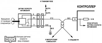
VAZ 2110 air sensor pinout diagram
- Yellow (closest to the windshield) - mass air flow sensor signal input;
- Gray-white—sensor supply voltage output;
- Green — sensor grounding output;
- Pink-black - to the main relay.
The wire colors may change, but the pin locations remain the same.
Let’s also add that the mass air flow sensor with endings 004, 037, 116 (for Bosch) and 00, 10, 20 (for Pekar) are different in calibration. You can only change it by flashing it.
What does a faulty air flow sensor cause?
Operating an engine with an inoperative/faulty flow meter causes detonation of the fuel mixture in the combustion chamber. This affects the operation of the crank mechanism (crank mechanism) and destroys the piston surface, which can cause a “wedge” in the engine.
What indications should a working mass air flow sensor give?
The voltage of the analog-to-digital converter (ADC) of the flow meter when the engine is not running should be 0.996 V. Indicators of 1.016 and 1.025 V are acceptable, but if they reach more than 1.035 volts, it means that the sensing element of the mass air flow sensor is clogged.
To accurately determine the degree of deviation of the operating flow meter values from normal values, it is necessary to evaluate the engine operation at different speeds.
For example, for an injection 1.5-liter VAZ 2111 engine, if it is in good condition, at idle (860–920 rpm) the correct readings are 9.5–10 kg/hour, and at 2 thousand rpm - 19 –21 kg/hour. If the flow meter at 2 thousand rpm shows about 17–18 kg, then the car will drive stably. If the values are from 22 to 24 kg/hour, then the vehicle will move steadily, but the fuel consumption per 100 km will be approximately 10–11 liters. In addition, the car will have difficulty starting in cold weather due to fuel overflow when the engine warms up.
Connecting the MAF air sensor VAZ 2112
If the mass air flow sensor is operational, then when the engine is running at 900 rpm, the volume of air used will be at least 10 kg per hour. When the speed increases to 2 thousand, this figure will increase to approximately 20 kg. If the volume of air at such speeds drops, the dynamics of the vehicle will also decrease, and accordingly, this will lead to a decrease in gasoline consumption.
If these indicators increase, this will also contribute to an increase in fuel volume. Deviations of the parameter by 2-3 kg should not be allowed, since in this case the operation of the power unit may be incorrect.
System depressurization
If depressurization occurs in the intake tract system, then instability in engine operation occurs. Air leaks occur in the following parts of the car:
- In sealed areas of the nozzle;
- On exhaust systems for gasoline vapors;
- On the walls of the throttle frame;
- On idle jets;
- On the vacuum brake booster pipes;
- On the cleaning pipes.
Due to improper air removal, improper mixing of fuel masses occurs. Emergency symptoms are detected during the operation of the intake tract. The air leaving the system does not pass through the filtration system. It contains many harmful particles of dirt, metal, and plastic, which enter the engine and threaten to lead to poor performance of the latter.
Connection diagram for air flow sensor 2114
A common cause of incorrect operation of the mass air flow sensor is the failure of electronic components, which increases the sensor’s response time to changes in air flow. A working sensor monitors changes at a speed of 0.5 ms, and if it breaks down, the response time increases by 20-30 times. The defect is detected only by recording the operation graph with an oscilloscope. Such a sensor cannot be repaired; it must be replaced with a new one.
Functionality check
Before diagnosing the mass air flow sensor, you need to know the symptoms that allow you to determine the degree of performance of the MAF (abbreviation for the English name of the device) sensor in the car. We list the main symptoms of a malfunction:
- The consumption of the fuel mixture has increased significantly, while at the same time acceleration has slowed down.
- The internal combustion engine idles with jerks. In this case, a decrease or increase in speed may be observed in idle mode.
- The engine does not start. Actually, this reason in itself does not mean that the flow meter in the car is faulty; there may be other reasons.
- A message appears about a problem with the engine (Cheeck Engine)
Example of the "Cheeck Engine" message displayed (marked in green)
These signs indicate a possible malfunction of the mass air flow sensor; in order to accurately determine the cause of the failure, diagnostics must be performed. It's easy to do it yourself. Connecting a diagnostic adapter to the ECU (if this option is possible) will help to significantly simplify the task, and then determine the serviceability or malfunction of the sensor using the error code. For example, error p0100 indicates a fault in the flow meter circuit.
Finding an error using a diagnostic adapter
But if you need to carry out diagnostics on domestic cars manufactured 10 years ago or more, then checking the mass air flow sensor can be carried out in one of the following ways:
- Testing while moving.
- Diagnostics using a multimeter or tester.
- External inspection of the sensor.
- Installation of a similar, known-good device.
Let's consider each of the listed methods.
Testing while driving
The easiest way to check is by analyzing the behavior of the internal combustion engine with the MAF sensor disabled. The algorithm of actions is as follows:
- You need to open the hood, turn off the flow meter, close the hood.
- We start the car, and the internal combustion engine goes into emergency mode. Accordingly, a message indicating a problem with the engine will appear on the dashboard (see Fig. 10). The amount of fuel mixture supplied will depend on the position of the remote control.
- Check the dynamics of the car and compare it with what it was before the sensor was turned off. If the car has become more dynamic and power has also increased, then this most likely indicates that the mass air flow sensor is faulty.
Note that you can continue driving with the device turned off, but this is highly not recommended. Firstly, the consumption of the fuel mixture increases, and secondly, the lack of control over the oxygen regulator leads to increased pollution.
Diagnostics using a multimeter or tester
Signs of a malfunction of the mass air flow sensor can be identified by connecting the black probe to ground, and the red probe to the sensor signal input (the pinout can be found in the device data sheet, the main parameters are also indicated there).
An example of measuring the voltage on the mass air flow sensor in a VAZ 2114 car with a multimeter
Next, we set the measurement limits to 2.0 V, turn on the ignition and take measurements. If the device does not display anything, you need to check that the probes are connected correctly to ground and the flow meter signal. Based on the readings of the device, you can judge the general condition of the device:
- A voltage of 0.99-1.01 V indicates that the sensor is new and working properly.
- 1.01-1.02 V – used device, but its condition is good.
- 1.02-1.03 V - indicates that the device is still operational.
- 1.03 -1.04 the condition is approaching critical, that is, in the near future it is necessary to replace the mass air flow sensor with a new sensor.
- 1.04-1.05 – the device’s resources are almost exhausted.
- Over 1.05 - a new mass air flow sensor is definitely needed.
That is, you can correctly judge the state of the sensor by the voltage; a low signal level indicates an operational state.
External inspection of the sensor
This diagnostic method is no less effective than the previous ones. All that is necessary is to remove the sensor and assess its condition.
Inspect the sensor for damage and fluid
Characteristic signs of a malfunction are mechanical damage and liquid in the device. The latter indicates that the oil supply system to the engine is not adjusted. If the sensor is very dirty, the air filter should be replaced or cleaned.
Installing a similar, known-good device
This method almost always gives a clear answer to the question of the sensor’s performance. This method is quite difficult to implement in practice without purchasing a new device.
Checking the air sensor yourself
When a malfunction of the mass air flow sensor occurs, the air-fuel mixture becomes over-rich or lean, which immediately affects the operation of the engine and may ultimately result in engine failure.
Symptoms of a malfunctioning mass air flow sensor:
- Check Engine error appears;
- Increased fuel consumption;
- Doesn't start well when hot;
- The car began to accelerate slowly;
- Engine power lost.
The first method is to disable the sensor
This verification method is the simplest. Every car owner can do it. The first step is to turn off the sensor. To do this, you just need to unplug the connector. Then you should start the engine. As a result, the ECU controller will go into emergency mode. And the supply of the fuel mixture will be regulated only using the throttle valve. Idle speed will be around 1500 rpm. After this, you need to check in by car. If the car has improved its dynamic acceleration characteristics, then it makes sense to look for signs of a malfunction of the mass air flow sensor.
Replacing the sensor - instructions
Using a screwdriver, unscrew the clamp of the air intake corrugation at the sensor outlet, pull it off and carefully inspect the internal surfaces of the sensor itself and the corrugation. These surfaces must be dry and clean; traces of condensation and oil are unacceptable. If the air filter is changed rarely, then dirt getting on the sensitive element of the sensor is the most common cause of its breakdown in VAZ cars.
There may be oil in the mass air flow sensor as a result of an increased oil level in the engine crankcase, or the oil sump of the crankcase ventilation system is clogged.
Next, unscrew the 2 screws of the sensor with a 10mm wrench and remove it from the air filter housing. There should be a rubber sealing ring on its front part (at the entrance edge). It prevents unfiltered air from being sucked into the intake tract through the sensor.
If the ring is out of place and stuck somewhere in the air filter housing, then there will be a thin layer of dust on the inlet mesh of the sensor itself. This is the second reason that destroys the mass air flow sensor ahead of time.
Correct assembly should take place in the following sequence: put a sealing rubber band on the sensor, check the sealing skirt, then insert everything together into the filter housing.
This concludes the visual check of the mass air flow sensor at home. You can check its operation 100% only with the help of special equipment in a car service center. For example, using a technique for assessing the oscillogram when the throttle is sharply opened to the cutoff mode (a motor tester is needed), or assessing the oscillogram when the ignition is turned on.
Resuscitation of a damaged air flow sensor is successful in no more than 5% of cases. In extreme cases, you can rinse with ethereal liquid to clean matrices and optics. It will evaporate without a trace. After making sure that there is no more dust or debris in the device, you can dry it thoroughly and put it back in place. Sometimes after such a simple procedure the device will work.
On most foreign cars, a mass air flow sensor was installed until 2000; subsequent generations of models began to be equipped with a pressure controller. Replacing a non-working sensor is simple and can be done on your own without any problems, you just need to buy a mass air flow sensor that matches the ECU firmware version. Its price is around 3,000 rubles, depending on the manufacturer.
Source
What is the difference between sensors 037 and 116?
How can the regulators of these models differ from each other and is it possible to install 116 instead of 037? There are differences between these controllers, and the point is not in the MAF pinout. After all, if these models were the same, what would be the point of giving them different names?
So, how do the controllers differ from each other and is it possible to install model 116 instead of 037:
- The first difference that can be guessed based on the technical characteristics is that the 037 model can produce data with an error during operation. Of course, an error of 2.5% is not critical, but it does exist.
- Device 037 is intended for installation in VAZ 2111, 2112, 2123, 21214 cars, which are equipped with controllers M 1.5.4, January 5.1-5.1.3, etc.
- As for model 116, its use is relevant on Ladas 21114, 21124, 21214. Installation of this device is allowed on Kalina and Priora. Installation of the device is allowed on cars equipped with M 7.9.7 and January 7.2 controllers.
If you encounter a problem with the device not working, then when replacing it you need to install the same model that has already been installed. But it is worth considering that 037 is not a common option like 116, so it is more difficult to find. The latter, in turn, is more common, and its cost is lower.
Replacement is allowed, but experts do not recommend this. This is because these devices differ in their calibration, so in case of replacement, you will have to change the parameters of the control unit. And you can only get into the “brains” of a car if you understand what needs to be done and have minimal experience.
Loading …