Every modern vehicle uses a speed monitoring system so that the motorist can be aware of the driving speed. The elements that are part of this system must be working, since the motorist must know the speed of movement. What is the VAZ 2110 speed sensor used for, what malfunctions are typical for it, how to replace the device? We will talk about this below.
Repair and replacement
We carry out dismantling according to the following scheme:
- We de-energize the car by removing the “-” connector from the battery;
- We disconnect the wire connector from the sensor and remember what their pinout is;
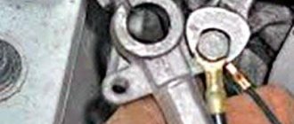
- We unscrew the sensor itself by hand. If this doesn’t work, use key 21 or 22 (there may be design differences);
- At the same time, we check how the drive feels. After removing the sensor, you need to unscrew the nut with which the drive is attached to the gearbox. You need to remove it very carefully, since if you drop the rod into the gearbox, you will have to disassemble it too. The new drive has a rubber ring, which is lubricated with transmission oil before installation.
We install new devices in the reverse order. Again, the pinout of the wires is of particular importance.
Inside the block we look at how the pinout is marked. And using a multimeter with the ignition on, we determine which connector goes to which wire.
If the multimeter shows “minus”, and you connected this wire to the plus connector, then you urgently need to change the polarity. In this regard, it is better to take the block that we recommend.
But if there isn’t one, you can use the regular one. In this case, the pinout is as follows: 1 – “+”, 2 – signal output, 3 – “-”.
The drive is checked, as well as the operation in general while the car is moving, or with the front wheels hanging.
Design
The sensor on the VAZ 2110 comes in two types, and it depends on which gearbox is installed on the car. If the gearbox is from a VAZ 2108, then the sensor is installed on a threaded connection, and if the gearbox is from a VAZ 2110-12, then the sensor is installed through an o-ring and pressed with a bolt to the body.
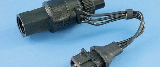
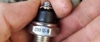
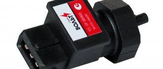
The design of both sensors is different; one of them is electromagnetic, and the second, older one, converts mechanical movements into electrical signals.
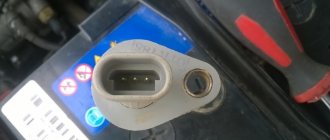
On the left is the sensor of the new type, and on the right is the old one.
Symptoms of problems, checking the speed sensor
If the odometer is not working, and the speedometer is “jerky”, transmitting false speed or mileage readings, we can conclude that the speed sensor is faulty.
There is also the possibility that these are signs of electrical circuit problems, especially if the car has ever been tampered with. There may be a break or oxidation of the connectors, rubbing of the wiring insulation, which causes a short circuit.
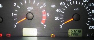
Also, a sign of breakdowns are cases in which the car may stall at idle. Perhaps the most obvious symptom of a speed sensor failure will be incorrect speedometer readings and the “ChekEngine” light on the panel.
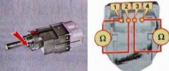
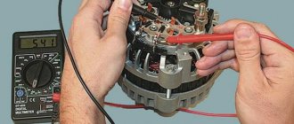
These devices have three contacts: ground, pulse signal, voltage. First, you should check the functionality of the grounding and the presence of voltage.
To check the speed sensor you need:
- Remove this sensor;
- Using a multimeter, calculate the contact that produces a pulse signal. “We install a plus to it, and attach the minus to the body of the car.
- Carefully rotate its rod. At the same time, you should monitor the output signal. If the sensor rod starts to rotate faster, the voltage will be higher.
Replacement or repair methods
Disassembly and removal is carried out as follows:
1. Remove the negative connector from the battery, having previously de-energized the car;
2. The wire connector is separated from the sensor;
3. The sensor is sometimes unscrewed by hand, but if it is difficult, you can unscrew it using twenty-one-twenty-two keys (sensors may vary in design);
4. We diagnose the drive condition
When removing, be careful, because when the drive rod breaks, there is a danger of dropping it into the gearbox; it can only be retrieved by disassembling the gearbox
The old sensor cannot be repaired. The new sensor should be installed using the reverse sequence shown. Don't forget to put the connector block on the sensor. Good luck on the roads and of course no breakdowns.
Why the speedometer does not work on a VAZ-2112: the main reasons for a 16 valve engine
When the speedometer does not work on a VAZ-2112 hatchback, the reasons may be different. Usually they try to repair the tidy, but the speed sensor turns out to be faulty. The ECU detects a malfunction of this sensor with difficulty, and the CHECK lamp does not turn on. The fact that the speed sensor is broken has to be identified by the following signs: idle speed always remains low, and the engine stalls when changing gears. These nuances will be discussed in more detail below, but we will only talk about 16-valve valves.
If all devices do not work, then one fuse is at fault. The video shows which one.
Electrical diagram
The sensor itself is powered by a voltage of 12 Volts (pink-black cord), and another pin is connected to ground. The gray wire is the sensor output. It is connected to the voltage source through a resistor (see figure).
Typical connection diagram for DS on a VAZ-2112
The diagram shows that the output is connected to the ECU terminal. Terminal number:
- 9 – block January 5.1, also BOSCH M1.5.4N (engine 21120, 1.5 l);
- 59 – BOSCH M7.9.7 module (ICE 21124, 1.6 l).
Another gray cord goes to the “red” block on the dashboard, where it connects to terminal 9.
As you can see, everything is elementary.
Instrument panel test on video (speedometer self-diagnosis)
There are some things we don't specifically consider.
Power to the circuit shown in the previous chapter comes from main relay 6. It is also called the “ignition relay”. There is also fuse 1 in the circuit.
Additional relay and fuse box
When the ignition circuit is broken, both the speedometer and the ECU module do not work on the VAZ-2112, and the engine does not start at all. So advice about checking the relay would seem stupid.
Advice for those who have an oscilloscope
If you still decide to dismantle the sensor, connect a 1 kOhm resistor to its output (to the middle terminal). The resistor tap is connected to the “plus” of the power supply. By turning the shaft by hand, pulses can be observed at terminal 2. There are six pulses per revolution.
Mechanics
The following diagram shows exactly how the speed sensor is designed.
Speed sensor for VAZ-2112
- 2110-3843010-13 – sensor;
- 2110-3843010-18 – sensor;
- 2108-3802820-10 – speedometer drive;
- 2101-3802718 – gasket;
- 2108-3802822 – drive housing;
- 2108-3802830 – sealing ring;
- 2108-3802834-20 – driven gear;
- 2108-3802833-20 – drive gear;
- 2101-3802717 – washer;
- 15896211 – M6 nut;
- 12601271 – wavy washer;
- 11500121 – pin M6x14.
Elements 1 and 2 are interchangeable.
Dismantling
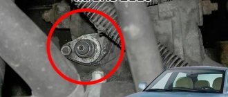
To remove the sensor from the car, you need to disconnect its connector. The sensor housing is fixed near the CV joint - the desired point is shown by an arrow.
First step in dismantling
When the connector is disconnected, take a flat key “22” and unscrew the plastic nut. Then you can change the sensor or repair it.
What you need here is a flat key
To replace the sensor drive, use a “10” key to unscrew the M6 nut and remove it together with the washer. The drive housing is rocked from side to side - you need a 14mm spanner.
Dashboard connectors and speedometer contacts
The dashboard, as well as the speedometer on the VAZ-2112, may not work when they are disconnected from ground or power. Be aware that the speedometer receives power separately from the instrument panel. This also applies to the “mass”. Wiring:
- X2-2: +12V for speedometer;
- X2-3: speedometer “ground”;
- X1-9, X1-10: power supply for tidy;
- X1-1: “mass” of the tidy.
Connector X2 is painted red, X1 – white. Terminals 8 and 9 in connector X2 are the speedometer output and input. The output is connected to the on-board computer.
Both terminals (X1-9 and X2-2) are connected to one wire - orange. This line is protected by a fuse installed in the main mounting block (F19).
How to remove the tidy
First, disconnect the negative terminal of the battery. Then use a screwdriver to unscrew the 4 screws (photos 1 and 2) to remove the frame with glass.
Removing the dashboard
In the second step, unscrew the two screws holding the dashboard in place (photo 3). Next, compress the petal brackets to remove the tidy completely.
- If you connect the battery and turn on the ignition, the orange cord (connectors X1 and X2) should receive voltage “+12”;
- The presence of “ground” at terminal X2-2 is also a very important indicator;
- The gray cord (terminal X2-9) is usually called “+12”, and in rare cases - “ground”. When moving, pulses should appear at this terminal.
Sometimes they do this: they make a tap from terminal 9, and, without engaging the gear, move (push) the car. The engine remains switched off. Pulses will appear on the tap, detectable even with a voltmeter. The voltmeter itself must be a pointer type.
It will not be possible to fix a faulty speedometer - it will be easier to replace it. But first you need to find out exactly what the problem was.
Preparing for replacement
In order for the procedure for replacing the controller on the tenth VAZ model to proceed correctly and to obtain the expected result, namely the normal functioning of the speedometer, you should be properly prepared for this process.
Firstly, on a VAZ 2110, replacing the DS means purchasing a new controller
When purchasing a new regulator, you need to pay attention to the fact that each connector located in the block design has certain symbols. It should contain the symbols “-”, “A” and “+”, not numbers
In principle, in this case there is not much difference between these options; when connecting the connector you will have fewer problems with pinout. If you have never encountered a process like this, this pinout will allow you to complete it correctly.
Controller connector pinout
One more, no less important nuance. You need to buy a device that is equipped with a metal rod. This rod will last at least six months, which cannot be said about regulators with plastic rods. In addition, when purchasing, you must check whether the rod rotates or not. It should not rotate, there should be no play on this element, and it should also be equipped with a washer.
Pinout DS 2109, 2110, 2112, 2114, 2115
If you understand how to connect the speed sensor, then there is the following pinout that you should follow. At the same time, it is important to understand the essence of the operation of the DS to study the circuit diagram of the sensor, which is attached to this article.
The factory speed sensor of VAZ cars is manufactured with some differences in connections to the block connector. The square-shaped connector is used in Bosh electronics systems. The circle-shaped connector is used in electronic systems such as January 4 and GM.
When connecting a sensor, you should choose devices with contact group digitization such as “-”, “A”, “+” (internal designation on the block contacts) instead of digital designations such as “1”, “2”, “3”. In addition, preference should be given to devices with a metal-type rod, since plastic rods are very short-lived.
Do I need to change it?
Not only the speedometer and odometer readings, but also the quality of the fuel mixture supplied to the cylinders, the idle speed of the vehicle, engine stability and fuel consumption depend on the information received by the ECU from the sensor.
A failed DS will “confuse” the electronic unit, which simply will not understand whether the car is moving or standing still. As a result, the speed will begin to fluctuate, the engine will stall at idle, and fuel consumption will increase.
Checking a mechanically driven speed sensor is not difficult. On the removed sensor, we find the pin and turn it with pliers, having attached the connector to it in advance. If the speed sensor is working, the arrow on the instrument cluster will jump, if there is no reaction, then there is a problem with the drive or electrical wiring.
Checking the wiring to the instrument cluster is also not difficult, take a paperclip (you can use any other metal object) and insert it into the middle pin on the connector, then touch it to the engine housing, the arrow on the combination should twitch, otherwise you need to look for the cause in a wiring fault or sensor connector (oxidation, breakage, etc.).
Video.
Schematic electrical diagrams, connecting devices and pinouts of connectors
The speed sensor is an element of the vehicle's electronic control system. It depends on its readings how much fuel will be supplied, how much air will bypass the throttle valve when idling, and what the speedometer readings will be.
The speed sensor of a VAZ car is based on the use of the Hall effect, that is, a stream of pulses is transmitted from the device to the car's ECU, the frequency of which is proportional to the speed of the car. Auto electronics, analyzing incoming data, selects the required idle speed and sends a signal to a device that regulates the engine idle speed, which optimizes the composition of the air-droplet mixture entering the combustion chamber, bypassing the throttle valve.
During a distance of one kilometer, the speed sensor transmits over 6000 pulses to the ECU. Based on the parameters of the time analysis of inter-pulse signals, the on-board computer transmits data to the dashboard, thereby determining the speedometer readings.
As in many other cars, the VAZ speed sensor is located in the upper part of the gearbox housing, not far from the engine oil level dipstick. You can get to it from two sides: from above, by opening the hood and disconnecting the adsorber, and from below, using the inspection hole for convenience.
Vehicle traffic control
This function is performed by the speed sensor, which takes part in the formation of the fuel mixture by the controller. It replaced the mechanical cable drive previously installed on carburetor VAZ 2112 models. The operating diagram of the element is as follows:
- The speed sensor is driven from a shaft located inside the gearbox.
- From the controller side, the device receives a reference voltage of 12 V.
- In response, the sensor produces a signal in the form of a pulse of a certain frequency. The frequency varies depending on the speed of the car.
- Based on these pulses, the controller controls the speed indicator and odometer on the dashboard, and also creates a rich or lean fuel mixture for the engine.
A malfunction of the speed meter is indicated by such signs as failure of the speedometer, unstable operation of the power unit and loss of idle speed when coasting. An indirect sign may also be the short-term display of the “Check Engine” sign on the instrument panel.
If you pay closer attention, increased gasoline consumption will become noticeable. If the sensor fails, you can continue driving, but you should replace it as soon as possible
The product cannot be repaired.
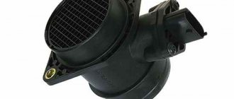
The device itself is a plastic box with a drive, from which wires come out in a bundle with a connection block. The block can be round or rectangular depending on the manufacturer of the product. The block from the Bosch brand is rectangular, from General Motors it is round.
A few words about how to check the speed sensor. The ideal option is to connect a laptop with the installed program for the VAZ 2110-2112 to the controller via the appropriate connector. But at home, the average motorist may only have a multimeter, and with its help he will have to test the operation of the element.
To do this, one front wheel of the car is suspended with a jack, and the wires leading to the controller are disconnected from the sensor. Instead, you should connect a multimeter and, by manually rotating the wheel, make sure that the readings change along with the rotation speed. If there are no changes, then it is better to change the product, otherwise, with such driving, more serious repairs will occur with the replacement of engine parts.
Principle of operation
The VAZ-2110 tachometer works according to the standard principle. It is part of an electrical circuit with the following elements:
- The device itself is located on the dashboard of the car and is completely electronic.
- The ignition module operates on the principle of an inductor. Necessary for converting direct current into pulsed current.
- Crankshaft position sensor or DPKV. It also converts electrical voltage into pulsed voltage.
- On-board computer or ECU. It is a receiver of pulse signals. Based on the frequency of incoming pulses, it makes calculations for the injection system, and also converts them into electrical voltage, adjusting the operation of the tachometer.
The whole circuit works as follows:
- After the power unit has started working, the crankshaft position sensor begins transmitting signals to the computer. Magnetic type crankshaft position sensor. Reacts to the absence of one tooth of the engine drive gear. As soon as an empty space passes near the sensor, it opens, thereby creating a pulse. For one revolution of the shaft, 1 pulse is created.
- The ignition module on the 8-valve version 2110 operates on the principle of generating pulse signals without rotation; it is stationary. The pulses are generated by 2 inductive coils. For one revolution of the power unit, 2 pulses are generated from the module. Due to pulses from the DPKV, the on-board computer transmits the discharge current to the ignition module.
- The pulse current transmitted from the DPKV to the ECU is converted into a constant voltage, which is transmitted to the tachometer receiver unit. The strength of the incoming current determines the strength of the magnetic field formed by the device’s coil, and therefore the angle of deflection of the tachometer needle.
The whole system is simple, consisting of a small number of elements. But any problem causes interruptions in the operation of the engine and the tachometer itself.
Next, a description will be given of the main symptoms that precede the tachometer failure.
When is diagnostics needed?
Due to the limited number of pulses and for many other reasons (motor oil, dirt has gotten on the sensor, contacts or wires located near the speed sensor have oxidized, there is mechanical damage to the part, etc.) in the “tens” it is often possible to observe flaws in the operation speedometer or its complete inoperability. At the same time, most often, problems arise when coasting at idle and the “CHECK” system lamp turns on (error code “24”). Be that as it may, any of the mentioned signs requires the car owner to mandatory diagnose the speed sensor, because the causes of malfunctions may lie in it, or they may lie in a completely different place.
How much does it cost to replace a speed sensor on a VAZ 2110?
If the breakdown is not due to dirty contacts or broken wiring, it is better to replace the sensor. Moreover, it costs 170-400 rubles, depending on the type and manufacturer. The cost of replacing it at a service station is 100-150 rubles.
Sensor part numbers:
- with mechanical drive - 2110-3843010F;
- electronic (new) - 2170-3843010.
When choosing a DS, pay attention to where it was manufactured. If a mechanically driven sensor requires replacement, under no circumstances buy Asian analogues - the drive gear is made of very low quality plastic
It happens that it breaks on the third day of use. In this case, you will have to disassemble the entire box to remove its fragments. It is better to purchase a sensor with an all-metal drive.
Signs of a malfunctioning speed sensor
You can recognize a malfunction of the speed sensor by the following symptoms:
- No speedometer readings while driving and odometer not working.
- Distortion of speed readings. You can check it using a GPS navigator or ask a friend with a working sensor to drive parallel to you at a given speed.
- Involuntary engine shutdown at idle speed (these symptoms also appear during other malfunctions).
- Periodic “triple” of the motor when moving at one speed.
To isolate speed sensor faults from other electronic failures, you can conduct an express test. You need to do a test drive and remember how the car feels. Then disconnect the sensor connector and immediately perform a similar trip. If the behavior of the machine has not changed, the device is faulty.
The principle of operation of the speed meter for the VAZ 2110 injection engine
So, why is the device in question located vertically if the axis of rotation of the manual transmission drive shaft is precisely horizontal? The fact is that the rotating element of the device is connected to the gearbox shaft not directly, but through a transition rotation transformer. Using a worm gear, horizontal rotation with a certain gear ratio is transformed to the mechanical part of the speed sensor.
The shaft end of the electronic part of the sensor, which we can see from the outside of the gearbox, is inserted into the adapter receiving sleeve.
The system operates according to the Hall principle. The moving parts of the Hall elements are located on the shaft inside the housing. When rotating, the counter part (in the form of an inductor) generates pulses synchronous with the rotation of the wheel. Since the circumference of the tire is known, the electronic module converts each revolution into a distance traveled. This is how mileage is calculated. It remains to divide this figure by a unit of time, and we get the speed of the car at any time.
Important! Information for those who like to change their shoes to non-standard tires. By installing tuning wheels and tires with a dimension difference of more than 3%, you do not just create additional load on the suspension elements
The algorithm for calculating the speed of movement is disrupted: the crankshaft, camshaft and speed sensors become desynchronized. As a result, the ECU incorrectly forms the composition of the fuel mixture and makes errors in setting the ignition timing. That is, the sensor does not operate normally (but there is no damage).
Speedometer drive: types and differences
A speedometer is an important element in cars, as well as several other vehicles, as it is necessary to monitor speed in order not to violate traffic rules. But this is not the last function of this device.
All possible speedometers have a high-speed magnetic unit; due to the rotation of the magnets, a flow is formed, it moves through the coil, thereby facilitating the induction of eddy currents. They thereby begin to create more magnetic fields. They interact with each other, the needle of the device moves along the frequency scale, with the help of this the magnet rotates.
All speedometers are divided into three categories.
- Mechanical speedometers.
- Electromechanical speedometers.
- Electronic speedometers.
Mechanical speedometers. In this type of speedometer, the process of speed measurement and indication occurs thanks to a mechanical device. A gear is used as sensors, which is connected to the secondary shaft of the gearbox; this is the speed unit with an arrow indicator and the drum counter. Previously, speedometers were used in the form of a drum and tape. But they stopped using them quite a long time ago.
Electromechanical speedometers. In these devices, speed is measured using various electronic or electromechanical sensors that are connected to the gearbox. The speed is indicated by a milliammeter or the speed unit of a mechanical speedometer, and the distance is indicated by a counting drum, which drives a stepper motor.
We recommend:
The principle of operation of an automatic transmission, what to do if it breaks down
Electronic speedometers. This is a development of new electromechanical speedometers; the main difference is the replacement of the odometer - in an electronic device it is completely digital.
DIY repair and replacement
If you decide to replace the device yourself, familiarize yourself with the removal and replacement procedure.
The controller is dismantled as follows:
First you need to de-energize the vehicle's on-board network; to do this, disconnect the negative cable from the battery. Next, disconnect the connector with wiring from the controller itself. At this stage, it is important to remember what pinout these elements have. The controller itself can be unscrewed by hand. If you can’t do this on your own, try using a 21 or 22 wrench. In this case, the regulator may have certain differences in design. Also immediately check how well the drive functions. After the regulator is removed, it is necessary to unscrew the nut that secures the drive to the gearbox
The dismantling procedure must be done very carefully, because if you accidentally drop the rod into the transmission, the box will need to be removed and disassembled. As for the new drive, it is equipped with a rubber seal
Before installation, it must be lubricated with transmission fluid. Below is a video that will allow you to more clearly understand the procedure for replacing the controller (the author of the video is Auto News).
All new components must be installed in reverse order. Again, in this case the wiring pinout plays a big role. Inside the block itself you can see how the pinout is indicated. Using a tester with the ignition activated, it is necessary to determine which connector the drive should be connected to.
If the multimeter shows “-” and the drive was connected to the positive connector, this indicates that the polarity needs to be changed. Next, the drive is diagnosed, and you should also check the operation of the speedometer while driving or with the front of the vehicle raised (so that the wheels are suspended).
If you doubt that you can carry out the entire procedure yourself and change the controller correctly, we advise you to seek help from specialists. In principle, this process is not particularly complicated, so the cost of the replacement service will not be particularly high. For installation, it is better to use a higher-quality regulator so that in the future you do not face the need to repair and replace it.
How to check the DS for performance?
If the DS does not work or works but incorrectly, then you need to check the device. There are several options for diagnosing a device, we recommend that you familiarize yourself with each of them.
The first method, to implement it you will need a tester - a voltmeter:
- The DS is dismantled from its seat in the car.
- Then you'll need the tester itself. One of its contacts must be connected to the device connector, in particular, to the contact through which signals are output to the control unit. The other contact of the tester must be grounded; to do this, connect it to the car body or the cylinder head of the engine.
- Now twist the controller - you need to make sure there are presence or absence of pulses in the operating cycle and change the output voltage parameter. To determine, you need to install a piece of tube on the DS axis, and rotate it at a speed of about 3-5 km/h. The higher the rotation speed of the device, the higher the frequency and voltage value should be on the tester display (video filmed by the Autoelectrics HF channel).
Another verification method; to perform it, the controller does not need to be removed from the car:
- The front of the car must be placed on a jack, with one wheel raised so that it does not touch the ground.
- The controller contacts must be connected to the tester terminals.
- After this, spin the wheel, while watching the readings on the tester. If there is voltage and the frequency is measured in Hz, then this indicates that the DS is working.
If you don’t have a tester, you can use the diagnostic method using a test lamp:
- First, you need to disconnect the connector with the device's power cable from the controller.
- Turn on the ignition and locate the positive and negative contacts on the connector.
- Then one wheel must be suspended using a jack.
- Next, you need to connect the wire of the control light to the signal contact of the speed sensor and turn the wheel by hand. If you notice that the light comes on when cranking, then the DS is operational.
Signs of trouble
If the odometer suddenly refuses to work, and the speedometer works jerkily, or “lies” regarding speed and mileage, these are direct indications that the speed sensor or its drive is failing. It is also possible that there is a problem in the electrical circuit, the connector is failing, the pinout is mixed up, if the operation of this system has been interfered with, etc.
In addition, an indirect indication of a malfunction may be that the car stalls at idle (although there may be other reasons for this).
Naturally, if the speedometer begins to give deliberately false readings, and the “CHECK ENGINE” light is on on the dashboard, then the reason is the speed sensor.
Why does the speed sensor fail?
The reasons are mechanical and electrical. Let's list each one separately.
Mechanical reasons include:
- wear of gear teeth both on the manual transmission shaft and on the adapter - speed transformer;
- the appearance of play in the connection between the transformer shaft and the sensor itself;
- displacement or loss of the Hall element on the moving part;
- contamination of a pair of Hall elements inside the housing;
- physical damage to the shaft or housing.
Electrical reasons:
- failure of electronics (cannot be repaired);
- oxidation of connector contacts;
- chafing of device wires due to poor location;
- external interference from the injector control loop or high-voltage spark plug wire;
- interference created by non-standard electrical devices (such as a xenon driver or a security alarm unit).
Symptoms of a problem
The problem may be that the connection diagram is broken, there are disturbances in the electrical circuit, or the connector does not work. In addition, the pinout of the speed sensor, which was mixed up during the assembly process, often becomes a problem.
An indirect sign of a malfunction is that the car stalls when idling.
You, as a driver, will easily notice the presence of incorrect indicators on the speedometer, and also pay attention to the warning light that requires you to check the engine (Check Engine). If such phenomena are detected, there is no doubt - the speed sensor needs to be replaced
Sensor pinout
Damage to the speed sensor wiring is a fairly common problem, since it is located quite low and this leads to the destruction of its wires and, therefore, to their unusability. To restore the wiring, you need to know the pinout of the DS VAZ 2110.
Sensor pinout
Connector pinout
Step-by-step replacement of the VAZ-2110 speed sensor with 8 and 16 valves
In order to change the speed sensor yourself, it is enough to have two or three keys (10, 21, 22) and a Phillips screwdriver on hand.
- The current in the car is turned off; to do this, remove the connector from the battery.
- The wire connector is disconnected from the sensor; it is recommended to remember the pinout.
- The sensor can be unscrewed manually, or using keys 21 or 22 (depending on the design).
- The condition of the drive is studied. After the sensor is removed, using a 10mm wrench, unscrew and remove the nut that secures the sensor drive.
- A drive with mechanical damage must be replaced; if there is none, you can leave it the same.
- Installation of a new device should be done in reverse order.
- The new drive has a rubber attachment that needs to be lubricated with transmission oil.
- After installation, it is recommended to check the polarity of the wires using a multimeter. If the contacts are suddenly mixed up, they are swapped.
- It remains to be checked. This is done either with the car running or with the wheels suspended.
Useful tips for installing the speedometer driveAutoRemka
The speedometer drive is necessary in order to show the driver all the data about what speed the car has reached and how far it has traveled. Its breakdown is not catastrophic, but it greatly affects the ease of control.
VAZ models have a mechanical drive, so both gears of the system are mounted on the gearbox shaft. Then the rotating force from them goes through a flexible shaft to the speedometer of the car, which is located on the dashboard. A broken shaft usually causes problems with the speedometer. This means that it is not always possible to change gears successfully due to incorrect speed readings. In addition, there is a risk of getting a fine from the traffic police, because we are sure that we are driving at a speed of 80 km/h, when in fact the broken device is deceiving us. But the traffic police radar will show the true speed of 90 km/h.
To find out that the shaft is really broken, you should simply disconnect it from the speedometer and start the engine. Then you need to drive a couple of tens of meters, observing the end of the shaft. If we notice that the tip is stationary, then we open the hood and take it out. If during extraction only its shell is pulled out, then we can be sure that there is a rupture in the system.
Replacing the VAZ 2107 speedometer cable begins with preparing the necessary tools. You will need several keys (among which must be the 10th and 13th), a lift or an inspection hole. All work, with certain skill and experience, takes no more than 20 minutes. Beginners and those who don’t do repairs very often at all can dig around a little longer.
So, let's move on to removing the clamp bolt. To do this, use a 13mm wrench. After that, we deal with the bolt securing the device drive shaft. Here you will need to use a 10mm wrench. There are also a couple of nuts that secure the cross member to the surface of the body. We unscrew them with a key of 13. Then we slowly lower the rear part of the gearbox down. This must be done so that the studs begin to protrude slightly from the holes in the cross member. Next, we begin to shift the gearbox to the right and remove the speedometer drive located in the crankcase hole. The replacement drive we purchased is installed into the system in the reverse order. In this case, to replace the cable, you just need to disconnect the upper fastening of the cable from the speed reading device and remove it from the hole located on the front panel.
It is useful to know that the speedometer drive is slightly different in different VAZ models. The main difference is the number of teeth on the main gear. The very first type of device is practically “extinct”. It was installed on model 2101, it did not have a mark and had twelve teeth. At the same time, it can still successfully fit a Lada with a gearbox having a gear ratio of 4.3. This drive is also found in models 2102.
Drives with nine teeth are mounted in third VAZ models and are marked with red paint. The gearbox ratio is 4.1.
And finally, the most popular option is a thirteen-tooth drive. It is installed on models 2106 and some others. Marked with blue paint. Moreover, this drive is easily suitable for almost all classic models with axle 2106, which have a gear ratio of 3.9.
The cost of a new speedometer drive is about 300 rubles. Experts recommend not saving on this spare part. After all, not only convenience, but also safety depends on the proper operation of the speedometer drive. What responsible driver would want to constantly see incorrect speed readings and worry about shifting problems?
Installing a new element
Before replacing the speed sensor, you should purchase a new element that matches the shape of the connector. It is necessary to take into account an important point: on the connecting block of the factory product, near the contacts, the marking numbers “1”, “2” and “3” are marked. But on sale there are more often sensors where a different marking scheme is adopted; instead of numbers there are symbols “-”, “+” and “A”. There is no tragedy in this, you just need to know that the new speed sensor pinout is combined with the old one as follows:
- the symbol “+” and the number “1” are the same thing;
- the symbol "-" means "3";
- the letter “A” is the output wire, corresponds to the number “2”.
https://www.youtube.com/watch?v=qiDmZLUuTMI.
Replacing the sensor is a simple task, performed in the following sequence:
- Turn off the ignition and remove the negative contact from the battery.
- For ease of access, disconnect and remove the air filter along with the air duct pipe.
- Disconnect the connection block.
- Unscrew the element, grabbing it by the edges with a 22 key.
- Clean and wipe the area from dirt, screw in the new sensor along with the gasket.
https://www.youtube.com/watch?v=x_BfBpNW9zEWhen finished, connect the wires, put the removed parts back in place and check the functionality of the sensor while driving using the speedometer.
Any car is equipped with a system that shows the speed of movement and mileage (distance traveled). It is the speedometer, which is a device for determining instantaneous speed, that makes it possible to find out what the maximum speed of the VAZ 2110 is.
Speed sensors are installed only in fuel-injected cars; where carburetor engines are present, they are not present. This device is responsible for the supply and consumption of fuel, setting the ignition timing, and monitors the quality of the combustible mixture. All data is transmitted to the electronic control unit, which controls the injector.
Before the advent of sensors, mechanical speedometer drives were installed on each carburetor engine. On VAZ 2010 cars produced before 2006, mechanical drives are installed. Newer cars manufactured after 2006 are equipped with electronic sensors.
