02/04/2022 11,373 VAZ 2114
Author: Ivan Baranov
Domestic-made cars VAZ 2114 are a more modernized version of the legendary “nines”, which for a long time were sold not only in the Russian Federation, but also in European countries. The electrical circuit in these cars has also undergone changes. In this article we will talk about important changes and breakdowns of the equipment system.
[Hide]
Electrical equipment maintenance
If you are installing additional equipment, you should disconnect the battery terminal before starting work.
When replacing a blown fuse, a new one is installed with a rating no higher than the previous one. If you install a fuse that is more powerful than specified, then there is a possibility of a breakdown of the consumer itself. If the fuse burns out again, you should immediately begin searching for the cause of the burnout. To troubleshoot the electrical part of the car, be sure to use the electrical diagram of the VAZ-2114. This is the main document through which you can identify any wiring fault. The diagram of the fourteenth VAZ model is not as complicated as it might seem at first glance. In modern car models it is much more complicated.
Another important point. All wire colors in the car match the wire colors on the electrical diagram. Thanks to this, you can easily determine where and which wire is connected. Knowledge of the electrical circuit will help you identify the fault yourself, without resorting to the services of a car service.
Changes in the 14th wiring diagram
Having a common base with the “nine”, the fourteenth was previously equipped with a 1.5 liter eight-valve engine, borrowed from the VAZ 2111 model with an injector. A little later it was replaced by the VAZ 11183-1000 version, which complies with the Euro-3 standard. The VAZ 2114 injector received a more powerful engine, and this is one of the reasons that the wiring of the VAZ 2114 has also changed.
| Nodes | Innovations |
| A wiring harness for connecting to the electronic switch is now available. A harness has also appeared for connecting to the ignition module terminal. | Replacing high-voltage wires will require additional attention, because the connection procedure depends on the year of manufacture of the car. Consider the fact that until 2004, 4-pin ignition modules were installed, and after that, 3-pin ones. |
| Connecting the adsorber valve to the injection system controller also provided another additional wiring element. | An adsorber is an electromechanical device used for ventilation and removal of condensate in a gas tank. |
| Complications also affected the interior part. | The dashboard received improvements in the form of the appearance of a BC (on-board computer), a new instrument panel and a change in the position of the glove compartment. |
The complicated electrical circuit of the fourteenth model is not only a consequence of expanded functionality. AvtoVAZ engineers included additional potential in the car in the form of options for heated exterior mirrors and heated seats.
Troubleshooting
Sometimes it is enough just to move the terminals and wire blocks for the fault to disappear. If this does not happen, one of the sensors may need to be replaced. Some of them can be diagnosed using the Check Engine light, which comes on as soon as there is something wrong with the sensor.
But the idle speed or air flow sensors do not have this function, and therefore they can only be diagnosed by turning them off. If you removed the sensor from the car, but the engine operation does not change, then that was the reason.
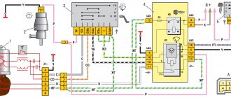
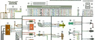
Factory colored electrical diagram (clickable 1900x1200)
What is connected by wires
The instrument panel displays information about engine operation and malfunctions, and indicators for turning on turn signals and headlights are located. The torpedo also has many functions. It contains buttons for turning on the foglights, side lights, headlights, heated rear window, and power window buttons. When engaged, reverse gear is signaled by the reversing lamps lighting up, also using electrical wiring and a sensor. The cabin sound alarm notifies about unfastened seat belts and lamp failures only thanks to wires. But that's not all! The generator, cooling fan, interior heater, and spark plugs also work thanks to the electrical wiring. All wiring harnesses originate from the fuse box and extend throughout the vehicle body.
Generator design
The second power source of any car is the generator. It is necessary to power all consumers when the engine is running. The generator consists of the following parts:
- Rotary excitation winding.
- Slip rings on the rotor.
- Bearings.
- Front and back covers.
- Stator winding.
- Voltage regulator.
- Pulley with impeller.
- Diode block.
- Capacitor.
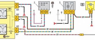
Front harness diagram for VAZ 2114 injector
The VAZ ignition module consists of a two-spark coil and is of the block type. The interior of the VAZ car has become more comfortable, a new, more convenient and advanced instrument panel has appeared, which has a more streamlined and ergonomic shape, backlit push-button switches and indicator lamps, etc. In the instrument panel wiring harness, the second ends of the white wires are brought together into one point, which is connected to the switch lighting of devices except for the white wire, from plug “4” of block “X2” of mounting block 28 to block 83 of the on-board control system indication.
The fuel supply is considered distributional, because gasoline is injected into each cylinder using a specific injector. The first coil supplies an impulse to the 1st and 4th cylinders, and the second - to the 2nd and 3rd cylinders.
Connecting the adsorber valve to the injection system controller also provided another additional element.
Peculiarities
VAZ 2114 cars have many innovations compared to 2109, in particular, this concerns electrical wiring.
Whether it is an injector or a carburetor, the wiring diagram for the VAZ 2114 is located in:
- vehicle interior;
- in the engine compartment;
- behind the car body.
It should be noted that carburetor VAZ 2114 were produced only from 1997 to 2000, then they were equipped with carburetors from the VAZ 2108.
But new engines have a more powerful ignition system; accordingly, the electrical control circuit is also characterized by certain features, for example:
- There is a new harness for connecting to the ignition module terminal. This component sends signals to the spark plugs through high-voltage wires.
- Another harness was added to allow mounting of the switch.
- Additional wiring has appeared to connect the adsorber valve to the injection system controller.
Many VAZ 2114 car owners mistakenly believe that thanks to the ignition module, they don’t have to use a coil. In fact, this device is equipped with two coils and two switches. One of the coils transmits the signal to the first and fourth cylinders, and the second - to the second and third.
The equipment system of VAZ 2114 cars with an injector engine has undergone certain innovations not only due to the addition of new electrical equipment, but also as a result of modernization of the car as a whole:
- it is possible to install a heated side mirror device;
- you can connect the front seat heating system;
- VAZ 2114 car owners can install PTF, etc.
Engine compartment
So that a VAZ 2114 with an injector engine can operate on a lean combustible mixture, the car is equipped with:
- forced gasoline injection system into each individual cylinder;
- connecting an improved ignition system characterized by higher power;
- added ECM - injection engine control system.
As is known, to ignite a lean combustible mixture there must be a more powerful spark transmitted through high-voltage explosive wires. A spark is transmitted through the explosives of the VAZ 2114 injector when the piston is located at top dead center. This control and connection scheme via high-voltage wires was implemented thanks to the installation of the module.
The operating principle of the device is as follows:
- a generator is used to generate alternating electric current;
- the current passes to the control unit, where it is converted into direct current;
- further, the current flows to the windings of the coils in accordance with the control circuit;
- the secondary winding begins to generate high voltage for transmission through high-voltage explosive wires;
- then, through the same high-voltage explosive wires, the voltage passes to the spark plugs.
Salon
As for the interior, the manufacturer replaced the center console in the VAZ 2114, which has certain differences:
- there is no longer a glove compartment in the upper part, it is installed lower;
- the dashboard was replaced;
- an on-board computer appeared in the VAZ 2114.
As a result of such changes and the replacement of old elements with new ones in the VAZ 2114 with an injector engine, the control and wiring diagram also changed:
- another harness appeared for connecting the on-board computer;
- a sensor for monitoring the temperature level outside the window has been added, which is mounted in front of the radiator;
- A voltmeter relay has been added.
In addition, another block of wires was added to the control circuit to control the power windows.
Signs of trouble
There are several types of electrical circuit conditions in Gazelle 405 euro 2, 402, 406, 4216, 2705, 3302 or business diesel cars:
- The engine does not start. A car cannot perform its primary function if the engine is not running. Either the wiring on the Gazelle business diesel, 402, 406, 405 euro 2, 4216, 3302, 2705 is damaged, or one of the units or mechanisms of the car has failed.
- The car engine starts, but the electrical equipment functions incorrectly or intermittently.
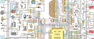
Wiring diagram for a Gazelle 405 car
If, as a result of an attempt to start the engine, the unit does not start, but fuel enters the engine, then most likely the problem lies in the electrical equipment:
If the vehicle is equipped with a carburetor, first you should pay attention to diagnosing high-voltage cables and spark plugs. By the way, quite often on older Gazelle cars with a carburetor, in practice, high-voltage wires cause inconvenience to the driver
If the high-voltage cables have exhausted their service life, the engine will not operate correctly. So check them first. On a Gazelle with a carburetor, it would not be a bad idea to check the performance of the distributor and coil. In addition to high-voltage wires, you can diagnose the electrical circuit in the engine compartment. In the case of an injector, the situation is slightly different. Of course, high-voltage wires can also cause breakdowns, but first of all you need to pay attention to electrical equipment. In particular, you are interested in the engine management system. If the injector control system is not able to properly process the pulses coming from the regulator, then as a result it will not be able to give commands to other components and mechanisms. Accordingly, interruptions in engine operation will begin.
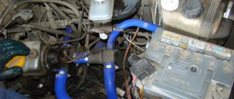
Electrical wiring of the engine compartment
As practice shows, in most Gazelle business diesel cars, 402, 406, Euro 2,405, 3302, 2705 and others, the causes of breakdowns are acidified or burnt contacts. In this case we are talking about the contacts in the ignition switch. If the ignition switch or unit is inoperative, at least the lighting in the vehicle interior will not be able to work. Also, faulty electrical equipment can lead to inoperability of washers, fans, windshield wipers, etc.
Electronic control unit
The wiring diagram of the VAZ-2114 ECU turns out to be very complex, since a large number of sensors and actuators are connected to it.
- Housing made of plastic and metal.
- At the heart of the circuit is a microcontroller.
- Sensors are connected to the microcontroller inputs through matching devices.
- Signal amplifiers, electronic keys and relays are connected to the controller outputs.
The microcontroller allows you to send signals to the actuators, depending on how the engine is operating. The ECU memory contains the algorithm for the operation of all systems. Moreover, the wiring diagram of the VAZ-2114 (injector) 8 valves differs from the V16, since a little more parameters are needed to control the engine.
Ignition module VAZ 2114
The ignition module is an important and responsible device in the 2114 ignition system. If it fails or is unstable, the following symptoms will appear:
- unstable idle speed;
- failures when changing engine speed;
- The second and third or first and fourth cylinders may not work in pairs.
If the first three signs can sometimes be attributed to incorrect ignition installation, then a paired failure of the cylinders only indicates a failure of the coil.
The principle of operation of the ignition module and its tasks are the same as those of the ignition coil, only the module also distributes high voltage current between the cylinders. It supplies sparks in pairs to 1/4 and 2/3 cylinders. In more finely organized ignition systems, each cylinder has its own coil, but the 2114 module is also capable of providing a spark to the cylinders in the order of their operation - 1-3-4-2
When working with the ignition module, it is important not to mix up the wires. The required cylinder is marked on the module body, so if you are careful, an error is excluded
The ignition module cannot be restored, so it must be checked for functionality especially carefully. If the device shows signs of incorrect operation, the computer displays the corresponding error codes: P0351 indicates that the coil of the first and fourth cylinders is not working, and P0352 indicates that the coil of the remaining two cylinders is not working. You can also check the resistance of the coils for insurance. If they are working, then at the input of paired cylinders (1-4 or 3-2) the ohmmeter will show 5.4 kOhm. Otherwise, the module has served its purpose. A new device costs about 1000 rubles.
We touched only on a few faults in the VAZ 2114 electrical wiring system. The rest will be helped by the diagram above and intuition, without which any repair is impossible. Good luck on the roads!
Troubleshooting
When troubleshooting, it is prohibited to connect the wires to body ground, as this leads to burnout of the tracks in the fuse box. It is also not allowed to use a screwdriver, knife, or awl when replacing relays and fuses.
VAZ-2114 wiring faults are divided into two types:
- Problems with the ignition system.
- Sensor malfunction.
Depending on the type, the diagnostic procedure is determined.
With the first type of malfunction, a loss of engine power, jerking, operation on three spark plugs, and unstable speed may be observed. In this case, you need to start by searching for a spark - unscrew the spark plugs one by one and connect them to the body or engine. If there is no spark, then the ignition module, coils and ECU are checked. The resistance on high-voltage wires should be within 5.4 kOhm. If the indicators do not correspond, then this is where the fault lies.
In the second option, you should check the connection of the wires by moving the contacts. If the test does not produce results, then you should move on to diagnosing the control sensors - check the malfunction of the sensors using a multimeter, measuring the resistance at the contacts. If the engine does not start, and the pressure in the fuel system is normal, there is a spark on all four cylinders, and the timing belt is intact, then most likely there is a problem with the crankshaft position sensor. In most cases, their malfunction is indicated by the corresponding lamp on the instrument panel. But a breakdown of the mass air flow sensor and idle air control can only be determined through diagnostics. The fault can also be identified using a diagnostic adapter, if available.
Engine starting system
The wiring diagram of the VAZ-2114 (injector and carburetor if in the power system) must have a starter. It helps the engine start. In this case, the battery acts as a power source.
- Stator winding (fixed part).
- Rotor winding (excitation).
- Bendix - designed for mechanical connection of the starter rotor and the flywheel crown on the crankshaft. Consists of a drive fork, overrunning clutch and gear.
- Solenoid relay - drives the bendix and power contacts.
- Covers, brush assembly and other parts.
Signs and causes of malfunctions
What “symptoms” can be used to identify problems in the electrical circuit of the injection VAZ 2114:
- Can't start the engine. If the malfunction is related to the electrical network, then the cause should be sought in the battery or generator.
- Generator belt whistling from under the hood. The strap may whistle due to high humidity when starting the engine, but if it makes sounds uncharacteristic of its operation every day, then you need to check the condition of the product. The fact that it will soon break can be indicated by traces of damage and defects on the structure.
- The battery light on the car's dashboard came on. It should always appear when the ignition is turned on. But if the lamp continues to light with the engine running, you need to check the performance of the battery. The reason for the appearance of the indicator may be due to problems with the generator.
- A burning smell in the car interior. Perhaps its presence is due to overvoltage in the electrical network. When high currents are passed through wires that the circuits are not designed to handle, the insulation layer can melt, resulting in an unpleasant odor. To troubleshoot, you need to ring the wiring and find the damaged area.
- Electrical equipment is not working correctly. For example, when the front optics are activated, the driver notices that the headlights are either shining normally or too dimly.
- There is damage to the battery case or lack of liquid in the cans. If the battery has cracks, electrolyte solution may leak through them. Its deficiency will lead to incorrect functioning of the battery and its complete failure.
What reasons could cause such problems:
- Generator failure or incorrect operation. The generator device may function intermittently if it fails. Installation failure is often associated with a broken drive belt.
- The battery is discharged or fails. Failure may be due to shedding of plates inside the structure. There is no way to fix this problem; the only solution is to replace the battery. If the battery is discharged after a long period of inactivity, then it simply needs to be recharged using a charger. When charging, it is recommended to unscrew the cans located on top.
- Contacts. Often the cause of malfunction of sensors and other devices is damage, oxidation or burnout of contact elements on connectors and plugs. Damaged components must be replaced, as well as burnt ones. Or you can try to clean them, which helps solve the oxidation problem. If the contacts are burned out, it is necessary to determine the cause, since this is due to voltage surges in the on-board network. Oxidation is usually associated with high humidity.
- Broken wiring. If the electrical circuit is damaged, it must be replaced. Often the wires fray and break off in the area of the rubbing elements of the body. It is recommended to lay electrical circuits so that they are not affected by friction.
- Leakage current. The problem is related to damage to the insulating layer on the wires. To fix the problem, you will need to find the defective area and replace it or re-wrap it with electrical tape.
- Fuse failure. Fuse elements are used to protect wiring and electrical equipment from overvoltage. If there is a surge in the network, these devices or relays are the first to break. To solve the problem, you need to find the blown fuse and replace it with a new one. A breakdown can be determined by a break in the fusible circuit located in the plastic case.
- Failure of the equipment itself. All devices have a certain service life, after which the devices fail. For example, the electric motor of a stove or cooling system fan, a car radio, a rear window heating device, etc. may break down. You can try to repair the equipment by removing it and disassembling it, but if repair is impractical, then the devices must be replaced.
Car electrical wiring design
The general wiring diagram of the VAZ-2114 can be divided into several components:
- External lighting system.
- Ignition system.
- Fuel supply.
- Engine control (sensors, actuators and ECU).
- Starting the engine (starter).
- Power (battery and generator).
- Additional equipment systems - wipers, washer, heater, heated mirrors, seats and windows, cigarette lighter, etc.
Absolutely all circuits that are connected to the battery are protected by fuse links. They are installed in the mounting block under the hood (as on its predecessor, the VAZ-2109).
Switching occurs using electromagnetic relays. They allow you to get rid of the flow of large current through the buttons when turning on powerful consumers. The reason is that when direct switching of high currents occurs, the buttons are destroyed and the contacts burn. In this regard, electromagnetic relays are much more reliable.
Self-repair of electrical equipment VAZ 2114
The simplest malfunctions that can happen to the electrical equipment of the VAZ 2114 can easily be eliminated with your own hands. Some even without special equipment. Here are just a few examples of the most common breakdowns and malfunctions.
If the battery discharges too quickly, it is worth checking the charging voltage at its terminals. To do this, you need to start the engine and use a multimeter to take readings from the battery terminals. The normal battery charging current is 12-14 volts. If the terminal voltage at idle speed of the engine is less than specified, then the battery will not charge to its rated value. The reason for this may be either a tired generator or a relay regulator. First, you should check the tension level of the generator drive belt. If the belt tension is insufficient, then at high speeds or in wet weather, when moisture gets on the drive belt pulleys, the belt may slip, and then the generator speed will be insufficient to fully charge the battery.
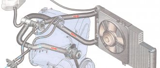
How does a generator work?
When the engine is stopped, the rotor winding is powered. Therefore, there is a magnetic field around it. But since the rotor does not rotate, the field is stationary. Therefore, one of the mandatory operating conditions of the generator set is not met - the magnetic field must be constant and moving. All conditions are met only when the starter begins to spin the crankshaft. In this case, the generator generates voltage supplied to the battery.
But the design feature of any car generator is that it produces alternating current. Moreover, three phases appear at the output, and alternating direct current is needed to power all consumers. Otherwise, all the sub-panel wiring of the VAZ-2114, the diagram of which is presented below, will simply burn out.
To rectify alternating current, a block of semiconductor silicon diodes is used. The design of a generator with three phases at the output is used for one simple reason - there is much less ripple. A capacitor is installed at the output of the rectifier - with its help it is possible to get rid of the entire alternating component of the current.
Types of power units
The manufacturer of Gazelles business diesel, 402, 405, 406, 2705, 3302 and other models is the Gorky Automobile Plant.
Initially, two types of engines were used in the production and assembly of vehicles:
- carburetor engines produced at UMP;
- injection and carburetor engines supplied by ZMZ (Zavolzhsk enterprise).
Gazelle car diagram
The essence of this approach was to modernize and unify power units for business diesel models, 402, 405, 406, 2705, 3302 and others with UAZ and Volga vehicles. Of course, in the case of trucks, the electrical circuit diagram was redone.
For certain types of motors, different schemes were used:
- In vehicles with an internal combustion engine injector, the operation of the fuel mixture ignition system was initially more demanding in terms of operation. Such units were equipped with electronic ignition elements and injection control units. Of course, in such units the quality of the fuel plays an important role.
- As for carburetors, such options are considered more traditional today, but they also have certain features. Of course, the wiring diagram in carburetor engines is different from injectors.
In addition to the main models 402, 405, 406, 2705, 3302 and others, since 2001 the manufacturer began to produce a version called “business diesel”. In the case of a diesel engine, the wiring diagram has also undergone certain changes. In particular, such vehicles began to be equipped with a more powerful starter, battery, and generator (video author - MR. BORODA).
How does a starter work?
The starter is powered directly from the battery - a wire goes from the upper terminal of the solenoid relay to the positive terminal of the battery. The launch system works according to the following scheme:
- When you turn the ignition key, power is supplied to all components of the fuel system, the ECU.
- When the key is set to the “Start” position, power is supplied to the control output of the traction relay.
- The pull-in windings create a magnetic field, which causes the core to move.
- The power contacts close and the rotor begins to rotate.
- At the same time, the Bendix moves along the rotor axis, and the gear engages with the ring gear on the flywheel.
- The crankshaft begins to rotate, fuel is injected into the combustion chambers and high voltage is supplied to the spark plug electrodes.
This is exactly how the entire engine starting system of any car works, including the VAZ-2114.
Oxygen sensor repair
Let's start with malfunctions of the oxygen sensor, and the VAZ 2114 wiring diagram for the injector will provide us with all possible assistance. If you don't know what the circuit is for, read this article. The most common causes of its breakdowns are a broken chain or the formation of carbon deposits on the working surface.
And the consequences that occur due to its breakdown look something like this:
- reduction in engine power;
- increased fuel consumption;
- failures during acceleration;
- tripling, etc.
It is not always easy to determine a possible malfunction in this sensor. The computer generates an error signal when there is a break in the circuit. But it may be the degree of his sensitivity.
Tip: to make a conclusion about replacing the sensor, let's start by checking the power supplied to it. Open the hood and disconnect its connector located on the cooling pipe.
Sensor appearance
To check it yourself, we need a tester:
- Let’s connect its “minus” to the motor, and attach the positive terminal to contact “B”.
- When the ignition is turned on, the tester will output 12 volts, otherwise this will mean that the battery is discharged or there is a break in the power circuit.
- Another reason could be a malfunction of the control unit, which is immediately confirmed by the on-board computer.
Note! To determine whether the sensitivity has disappeared, you need to connect the positive contact to output “A” and the negative contact to “C”. If the voltage between the 2 contacts is 0.45 V, then the circuit is in order
Otherwise, there is a fault in the power circuit.
In order to accurately check your oxygen sensor (see photo), you will need to enrich or lean the fuel mixture while simultaneously measuring its indicators. In any case, the operation of the sensor should not exceed 100,000 kilometers, after which it should be changed in any case, since this will be associated with unnecessary fuel costs.
Sensor installation location
- If the computer indicates the following error as "low signal", it will mean that the mixture is too rich.
- If the signal level is high, then the mixture is too lean.
Note! These errors indicate the composition of the combustible mixture, but not the serviceability of the oxygen sensor itself. Analyze whether there are air leaks and measure the fuel pressure, but only then look at the sensor itself
Replacement procedure
The instructions for replacing the regulator will not seem too complicated, especially if you use the tips below:
- it is necessary to place the car in a pit and remove the engine protection;
- disconnect the oxygen sensor, as described above, by disconnecting the connectors;
- remove the sensor with a wrench set to “22”.
Tip: if the sensor is too stuck, spray it with WD-40 from a bottle. You can heat the sensor and unscrew it while heated. Light tapping with a hammer may help.
The sensor is installed in the reverse order (see video). After tightening, the connector is connected. The sensor is fastened to the cooling system pipe with a clamp, after which protection can be installed.
Using the idle speed controller, automatic adjustment and stability of engine speed is maintained while the machine is stopped. It is based on a stepper electric motor equipped with a conical needle. Install it on top of the throttle body, near the throttle sensor. Attaches with a pair of screws.
As soon as you start the ignition, the rod extends and it rests against the calibration bell of the throttle pipe. The algorithm included in the operation of the sensor is designed to return the valve to its original state.
The electrical wiring of the VAZ 2114 works in such a way that a warm engine means that the regulator is located at a level in the range of 30-50 steps. Based on the location of the rod, the volume of air that enters through the calibration hole will also change.
As soon as the pitch decreases, the rod will retract. A single move can be up to 250 steps. If you need to replace the sensor and you purchase a new one, then do not forget to measure the distance between the flange and the rod head, which should be equal to 23 millimeters.
Voltage regulator operation
But there is one huge problem - depending on the crankshaft speed, the generator can produce voltage from 10 to 30 Volts, and such a variation is unacceptable. Therefore, it is necessary to stabilize the voltage at the same level - 12 V. In fact, of course, the generators produce a little more - 13.6-14.6 V. Only in this case will the battery be charged normally. You can stabilize the output voltage, but the problem is that the current consumption is very high.
And the zener diode must have considerable dimensions and, accordingly, cost. But it is much easier to stabilize the power supply to the rotor winding. If the voltage applied to it is stable, then the magnetic field will not change under any circumstances. This action is carried out using a voltage regulator. The maximum current consumption of the excitation winding is no more than 2 A. Structurally, the regulator is combined with a brush assembly.
Summarizing
As can be seen from the description, repairing the electrical wiring and equipment of the VAZ-2114 is not very difficult. Every self-respecting car enthusiast must know and understand the design of his car. This knowledge helps prevent serious car damage and avoid financial losses. After all, it’s no secret that a wiring fault can lead to a short circuit and fire in the car.
But if you do not have the skills to work with electrical equipment, and you could not figure out the designation and purpose of the wires, then you should contact a qualified specialist to avoid damage to yours or someone else’s property.
https://youtube.com/watch?v=videoseries