Chassis features
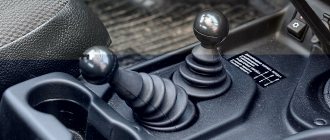
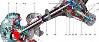
The VAZ Niva 2121 (21213, etc.) has both drive axles, which allows the car to efficiently overcome off-road conditions or muddy roads. Engine power is transmitted to each wheel through gearboxes. Niva has two of them: rear driven and front driven/steered.
These nodes are considered one of the most “painful”. If the car is actively used in extreme conditions, the first breakdown will occur at approximately 100,000 km. The modern market and service offer to immediately buy a new node. However, repairs are quite accessible with your own hands.
Definition of failure
A broken gearbox, like any other component, has specific signs of a defect. A competent auto mechanic can easily determine even the specific type of problem. An ordinary car owner should also know these signs so as not to spend money on car services. An audible way to determine gearbox damage:
- You should choose a road with the highest quality surface without traffic. You need to gradually accelerate to 90 km/h and brake smoothly. At this time, record the appearance of extraneous noise. Repeat the acceleration to 90 km/h, turn off the engine and listen while rolling. If the sound is different, then a breakdown is quite possible.
- Put the car on the hand (parking) brake, start the engine and gradually increase the speed in neutral gear. If the noises match the first test, then the gearbox is most likely normal.
A more accurate determination of the malfunction is possible on the lift when the wheels rotate freely. This method is best known to specialists from services. Using it requires experience and an understanding of what you need to hear.
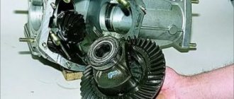
Front axle gearbox
The front gearbox of Niva 21213 differs from the rear gearbox: location, mounting method and design. In order to dismantle it, you will have to lift the car. Further analysis proceeds according to the following scheme:
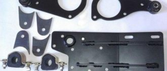
- Remove the front axle suspension extension (unscrew both fasteners).
- Unscrew the adjusting hub nut and remove the lower shock absorber mount.
- Install the stop and release the ball joint (lower) from the lever.
- Pull out the shank.
- Unscrew the engine support and the axle mounting.
- Unscrew the fastening of the inner joint bearing cap and crankcase bracket to the bridge.
- Pry off the cover and remove the housing from the gearbox.
- Using a support, separate it from the left engine bracket and the cylinder block. Remove the gearbox from the front axle mountings.
After this, you can disassemble the gearbox itself and accurately determine the nature of the damage.
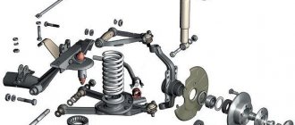
Removing front wheel drives
First, the preparatory work: I lift the front on chocks, remove the wheels, brake calipers (two bolts on the inside of the hubs), unscrew the hub nut.
After this, you can begin to remove the front wheel drives. I'll start with the left drive. Not because it’s correct, but it’s simply easier to remove, there’s no such problem as with the right one.
Before disassembling the front drive, you need to drain the oil from the gearbox!
How to remove the left front drive on a Niva
I unscrewed the nuts securing the ball joints (in the note about the link to: replacing the brake hose, you can clearly see it), and tapped the levers. The upper ball joint popped out of the lever (1 in the photo below), and the lower one failed. I was embarrassed to knock too hard, and it was inconvenient to knock on it, so I completely unscrewed the ball joint from the lower arm (remember to put the nut back in place later), three bolts with nuts (number 2 in the photo).
I remove the hub from the drive and move it to the side, let it hang on the steering rod. She doesn't bother me there.
The next step is to unscrew the flange securing the drive to the gearbox and try to tug lightly on the CV joint, the left one came out slowly. If he doesn’t want to come out himself, you can tap on his ears. Through some kind of block, the ears are between the bolts (in the photo below, an arrow marks one of these).
At first I didn’t want to pull the drives out completely, I just thought about pulling them out of the gearbox. I just need to remove the gearbox! But then I remembered that I would have to assemble it later, and in order to install the gasket between the drive flange and the gearbox, I needed to clean the remains of the old gasket from the flange and degrease it. It will be inconvenient to do this on site; it is easier to pull out the drive completely.
In order to pull out the drive, you need to unscrew the shock absorber mount from below, gently compress it (it simply won’t work sharply) and move it a little to the side. The top mount allows you to do this. The photo below shows the compressed shock absorber on the right side:
After this, the drive can be easily pulled out. You can check the condition of the CV joints, change the boots, or do nothing, like I did this time!
Right front drive, Niva
We begin to remove the right drive in the same way as the left one: unscrew the ball joint nuts, knock the hub out of them, then remove the hub from the drive and move it to the side on the steering rod. We unscrew the three nuts securing the drive flange, and then a surprise from the developer: the flange does not come out until you unscrew the bracket securing the gearbox to the engine:
The nut is welded to the bracket; you need to unscrew the bolt from above. In order to unscrew this bolt, you will need, in addition to the usual 19mm socket and wrench, an extension and a universal joint:
The bolt itself is located at the bottom right side of the engine:
Only after this bolt has been unscrewed can the right drive be pulled out of the gearbox.
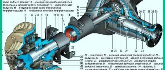
Rear axle
A diagram of dismantling the unit will also be described below. Specific repairs to the rear axle gearbox of the VAZ 2121 Niva require specifics. It is simply impossible to briefly describe every possible malfunction and its elimination. Therefore, the diagram for removing the rear assembly is:
- Unscrew the axle shaft.
- Bend back the locking plates.
- Move the axle shaft.
- Remove the mounting bolts and remove the assembly.
As you can see, the rear assembly is much easier to remove. All that remains is to secure it on the workbench and disassemble it. However, you still need to remember that the part is very heavy and move it carefully.
content .. 61 62 ..3.5.2.
VAZ-21213 (Niva). Removing and installing the rear axle
GENERAL INFORMATION PERFORMANCE ORDER
1. To remove the rear axle, it is enough to disconnect the suspension rods and shock absorbers only from the rear axle beam. 2. When installing the rear axle, tighten the nuts of the rod mounting bolts in accordance with the instructions in subsection 4.2.2. 3. After installation, bleed the brake system and adjust the service and parking brake systems according to the instructions in subsection 6.2. 4. Fill the rear axle with transmission oil through the oil filler hole.
3.5.3.
VAZ-21213 (Niva). Dismantling and assembling the rear axle
GENERAL INFORMATION Disassembly PERFORMANCE
ORDER 1. Remove the pipeline with the brake system tee from the bridge, while disconnecting the ends of the tubes from the brake wheel cylinders.
2. Place the axle on a repair stand and drain the oil from the crankcase. 3. Having removed the brake drum and unscrewing the nuts securing the brake shield using ejector 67.7823.9516 – 2, remove axle shaft 1 complete with oil deflector, bearing mounting plate, bearing and lock ring.
4. Remove the brake shield and O-ring. 5. If replacement is necessary, remove the oil seal from the bridge beam flange. 6. Perform the same operations on the other end of the beam, then remove the gearbox. Assembly PERFORMANCE
1. Assemble the rear axle in the reverse order of disassembly. 2. Lubricate the threads of the gearbox mounting bolts with sealant, having previously degreased them and the threaded holes in the rear axle beam. 3. Before installation, coat the axle bearing oil seal with Litol-24 grease, and when installing the oil seal in the beam flange, use mandrel A.70157. 4. Lubricate the seating belt of the axle shaft and the surface of its flange in contact with the drum with graphite grease or LSC-15 grease. 5. Install the brake drums after installing the rear axle on the vehicle and securing the cable ends to the parking brake drive levers.
3.5.4.
VAZ-21213 (Niva). Checking the rear axle beam
GENERAL INFORMATION EXECUTION ORDER
1. Carefully check the technical condition of the beam, especially when repairing a car that has suffered an accident. A deformed beam can cause rear axle noise and accelerated tire wear. 2. The deformation of the bridge beam is checked in both horizontal and vertical planes. 3. Having attached flange A.70172 to each end of the beam, install the beam with flanges on identical prisms located on a test plate at least 1600 mm long so that the contact surface of the crankcase to the beam is in a vertical plane.
| 4. Check the deformation of the beam by placing a square against the outer surface of the A.70172 flange. |
| 5. Check the deformation of the beam by placing a square against the side surfaces of the flange. If the beam is not deformed, the square will fit tightly. The amount of deformation is checked with a feeler gauge. If the 0.2 mm feeler gauge passes on any flange, the beam must be straightened. |
| 6. Using a square, check the perpendicularity of the gearbox mounting surface relative to the supporting surface of the A.70172 flange. The 0.2 mm probe should not pass through. |
7. Rotate the bridge beam 90° and install it on the prisms.
| 8. The square applied to the outer surface of the flange must fit tightly, otherwise check the amount of deformation with a feeler gauge. The 0.2 mm probe should not pass through. |
9. If deformation exceeds the specified amount, straighten the beam following the instructions below. 10. After making corrections, thoroughly rinse the beam, clean the magnetic plug, install it in place and check the quality of the welds and the tightness of the beam and the cleanliness inside the beam (no burrs, chips and oil residues) and the cleanliness of the beam breather. 11. After this, paint the outside of the beam to protect it from corrosion.
3.5.5.
VAZ-21213 (Niva). Editing the rear axle beam
GENERAL INFORMATION Scheme for straightening the rear axle beam
| 1 – hydraulic cylinder; 2 – clamping beam; 3 – flange A.70172; 4 – square; | 5 – press table; 6 – emphasis; 7 – indicator stand |
PERFORMANCE ORDER
1. Attach A.70172 flanges to each end of the beam (used for straightening, not for checking beams) and install it on the supports of the hydraulic press so that the ends of the clamping crossbar 2 are in the deformation zone. The most likely location of the zone is at a distance of 200–300 mm from the ends of the beam flange (see Fig. Rear axle beam straightening diagram). 2. Install the stand 7 with the indicator so that the indicator leg rests against the upper part of the side surface of the flange, and the indicator arrow stands on a mark equal to the amount of deformation of the beam measured with a feeler gauge when checking the beam. On the other side of the beam, install either a stand with an indicator or a square 4. 3. Having installed limiting stops 6 under the beam (in the deformation zone), use a hydraulic press to straighten the beam sequentially in the horizontal and vertical planes, monitoring the straightening results using the indicator or a feeler gauge using square 4. 4 The maximum press force during straightening of the beam should not exceed 98 kN (10,000 kgf) so that excessive deformation of the casing section does not occur. 5. Remove the beam from the press and check it as indicated above, replacing the A.70172 flanges with “test” ones. 6. In the absence of proper equipment, as an exception, it is allowed to edit the rear axle beam sequentially on each side, but with mandatory checking of deformation on both sides (see subsection 3.5.4).
content .. 61 62 ..