Adjusting the headlights on the Lada Kalina does not require complex manipulations or special knowledge. The car enthusiast is able to make the adjustment with his own hands. First of all, you need to remember that the adjustment of the optics is related to the elements of the Kalina chassis, the pressure inside the tires and the condition of the light bulbs. It is necessary to replace darkened lamps and adjust the pressure (it should be the same for each side of the machine).
Adjustment of Kalina's lights takes place with a fully filled tank, a standard spare wheel and a set of tools.
Tools for checking and adjusting light lights on the Lada Kalina:
- tape measure, 5 meters is enough;
- large sheet of cardboard or plywood;
- five-millimeter 6-sided key;
- load not less than 75 kg;
- pen-pencil);
- opaque textile (piece of black fabric).
Stages of adjusting Lada Kalina lighting fixtures:
- Drive the car up to a smooth wall, strictly perpendicular, and stop at a distance of 5 meters. Place a load on the driver's seat.
- Place a plywood screen with a diagram for adjusting the headlights against the wall. Apply three vertical stripes on the diagram: an axial one and two lines corresponding to the centers of the low beam bulbs, symmetrical to the axial one. Two horizontal stripes: the first corresponds to the middle of the headlights (counting from the bottom), the second should be drawn 75 mm lower - this is the central position of the light beam.
- Set the Kalina headlight corrector to zero and turn on the low beam.
- The lighting devices on Kalina will be adjusted when the upper line of the light strip is located on the lower (second) horizontal line. The edges of the light beam boundaries should be located along the outermost vertical stripes. If the actual position of the light spot does not correspond to the adjustment parameters, open the hood, find the adjustment screws and make the correction (by tightening or loosening the fasteners). There are two screws for each headlight. One is responsible for the horizontal plane. Using the second, you can raise or lower the light beam.
- The correct location of the light window is adjusted separately for each headlight, while the second one is covered with thick textiles.
The PTF on the Lada Kalina is adjusted in a similar way. The border of the light flow should be located half a meter below the level of the headlights.
It is important to pay attention to the correct location of the headlights on Kalina, including PTF. With the correct placement of the optics, the driver automatically avoids emergency situations that arise in cases of poor road illumination at night, during fog, rain and snowfall, or due to the glare of oncoming traffic.
The adjustment process on Kalina itself is not too long and does not require any special skills; most car enthusiasts can handle it on their own. If you don’t dare to carry out the procedure yourself, you can go to any service station where specialists will be happy to help.
Operating principle
The corrector is designed to adjust the level of the cut-off line in low beam headlight mode. For the long-range glow mode, this option is not so important, since only the low beam headlights have a clear cut-off line (the conventional border of the light flux, abruptly turning into a practically unlit area). The low beam of the headlights should illuminate the road well, but not dazzle oncoming drivers.
The level of the cut-off line depends on the shape and vertical angle of the reflector. It is the last parameter that needs constant adjustment, since the angle of the headlights depends on the degree of load and distribution of cargo in the car. The more the rear part is loaded, the more the front of the car will be raised. Accordingly, even correctly adjusted headlights will now blind drivers of oncoming cars.
According to the requirements for cars manufactured in Europe, all cars approved for operation after 1999 must be equipped with a headlight leveler as standard. Such systems are not installed on cars with active suspension.
Enforcement systems
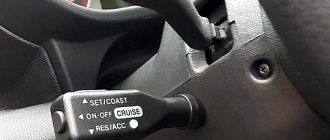
The headlight range control is controlled by changing the position of the switch on the dashboard. The main types of drives used in the design of manual correctors:
- mechanical. The design can only be called a headlight corrector, since the device is an adjusting screw mounted in the headlight housing. Screwing or unscrewing the latter leads to a change in the vertical angle of inclination of the reflector;
- hydromechanical;
- electromechanical;
- pneumatic. Due to its complexity, the pneumatic headlight leveler has gained little popularity. The system can have manual or automatic adjustment. In the first case, the pneumatic actuators are controlled by the driver via an n-position switch on the dashboard (most often used in conjunction with halogen lighting). The operation of the automated system involves body position sensors, a control unit, and actuators (used in conjunction with xenon lamps). The position of the reflector is regulated by changing the air pressure in the corresponding lines.
Hydrocorrector
This system is well known to domestic car enthusiasts, since manual headlight levelers of this type were installed on VAZ 2107, 2109, 2110, 2114, Niva, and Granta.
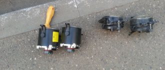
Main components of the system:
- 6 – knob for adjusting the light beam;
- 1 – main adjustment mechanism;
- 2 – working cylinders with a rod acting on the headlight reflector.
The operating principle is based on adjusting the position of the corrector rod by moving a special fluid along the lines. The switch is mechanically connected to the piston of the main hydraulic cylinder. When the regulator handle is operated to raise the reflectors, the fluid pressure in the system increases, which drives the working cylinders, thereby extending the rod. Since the system is completely sealed, moving the handle back has the opposite effect.
The archaic system is considered extremely unreliable. Over time, the joints of the tubes and cuffs lose their tightness, which leads to air being sucked into the system and loss of working fluid.
Electromechanical corrector
The electrically driven headlight reflector adjustment system has become the most widespread. The electric drive allows for both forced change in the height of the light beam boundary and automatic adjustment depending on actual driving conditions.
The device of the forced action system:
- switch on the dashboard;
- gear motors;
- Control block;
- power wires.
The switch is usually installed to the left of the steering column and has 3-4 fixed positions to change the angle of the headlight reflector. The servo drive, also known as the gear motor, which is also the headlight range control unit, is an actuator, the movement of the rod of which raises or lowers the reflector, resting on its lower part (the reflector is mounted on hinges at the top).
Principle of operation
In principle, the servo drive design resembles a gear motor used in the design of a central lock. Device:
- small DC motor with magnetic excitation;
- worm gearbox, used to convert the rotational movement of the electric motor shaft into reciprocating movement of the rod;
- control circuit;
- sensor of the actual position of the rod of a resistive type.
The ECU regulates the position of the rod by applying control voltage to the servo drive. Let's look at the control logic for headlight range control units with an electromechanical drive using the example of BUK 02-01, which is used on many domestic cars. One of the main components of the control board is a bridge control circuit for the geared motor, which is based on a two-channel operational amplifier. One arm of the bridge circuit is connected to the actual position sensor of the rod, and the second is connected to the input pin of the control board. The influence on the electric drive of the corrector is carried out by changing the control action at the input of the board. When a bridge mismatch error occurs, the control system will supply voltage to the servo drive until the voltage at the position sensor terminals is equal to the control one. The electronic control unit must provide protection against overvoltage of the vehicle's on-board network. When the electromechanical headlight range control switch does not change its position, the electric motor is off.
Typical faults
- Open circuit, appearance of oxides at connectors.
- Wear of electric motor parts.
- Burnout of integrated circuit elements.
Replacing head lamps
Each lamp has its own resource, the value of which depends on many factors. Over time, devices break down and require replacement. And then the question arises: how to disassemble the headlight?
The replacement procedure is simple, but before that you need to choose the right lighting devices from the mass of products offered on today's market. Although sometimes all you need is to replace the headlight glass.
So, if the headlights are purchased, then we change:
- Remove the protective cover from the headlight housing. It's rubber, so it's easy to pull off if you pull on one of the three tags.
- Disconnect the power connector.
- Release the spring clip.
- How to remove the headlight? We take out the lamp and install a new element in its place.
Attention! When replacing a halogen lamp, avoid touching the bulb with your hands. This may damage the device. Over time, greasy fingerprints will cause the glass to darken, causing the lamp to overheat and eventually burn out.
- If contact occurs, it is necessary to wipe the surface of the flask with a cloth moistened with alcohol.
- Changing side lamps
- We also remove the cover and disconnect the corresponding cartridge from the on-board network.
- We remove the lamp and install a new one in its place.
Automatic headlight control systems
The automated headlight reflector position corrector does not require driver participation to adjust the cut-off line. The system used with halogen lamps is based only on the position of the body, which is why it is also called static.
On vehicles with xenon light sources, an advanced adaptive corrector is used that maintains the light beam in a given position, focusing on changes in body position when accelerating, decelerating, changing direction and driving on bumpy road sections. This is determined by the fact that the direct light of xenon headlights has a much more aggressive effect on human eyes.
System design:
- vehicle ride height sensors;
- Control block;
- servo drives (conventional electromechanical gear motors).
Sensor from the kit for installing xenon yourself.
The operating principle is based on the constant reading of the vehicle's ground clearance. For this purpose, non-contact sensors based on the Hall effect are used. Typically, several sensors are installed on load-bearing body elements in the front and rear parts. The meter body contains a stator (moving element) with built-in magnets and a rotor (fixed element), which is a Hall sensor. The stator is connected by a rod to the suspension part, so any change in the position of the part relative to the body is transmitted by the sensor to the control unit. The ECU processes the received information and controls the operation of the gearmotors. Despite the obvious convenience, the automatic corrector is often equipped with a system with the possibility of manual adjustment.
Why bad light may occur on a VAZ 2114
To solve the problem, you need to understand all the nuances of the headlights. Simply replacing headlights may not give the desired effect. In some cases, changing lamps will be a waste of money.
Causes of headlight malfunction:
- One of the most common reasons is dirty windows. Dirt, which may appear on the headlights after prolonged use, can reduce illumination by approximately 50%. It also happens that it is quite difficult to notice any dirt on the headlights. This is due to the fact that they may not be noticeable. How to remove dirt from headlights? This may not be so easy to do, because using a dry rag is prohibited. It leaves small and unnoticeable scratches on the glass that can ruin the glass.
- Minor scratches are another common cause of dim headlights. Scratches can appear for a variety of reasons. The thing is that by wiping the headlights with a regular rag or even a glove or some item of clothing, you can actually clean the surface of the headlight, but small scratches will also appear on it. As long as the number of scratches is small, this will not have any serious effect on the performance of the headlights, but after a long time there may be so many scratches that the headlights will be exceptionally dim.
- In some situations, the glass may even burst. There are many reasons for this. In Russia and other CIS countries this can happen due to temperature. If a car enthusiast notices any crack, he needs to remove the headlamp as soon as possible and replace it with a new one. If this is not done, the headlight may stop working while driving. The consequences of unexpectedly turning off the lights can be unpredictable.
- Another reason for deterioration in illumination is the age of the headlight. Over time, the headlights become increasingly cloudy. This is due to the fact that while driving, various small debris, as well as sand and dust, fall onto the surface of the headlight. As a result, very small scratches begin to appear on them. Despite the fact that they are practically invisible, these scratches are capable of refracting light according to the principle of a prism. This is an extremely unpleasant effect. It is because of this that the glass has to be replaced. How to protect the headlight from such unpleasant consequences? In this case, it is recommended to cover them with a special protective film, which can be purchased at a car store.
How to adjust the headlights on a Lada Kalina with your own hands
From time to time, drivers encounter an unpleasant and dangerous moment - a light curtain. A wide, high beam from the vehicle's lighting illuminates the space in front of the car. This situation causes 30% of road accidents.
This is easy to avoid: it is important to systematically check and adjust the position of the lighting equipment on the car. This is not the most difficult task, and can be done independently without the involvement of specialists. The algorithm is universal for all machines. As an example, let's look at how the Kalina Lada headlights are adjusted.
Question and answer: what should not be allowed under any circumstances
Q: What happens if you buy lamps with a base other than “H7”?
A: It will not be possible to install lamps in a standard headlight.
Q: If I use more than 55 watts of power, will this cause overheating?
A: Excessive power leads to the fact that the fuse in the low beam lamp circuit burns out. A separate fuse is used for each of the lamps, so it will not be possible to “deceive” the automation.
Q: Are halogens afraid of power surges?
A: For incandescent lamps, excess voltage is a harmful factor. In the case of using halogen lamps, there will be two harmful factors: overheating, underheating. Actually, this is why MTBF can be considered a relative rather than an absolute value. This value depends, and depends strongly, on the stability of the voltage.
Headlight range control: device and malfunctions
A device that monitors and regulates the position of a car's lighting devices is called a headlight range control. It is possible to adjust the headlights on Kalina using:
- Kalina manual headlight leveler;
- electric headlight corrector.
The principle of operation in both cases is similar, the difference is one. The first option involves making the correction using a regulator installed inside the car. The driver himself changes the tilt of the car lighting. The electric corrector works automatically: depending on the location of the machine, the device changes the angle of inclination of the optics.
In 45% of cases, failure of optical devices is due to the fact that the corrector on the Lada Kalina does not work.
- Sensor inaccuracy. Failure of the bracket leads to a failure of the tracking element synchronizer performance.
- Souring of contacts. Due to the reduced conductivity of the electrical wire, the device begins to malfunction.
- Factory defect. The regulating element falls out of the electric corrector.
Reasons for adjusting headlights
Headlight position during final adjustment
Many car enthusiasts do not understand why and how to adjust headlights. According to regulation No. 699 of the “International Automobile Convention” of December 12, 1999, there are basic rules for the use of light at night. It states that car light must fall at a certain angle, offset to the right for left-hand drive cars, and to the left for right-hand drive cars.
It is for this purpose that headlight correctors are installed on the car. If they are not enough for full adjustment, then you need to adjust the light manually by adjusting the headlights using the mounts.
Another reason is the load on the car, the curb weight, as well as the number of passengers who regularly drive the car.
How to adjust headlights
Adjusting the headlights on the Lada Kalina does not require complex manipulations or special knowledge. The car enthusiast is able to make the adjustment with his own hands. First of all, you need to remember that the adjustment of the optics is related to the elements of the Kalina chassis, the pressure inside the tires and the condition of the light bulbs. It is necessary to replace darkened lamps and adjust the pressure (it should be the same for each side of the machine).
Adjustment of Kalina's lights takes place with a fully filled tank, a standard spare wheel and a set of tools.
Tools for checking and adjusting light lights on the Lada Kalina:
- tape measure, 5 meters is enough;
- large sheet of cardboard or plywood;
- five-millimeter 6-sided key;
- load not less than 75 kg;
- pen-pencil);
- opaque textile (piece of black fabric).
Stages of adjusting Lada Kalina lighting fixtures:
- Drive the car up to a smooth wall, strictly perpendicular, and stop at a distance of 5 meters. Place a load on the driver's seat.
- Place a plywood screen with a diagram for adjusting the headlights against the wall. Apply three vertical stripes on the diagram: an axial one and two lines corresponding to the centers of the low beam bulbs, symmetrical to the axial one. Two horizontal stripes: the first corresponds to the middle of the headlights (counting from the bottom), the second should be drawn 75 mm lower - this is the central position of the light beam.
- Set the Kalina headlight corrector to zero and turn on the low beam.
- The lighting devices on Kalina will be adjusted when the upper line of the light strip is located on the lower (second) horizontal line. The edges of the light beam boundaries should be located along the outermost vertical stripes. If the actual position of the light spot does not correspond to the adjustment parameters, open the hood, find the adjustment screws and make the correction (by tightening or loosening the fasteners). There are two screws for each headlight. One is responsible for the horizontal plane. Using the second, you can raise or lower the light beam.
- The correct location of the light window is adjusted separately for each headlight, while the second one is covered with thick textiles.
The PTF on the Lada Kalina is adjusted in a similar way. The border of the light flow should be located half a meter below the level of the headlights.
It is important to pay attention to the correct location of the headlights on Kalina, including PTF. With the correct placement of the optics, the driver automatically avoids emergency situations that arise in cases of poor road illumination at night, during fog, rain and snowfall, or due to the glare of oncoming traffic.
The adjustment process on Kalina itself is not too long and does not require any special skills; most car enthusiasts can handle it on their own. If you don’t dare to carry out the procedure yourself, you can go to any service station where specialists will be happy to help.
Source: infokuzov.ru
Adjustment features
Since Lada Kalina is a representative of the budget segment, it is equipped with a minimum of required lighting devices. Here we focus on head optical devices. Headlights allow the driver to have sufficient visibility when driving, and also serve to identify a specific car on the roadway.
This is interesting: How to paint a car bumper with your own hands?
Adjustment of the Lada Kalina headlight beam is carried out using a specialized device during a technical inspection. Mechanics advise owners to periodically check the correct beam and adjust the headlights (if necessary) and if necessary, know how to adjust the headlights yourself. The indicated procedure can be carried out independently.
The settings of the Lada Kalina lighting devices are interconnected with the condition of the load-bearing elements of the chassis, lamps and tire pressure. Before adjusting the lighting devices, it is recommended to check the points indicated here to ensure they are in good condition and that the indicator (pressure) is correct. If there are deviations from standard values, then the identified deficiencies should be eliminated immediately. For example, the pressure parameter should be the same on both sides of the car. Darkened lamps will also need to be replaced with new analogues.
To adjust the optics in the Lada Kalina, the owner will need the following tools:
- cardboard sheet;
- five-meter tape measure;
- "hexagon" (6 mm).
Adjustments should be made in a dark box or at the appropriate time of day. Also one of the main conditions is the presence of a vertical wall. We install the car on a level area five meters from the designated structure. We adjust the corrector to the zero position.
A cardboard sheet is required to periodically block the beam of headlights. The adjustment process itself is carried out using a hex key with a dimension of 6 mm. The light beam of each headlight is individually compared with a special circuit. Here it is necessary to achieve the correct direction of the beam, which will allow the driver not to dazzle oncoming traffic participants in the dark.
Operating principle
The corrector is designed to adjust the level of the cut-off line in low beam headlight mode. For the long-range glow mode, this option is not so important, since only the low beam headlights have a clear cut-off line (the conventional border of the light flux, abruptly turning into a practically unlit area). The low beam of the headlights should illuminate the road well, but not dazzle oncoming drivers.
The level of the cut-off line depends on the shape and vertical angle of the reflector. It is the last parameter that needs constant adjustment, since the angle of the headlights depends on the degree of load and distribution of cargo in the car. The more the rear part is loaded, the more the front of the car will be raised. Accordingly, even correctly adjusted headlights will now blind drivers of oncoming cars.
According to the requirements for cars manufactured in Europe, all cars approved for operation after 1999 must be equipped with a headlight leveler as standard. Such systems are not installed on cars with active suspension.
Enforcement systems
The headlight range control is controlled by changing the position of the switch on the dashboard. The main types of drives used in the design of manual correctors:
- mechanical. The design can only be called a headlight corrector, since the device is an adjusting screw mounted in the headlight housing. Screwing or unscrewing the latter leads to a change in the vertical angle of inclination of the reflector;
- hydromechanical;
- electromechanical;
- pneumatic. Due to its complexity, the pneumatic headlight leveler has gained little popularity. The system can have manual or automatic adjustment. In the first case, the pneumatic actuators are controlled by the driver via an n-position switch on the dashboard (most often used in conjunction with halogen lighting). The operation of the automated system involves body position sensors, a control unit, and actuators (used in conjunction with xenon lamps). The position of the reflector is regulated by changing the air pressure in the corresponding lines.
Installation of electric headlight corrector for VAZ 2114
There is nothing complicated in installing the electric headlight corrector on a VAZ 2114; it is installed in standard places instead of the hydraulic corrector and works on the same principle.
If your hydraulic corrector fails, it is better to immediately purchase a much more reliable electric corrector; there is nothing complicated in installing it:
- Remove the instrument panel light knob.
- Remove the hydraulic corrector handle.
- Use a screwdriver to pry up the lining with the corrector scale printed on it and remove it.
- Remove the light guide; it is fastened with a Phillips screw and ensures uniform illumination of the scale.
- The main cylinder is screwed with a nut 21, unscrew it and press on the cylinder, then remove it from under the instrument panel.
- To remove the working cylinders from the headlights, press the lock and turn it counterclockwise, after which it can be removed from the headlight housing.
- After cutting the tubes with side cutters, remove all parts of the hydraulic corrector from the car.
After all this, you can start installing the electric corrector on the VAZ 2114:
- Route the wire harnesses into the factory holes with rubber seals along the stock wiring.
- Insert the electric correctors in place of the hydraulic correctors into the headlight housings.
- Connect the wire block to them.
- Connect the negative wire to the vehicle ground, and the positive wire to the power that appears when the ignition is turned on.
- Connect the wire block to the regulator.
- Install the regulator in place of the hydraulic corrector master cylinder in the reverse order of removal.
Automatic headlight control systems
The automated headlight reflector position corrector does not require driver participation to adjust the cut-off line. The system used with halogen lamps is based only on the position of the body, which is why it is also called static.
On vehicles with xenon light sources, an advanced adaptive corrector is used that maintains the light beam in a given position, focusing on changes in body position when accelerating, decelerating, changing direction and driving on bumpy road sections. This is determined by the fact that the direct light of xenon headlights has a much more aggressive effect on human eyes.
System design:
- vehicle ride height sensors;
- Control block;
- servo drives (conventional electromechanical gear motors).
Sensor from the kit for installing xenon yourself.
The operating principle is based on the constant reading of the vehicle's ground clearance. For this purpose, non-contact sensors based on the Hall effect are used. Typically, several sensors are installed on load-bearing body elements in the front and rear parts. The meter body contains a stator (moving element) with built-in magnets and a rotor (fixed element), which is a Hall sensor. The stator is connected by a rod to the suspension part, so any change in the position of the part relative to the body is transmitted by the sensor to the control unit. The ECU processes the received information and controls the operation of the gearmotors. Despite the obvious convenience, the automatic corrector is often equipped with a system with the possibility of manual adjustment.
The design can use only one ultrasonic type body position sensor. Most often, this solution is offered as an alternative to standard systems when installing xenon lamps with your own hands.
Source: autolirika.ru
Electromechanical types of correctors
This type of device is high-tech, it is the most popular and widespread. Its design is simple, consisting of several elements:
- Geared motors for each headlight.
- 4 position switch.
- Wiring.
- Fuse.
If you use such a device, you will need to do the following:
- Remove (if installed) the hydraulic corrector drive.
- If you plan to install the switch in another location, then the first step is not necessary. The most suitable place to mount the switch is to the left of the steering wheel.
- Lay the electrical wiring to each headlight. It is advisable to connect the wires to the harnesses with special plastic ties.
- Install new stepper motors in place of the adjusting rods of the old hydraulic corrector.
- Connect the wires to the stepper motors.
- Since this device consumes, albeit a small current, it is necessary to install a 7.5 Ampere fuse in the positive gap of the power supply. This device will save you from a short circuit. But it is best to calculate the maximum current consumed by the entire system. Based on this value, select a suitable fuse with a margin of 25%.
How does headlight range control work on a viburnum?
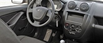
Lada Kalina Cross. LIGHTING CONTROL MODULE AND LOW BEAM CORRECTOR
External lighting switch (PLS) 1 (Fig. 34) has three fixed positions (or four in a variant version):
O - When the engine is off, the exterior lighting is off, when the engine is on, the daytime running lights (DRLs) are on;
-side lights combined with DRL are on;
– the side lights and low or high beam headlights are turned on, depending on the position of the light signaling switch (see the section “Light signaling switch”).
– in a variant, in this position, the side lights and low beam headlights turn on and off automatically depending on the state of external lighting. The light sensor is combined with a rain sensor and is located on the windshield behind the rear view mirror. The automatic control system for external lighting (lighting system) allows you to turn on and off the side lights and low beam headlights of the vehicle depending on the level of external light. For example, at dusk, as well as when entering a tunnel or garage.
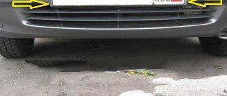
Traditional headlight removal
Access to all upper and lower screws will only be possible if the front bumper is missing. After removing the screws, you can begin to remove the headlight unit, but first you should get rid of the pads and wires. First of all, let's look at the technology for removing the bumper.
You can learn how to adjust headlights yourself by reading the detailed material from our specialist.
Another common question is how to replace a low beam light bulb. Our expert will help you understand this problem.
Bumper Removal Guide
The bumper should be removed according to the following instructions.
- Unscrew the screws securing the fender liners. There should be only four of them. Use a Phillips screwdriver.
- At the bottom left and right you need to remove one more screw.
- From below you also need to unscrew the three bolts that secure the bumper.
- Remove the radiator grille and begin unscrewing the bolts that secure the car bumper.
- Under the license plate you will find a decorative plastic grille; you also need to temporarily get rid of it. To remove it, just unscrew two bolts and apply a little effort, since additional fastening is provided by clamps. Don't be afraid to push yourself harder.
- It remains to remove two screws in the area under the license plates.
- To further remove the bumper, grab its edges on the sides and tear it off the latches, pointing it towards you. This element is quite light in weight, so you can handle it even without outside help.
Removing headlights
Assuming the bumper is removed, further steps to remove the headlights are as follows.
- It is necessary to remove the bumper power beam.
- The lower bolts that secure the headlight must also be removed. You won't find them right away, so tilt the beam slightly to the side and use a 8-mm ratchet to unscrew the two bolts.
- There are also two top bolts. A Phillips screwdriver will help you deal with the first one, and a 8-mm wrench with the second one.
- Disconnect the power plugs responsible for adjusting the height of the light beam and the lighting itself. The electrical adjustment plug is secured by a latch; do not forget to bend it.
- All you have to do is grab the headlight housing with both hands and remove it.
Notes:
Adjusting the position of the headlights must be done every 20 thousand km or as needed. On the Lada Kalina, this adjustment operation is not carried out often, since deviations from the norm rarely occur (in most cases, due to road accidents).
Checking and adjusting the headlights of the Lada Kalina VAZ 1118 is carried out with a fully filled fuel tank, a set of tools and a spare wheel.
1. First check the air pressure on all tires of the car with a pressure gauge. If necessary, bring it to normal.
2. Place the Lada Kalina car perpendicular to a smooth wall (for example, a garage) at a distance of 5 m. Place an additional weight weighing 75 kg on the driver’s seat.
3. Mark the screen on the wall as shown in the headlight adjustment diagram.
4. Draw a vertical center line O on the screen, lying in the plane of symmetry of the car (the distance from it to the center of the left and right headlights should be equal). To the left and right of it, draw two more symmetrical lines A and B , which should coincide with the centers of the left and right headlights.
5. At a height h corresponding to the distance of the centers of the headlights from the ground, draw a horizontal line 1, and 75 mm below it - line 2 .
6. Turn on the low beam headlights on the Lada Kalina car by turning the headlight range control of the Lada Kalina 1118 to position “0” (this position corresponds to the load of the Lada Kalina car with one driver).
7. Closing each headlight in turn, check that the light limit corresponds to the adjustment diagram previously marked on the screen. The boundary must follow line 2. The inclined segments must begin at the intersection points.
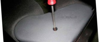
8. Insert the "6" hexagon into the regulator socket through the hole in the upper cross member of the radiator frame.
9. By turning the hexagonal adjuster 1 , located closer to the wing, adjust the position of the headlight beam in the horizontal plane.
10. By turning regulator 2 , located closer to the radiator, adjust the position of the light beam in the vertical plane. Make sure that the upper boundary of the light beam coincides with the lower horizontal line, and the break point of the beam (the point of intersection of the horizontal and inclined sections of the light flux) with the vertical line corresponding to the center of the headlight.
11. Similarly, adjust the direction of the light beam of the other headlight.
Note:
Adjust the direction of the light spot for each headlight separately. During adjustment, cover the second headlight with opaque material or disconnect the connector with wires from it.
Scheme for adjusting headlights on a Lada Kalina VAZ 1118 car:
- 1 – a horizontal line corresponding to the centers of the headlights;
- 2 – a line passing through the centers of light spots;
- A, B – vertical lines corresponding to the centers of the headlights;
- O – center line;
- h – distance from the centers of the headlights to the floor;
- d – distance between the centers of headlight lamps.
The procedure for dismantling the lights
You should know that the Lada Kalina 1118 flashlight system consists of:
- housings;
- glass (polycarbonate);
- lamps;
- reflector;
- wiring;
- lamp plugs;
- decorative inserts (masks).
As for the ease of removal and subsequent replacement of the lamp on the 1118 model, the process usually involves removing the front bumper. After this, the screws on the top and bottom of the lighting fasteners become accessible. After dismantling them, you can immediately remove the headlight unit, not forgetting to first remove the blocks with wires.
Removing the front optics
However, not all car enthusiasts have a lot of time to replace the lighting system or experience in removing the bumper. For this reason, a more popular method is to change the Kalina headlight without removing the bumper.
To do this you will need to use:
- key for 8 and 10;
- a set of screwdrivers (flat and Phillips);
- new lighting system component.
A set of tools
in order to adjust the block lighting on the Lada. You will need to complete the following steps:
- Remove the air filter housing, as well as the coolant unit.
- Remove the PTF plug using a screwdriver.
- Unscrew the bolt on the lower fastener of the lighting component using a 10mm wrench. Insert your hand into the PTF hole.
- Remove the bolts located on the upper fastener of the light block component. They are located closer to the radiator. Use the key at 8.
- Unscrew the screw securing the product to the car fender using a large Phillips screwdriver.
- Expand the Lada Kalina headlamp so as to move the part closest to the radiator closer to the car engine. This measure will allow you to remove the lower fasteners from the seat.
- Remove the lower iron fasteners of the headlight. To do this, you will need to remove a couple of bolts with a short head.
Removing the headlight on Kalina
- Remove the car light by moving towards you. At the same time, try not to damage the paint layer, since during dismantling the lamp will be located as close as possible to the bumper and fender.
After this, you can install a similar device in reverse order.
Power fuses
The main power fuses and the diagnostic connector are located under a cover next to the cigarette lighter.
We hope this article helps you solve your electrical problem. Carry spare fuses and, if possible, relays just in case, so you don't have to look for them at the worst possible time or during dealership closing hours.
You can also read about Lada Grant fuses, if you have such a model in your fleet.
If you have questions about electricity or history, you can write them down in the comments.
Relay and fuse box
Lada Kalina fuses are located under the instrument panel, in the block to the left of the steering wheel. To access it, you need to open the cover, which has a built-in headlight switch. The lid is locked; if you pull it towards you from above, it will open and fold (its lower part is fixed to the axis).
F1 (10 A) - immobilizer, dashboard lamps and sensors, reversing light, turn signals. If any "gauge" on the instrument panel stops working or some or all of the indicators stop illuminated, check that fuse as well as the gauges or indicators themselves. If the white tail light does not come on when you put it in reverse, it could also be the fuse or the reverse switch.
The reverse switch is located on the gearbox; to change it, you will most likely have to remove the engine cover to access it. Located on the left in the direction of travel at the rear of the gearbox. If the turn signals do not work and this fuse is good, also check relay K5, the turn signal knob, its connector and the turn signals themselves.
F2 (30 A) - electric windows. If the power windows stop working, check this fuse and relay K2. If the fuse and relay are OK, there may be several reasons. First try pressing the power window button and slamming the door. If the mechanism is “bitten” when lifting the glass, this may help.
Otherwise, you need to disassemble the casing and look at the mechanism. During disassembly, it is necessary to check the functionality of the gears and all components of the power window, including the motor brushes. It could also be in the power window module. It is located in the left rear door, if something is wrong, you will most likely have to replace this module with a working one.
F3 (10 A) - alarm.
If the emergency unit is faulty and this fuse is good, check relay K5. If the left or right turn indicators are on and stay on even when the ignition is off, this is a manufacturing defect. In this case, the body electronics control unit must be replaced. This can be done at official car dealerships.
F4 (20 A) - wiper, heated rear window. If the wipers do not work and this fuse is good, also check relays K4 and K6. The problem may be in the windshield wiper motor or its mechanism. Check the wiper switch and its connector.
If the rear window heating does not work, check fuse F8, the heater leads, their contacts, as well as the contacts of this fuse and relay K6. This could also be due to poor contact with the case. The mass of the harness is connected to the body under the torpedo. If the contact is poor or oxidized at this stage, this can also cause problems with the correct readings on the panel instruments.
F5 (25 A) - heater, electric power steering, windshield washer. If this fuse and relay K4 are working and the stove does not work, then it could be in its electric motor (brushes) or the ignition button, as well as in its contacts. If the electric power steering does not work, this fuse and fuse F31 are working, so it is better to contact a workshop, since it will be difficult to find and fix the fault yourself.
F6 (20 A) - sound signal.
If this fuse and relay K8 work, but the signal does not work, check the horn itself. It is located under the front bumper near the radiator. Sometimes just turning the tone control screw is enough. The location is inconvenient as water can easily penetrate into it; alternatively, you can reinstall it at a higher place or install another horn that is less sensitive to water and humidity.
F7 (10A) - LCD indicator on the dashboard, brake lights, interior lighting. If the brake lights do not work, check the fuse. If it is not damaged, check that the brake light switch, located at the base of the brake pedal, is a round piece with two wires connected to its terminals. In this case, replacement will help. Costs about 100 rubles. Also check the taillight bulbs. If the brake light does not turn on, the bulb is most likely burnt out. If both signals are off, the problem is most likely a relay, fuse, or circuit breaker.
F8 (20 A) - rear window resistor. If the rear window does not fog up when the heater is on, check this fuse, relays K4 and K10, and fuse F4.
F9 (5 A) - lamps of the required size, lamp in the glove compartment. If the right side does not work - the front right and rear right lights do not light up, check this fuse and the lamps themselves.
F10 (5 A) - left-hand side headlights, indicator light on the instrument panel, license plate light. Similar to the previous one.
F11 (7.5 A) - rear fog lights.
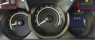
F12 (7.5 A) - right low beam, right headlight leveling motor. F13 (7.5 A) - left low beam, left headlight range control motor. If one of the low beam headlights does not light, check one of these fuses as well as the bulb itself. If both headlights do not work, check the serviceability of the light switch, its connector and the lamps themselves (it also happens that both burn out at the same time).
F14 (10 A) - right high beam, high beam warning light on the instrument panel. F15 (10 A) - left high beam lamp. If the high beams do not work, also check relay K7. If it fails, replace it. In addition, it could be in the lamps themselves, in the wiring, in the high beam switch and in its connector.
F16, 17 (10 A) - front fog lights.
F18 (15 A) - heated seats.
F19 (10A) - ABS. If the fuse is good, but the ABS does not work, then most likely one of its mechanisms has stopped working. If the ABS warning light on the instrument panel is on, one of its elements has failed. This is necessary to diagnose error codes and eliminate the cause.
F20 (15 A) - cigarette lighter. Frequent problems with the Kalina cigarette lighter can be caused by its non-standard configuration. When connecting various connectors, proper fastening does not occur, so short circuits may occur, as a result of which the fuse fails. Alternatively, you can install an additional connector or use a splitter with 12 V outlets.
F21 (10 A) - gearbox reverse lock.
F22 (15 A) - alarm control unit.
F23 - reserve F24 - reserve F25 - reserve
F26 (25A) - ABS. Same as F19.
F27 (5 A) - spare F28 (7.5 A) - spare F29 (10 A) - spare F30 (20 A) - spare
F31 (50 A) - electric power steering. If the steering wheel is tight, check this fuse and fuse F5. If the cause of the problem cannot be determined, contact a car repair shop, as steering is a serious safety issue. Maybe something with the control unit or wiring.
Adjusting the optics of Kalina in the hatchback body version
The main lighting equipment of this body type LADA Kalina has the same design as that of the sedan. These devices are distinguished by the fact that adjusting the headlights is simple and inexpensive. The corrective procedure is carried out to obtain optimal illumination of the front section of the road, while completely eliminating the risk of dazzling drivers of oncoming vehicles.
To conveniently carry out the adjustment process, the owner will need chalk and a tape measure. First of all, make sure that there is 50% fuel in the tank during adjustment. Mechanics recommend using an assistant who will be present in the driver's seat during the procedure. How to adjust headlights step by step:
- The car is placed on a similar flat area against the wall, on which the center of the car and the centers of the headlights are marked with chalk.
- Next, using a tape measure, measure a distance of 7.5 meters, at which we place a mark.
- It is at this moment that we are driving a LADA Kalina car.
- We connect the marked centers of the optical instruments with a straight line drawn with chalk. We also draw vertical lines through these centers.
- Next, we take 75 mm from the horizontally drawn line and draw a straight line parallel to it. For greater accuracy, we measure this distance in several places.
- We adjust the headlights while they are on and one at a time. When carrying out the process on the first optical device, cover the second with the indicated sheet of cardboard.
- The correct position of the reflector is obtained by turning the screws. Here it is necessary to obtain such a position of the light beam in which the vertex of the angle of the light point on the wall intersects a vertical line previously drawn through the central point of the projector.
The top edge of the beam section is aligned with the bottom line.
We perform similar manipulations for the second beacon.
Adjusting headlights on Kalina 2 and 1 begins with preparation. A beginner should study the manual or watch a video - this way it will be clear in what sequence to act, even if there is no knowledge, skills, or experience.
General scheme of actions:
- Align the body level, test the current tire pressure - the parameter must strictly meet the optimal criteria.
- Remove all dirt from the optics - oil, dust, and other substances. Typically, plain water is used; if this is not enough, you can use an organic-based solvent.
- Lubricate the adjustment screws with a penetrating liquid, treat the fasteners, and check the reliability of the optics in the niches specially designed for this.
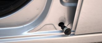
Step-by-step replacement instructions
Each H7 standard bulb has an iron base, which is pressed to the headlamp with a wire clamp. To bend this bracket, just get close to the plane of the headlight from behind. Let's open the hood and see what exactly will bother us.
Engine compartment of Kalina-2 (VAZ-2192, 2194)
Behind the headlight on the right is a washer reservoir. It is dismantled like this: disconnect the electric motor terminals, tighten the plug harder, find one nut and one fastening bolt. The fastening elements are unscrewed with a 10mm wrench, then the tank is placed on the engine. Next we could look at how to remove the headlight on Kalina-2, but in this case this is not required.
Before performing any manipulations with electrical equipment, always disconnect the negative terminal of the battery. It is better to connect this terminal last (before closing the hood). Be careful.
Replacement sequence:
- Remove the rubber cover covering the low beam lamp compartment;
- Disconnect both terminals from the lamp contacts;
- The fastening bracket is removed from the grooves by first pressing on it, then the bracket is moved to the side;
- They take out the lamp, install a new one in its place, and return the bracket to its place.