There are quite a few different types of mass air flow sensors: mechanical, ultrasonic, hot-wire and some others.
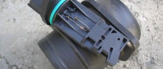
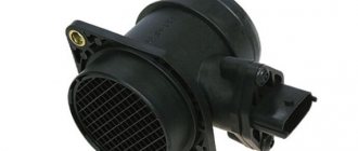
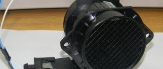
In this case, we will consider the design of the HFM-5 hot-wire sensor from Bosch, which is most often installed on VAZ cars. The sensor's sensitive element is a thin film on which several temperature sensors and a heating resistor are located. In the middle of the film there is a heating area, the degree of heating of which is controlled using a temperature sensor.
On the surface of the film, on the side of the air flow and on the opposite side, two more thermal sensors are located symmetrically, which record the same temperature in the absence of air flow. In the presence of air flow, the first sensor is cooled, and the temperature of the second remains unchanged, due to the heating of the air flow in the heater zone. The differential signal of both sensors is proportional to the mass of passing air.
- 1 – dielectric diaphragm
- H – heating resistor
- SH – Load temperature sensor. resistor
- SL – Air temperature sensor
- S1 and S2 – temperature sensors before and after the heater.
- QLM – air flow mass
- t – temperature
The sensor's electronic circuit converts this signal into a constant voltage proportional to the air mass. This design is called Hot Film (HFM), its advantages include high measurement accuracy and the ability to record reverse air flow, but its disadvantages include low reliability in conditions of contamination and moisture.
To measure the amount of air that enters the engine means to determine the engine load. When the driver presses the gas pedal, the throttle valve opens and the amount of intake air increases. At the same time, we say that the load has increased. When you release the pedal, the load drops. It's quite simple. However, this is only at first glance. If we take into account the fact that in real driving conditions the engine often changes operating modes and the incoming air in the intake system participates in several gas-dynamic processes, then the problem of measuring the air in the system is not so simple.
In older systems (ECU January-4 and GM-ISFI-2S), other hot-wire mass flow sensors were used, the sensitive elements of which were made in the form of threads. Such sensors are called Hot Wire MAF Sensor. The output signal of these sensors was frequency, that is, depending on the air flow, it was not the voltage that changed, but the frequency of the output pulses. The sensors were less accurate and did not allow registering reverse flow, but these shortcomings were offset by very high reliability.
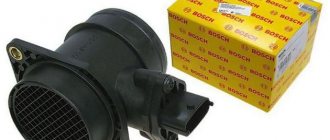
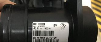
Several types of mass air flow sensors were installed on VAZ cars: GM, BOSCH, SIEMENS and Russian-made. In 1999-2004 Two types of sensors were installed on VAZ cars: 0 280 218-037 and 0 280 218-004. These sensors produce different output voltage (calibration) parameters at the same air flow rate and interchangeability (or rather, replacing 004 with 037) is only possible with the replacement of calibration tables in the firmware. The same applies to the new sensor 116, which has been installed as standard since the beginning of 2005.
The sensor is supplied only assembled, with a code and marked with a green circle.
On some classic cars, together with the January 7.2 ECU, Siemens-VDO sensors (5WK97014. AVTEL) were used:
They differ in calibration (from zero volts) and connection diagram.
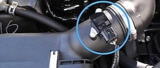
VAZ 2110 air sensor pinout diagram
- Yellow (closest to the windshield) - mass air flow sensor signal input;
- Gray-white—sensor supply voltage output;
- Green — sensor grounding output;
- Pink-black - to the main relay.
The wire colors may change, but the pin locations remain the same.
Let’s also add that the mass air flow sensor with endings 004, 037, 116 (for Bosch) and 00, 10, 20 (for Pekar) are different in calibration. You can only change it by flashing it.
Connecting the MAF air sensor VAZ 2112
If the mass air flow sensor is operational, then when the engine is running at 900 rpm, the volume of air used will be at least 10 kg per hour. When the speed increases to 2 thousand, this figure will increase to approximately 20 kg. If the volume of air at such speeds drops, the dynamics of the vehicle will also decrease, and accordingly, this will lead to a decrease in gasoline consumption.
If these indicators increase, this will also contribute to an increase in fuel volume. Deviations of the parameter by 2-3 kg should not be allowed, since in this case the operation of the power unit may be incorrect.
Useful: Connection diagram and pinout of the VAZ power window button
Interchangeability
This issue is quite relevant, especially taking into account the cost of original products from the imported automobile industry. But it’s not so simple here; let’s give an example. In the first production models of the Gorky Automobile Plant, the injection Volgas were equipped with a BOSCH air flow sensor. Somewhat later, imported sensors and controllers replaced domestic products.
A – imported filament air flow sensor manufactured by Bosh (pbt-gf30) and its domestic analogues B – JSCB “Impuls” and C – APZ
Structurally, these products were practically no different with the exception of several design features, namely:
All the sensors given as an example were interchangeable until the Gorky Automobile Plant switched to film analogues. The reasons for the transition were described above.
Film air flow sensor Siemens for GAZ 31105
It makes no sense to give a domestic analogue to the sensor shown in the figure, since outwardly it is practically no different.
It should be noted that when switching from filament devices to film devices, most likely, it will be necessary to change the entire system, namely: the sensor itself, the connecting wire from it to the ECU, and, in fact, the controller itself. In some cases, the control can be adapted (reflashed) to work with another sensor. This problem is due to the fact that most filament flowmeters send analog signals, while film flowmeters send digital signals.
It should be noted that the first production VAZ cars with an injection engine were equipped with a filament air flow sensor (made by GM) with a digital output; examples include models 2107, 2109, 2110, etc. Now they are equipped with air flow sensor BOSCH 0 280 218 004 .
To select analogues, you can use information from official sources or thematic forums. As an example, below is a table of the interchangeability of mass air flow sensors for VAZ cars.
Compatibility table for mass air flow sensor for the VAZ model range
The presented table clearly shows that, for example, the MAF sensor 0-280-218-116 is compatible with VAZ 21124 and 21214 engines, but is not suitable for 2114, 2112 (including those with 16 valves). Accordingly, you can find information on other VAZ models (for example, Lada Granta, Kalina, Priora, 21099, 2115, Chevrolet Niva, etc.).
As a rule, there will be no problems with other brands of cars of domestic or joint production (UAZ Patriot ZMZ 409, Daewoo Lanos or Nexia), choosing a replacement mass air flow sensor for them will not be a problem, the same applies to products of the Chinese automobile industry (KIA Ceed, Spectra, Sportage etc.). But in this case, there is a high probability that the MAF pinout may not match; a soldering iron will help correct the situation.
The situation is much more complicated with European, American and Japanese cars. Therefore, if you have a Toyota, Volkswagen Passat, Subaru, Mercedes, Ford Focus, Nissan Premiere P12, Renault Megane or another European, American or Japanese car, before replacing the mass air flow sensor, you need to carefully weigh all the solution options.
If you are interested, you can search online for an epic about an attempt to replace the “native” air meter with an analogue on a Nissan Almera H16. One attempt resulted in excessive fuel consumption even at idle.
In some cases, searching for an analogue one will be justified, especially if you take into account the cost of the “native” VU meter (for example, the BMW E160 or Nissan X-Trail T30).
Connection diagram for air flow sensor 2114
A common cause of incorrect operation of the mass air flow sensor is the failure of electronic components, which increases the sensor’s response time to changes in air flow. A working sensor monitors changes at a speed of 0.5 ms, and if it breaks down, the response time increases by 20-30 times. The defect is detected only by recording the operation graph with an oscilloscope. Such a sensor cannot be repaired; it must be replaced with a new one.
Diagnosis of device malfunctions
Determining a problem with the mass air flow sensor is not so easy. Many symptoms of failure of this sensor coincide with signs of failure of other components and assemblies of the car. Typical symptoms of problems with the mass air flow sensor are cases when:
- the engine noticeably loses power;
- there are failures when pressing the accelerator;
- fuel consumption increases significantly;
- Starting a warm engine becomes more difficult.
When the mass air flow sensor fails, the Check Engine light on the dashboard lights up. But it turns on not only when the mass air flow sensor fails. And it’s not at all easy to figure out what kind of breakdown the indicator is signaling in this case, so it’s better to turn to professionals for diagnostics.
Cases when the average car enthusiast can figure it out on his own are relatively rare. These include a situation when you suspect a failure of the mass air flow sensor, and your friend has the same “nine” as yours with a perfectly working engine. Borrow a known-good air flow sensor from a friend for one hour. Remove your sensor, install a good one, and go for a ride. If the problems disappear, go to the store for a flow meter: the problem is that the mass air flow sensor is broken.
Checking the air sensor yourself
When a malfunction of the mass air flow sensor occurs, the air-fuel mixture becomes over-rich or lean, which immediately affects the operation of the engine and may ultimately result in engine failure.
Symptoms of a malfunctioning mass air flow sensor:
- Check Engine error appears;
- Increased fuel consumption;
- Doesn't start well when hot;
- The car began to accelerate slowly;
- Engine power lost.
The easiest way to check the mass air flow sensor on a VAZ 2114 is to disconnect the plug. If there is no signal, the engine control unit goes into emergency operation mode, determining the approximate air volume based on the throttle position. At the same time, fuel consumption increases slightly - for the VAZ 2114 it reaches 10-12 liters per 100 km. A characteristic feature is the increase in idle speed to 1500 rpm. But when using a January 7.2 or Bosch M7.9.7 controller, the idle speed does not increase due to the software features.
The normal voltage at the output of the new sensor is 0.996 - 1.01 Volts. During operation, it gradually changes and, as a rule, increases. The greater the value of this voltage, the greater the wear of the mass air flow sensor.
Here is the reference voltage in volts:
- 1.01 – 1.02 – good condition of the sensor.
- 1.02 – 1.03 – not a bad condition.
- 1.03 – 1.04 - the life of the mass air flow sensor is coming to an end.
- 1.04 – 1.05 — emergency condition.
- 1.05 and above - it’s time to replace the mass air flow sensor.
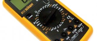
The measurement is made between the yellow and green wires. Voltage values can be displayed on the screen of some on-board computers (menu voltage from sensors, U Mass air flow sensor).
Important: the limits and fluctuations of the output voltage in at least 30% of cases for a faulty sensor will be NORMAL and will not cause the “Check” icon on the panel. That is, voltage measurements are uninformative, but the rate that it will produce in kilograms of air will correspond to the movement not where it actually is, and the ECU will interfere with the mixture based on it - hence the extra consumption!
You need to check the sensor at a service center, preferably with a proprietary scanner, which itself indicates by blinking if there is a imbalance in some parameter (in this case, air flow in kilograms), comparing it with the reference values stored in its memory.
Main symptoms
So. If you have problems with your mass air flow sensor, the signs of a malfunction can be very different. Among them are failures during acceleration, lack of traction, and decreased power. There is a persistent feeling that the car simply “does not go.” If there is no proper response when you press the gas, then this is one of the signs. High fuel consumption is also a signal for diagnosing this sensor. When your car stalls when shifting from gear to gear, it makes sense to check the MAF sensor. The VAZ 2110 has the same symptoms of malfunction as other cars.
Replacing the sensor - instructions
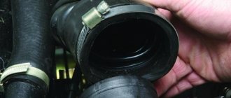
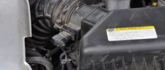
Using a screwdriver, unscrew the clamp of the air intake corrugation at the sensor outlet, pull it off and carefully inspect the internal surfaces of the sensor itself and the corrugation. These surfaces must be dry and clean; traces of condensation and oil are unacceptable. If the air filter is changed rarely, then dirt getting on the sensitive element of the sensor is the most common cause of its breakdown in VAZ cars.
There may be oil in the mass air flow sensor as a result of an increased oil level in the engine crankcase, or the oil sump of the crankcase ventilation system is clogged.
Next, unscrew the 2 screws of the sensor with a 10mm wrench and remove it from the air filter housing. There should be a rubber sealing ring on its front part (at the entrance edge). It prevents unfiltered air from being sucked into the intake tract through the sensor.
If the ring is out of place and stuck somewhere in the air filter housing, then there will be a thin layer of dust on the inlet mesh of the sensor itself. This is the second reason that destroys the mass air flow sensor ahead of time.
Correct assembly should take place in the following sequence: put a sealing rubber band on the sensor, check the sealing skirt, then insert everything together into the filter housing.
This concludes the visual check of the mass air flow sensor at home. You can check its operation 100% only with the help of special equipment in a car service center. For example, using a technique for assessing the oscillogram when the throttle is sharply opened to the cutoff mode (a motor tester is needed), or assessing the oscillogram when the ignition is turned on.
Resuscitation of a damaged air flow sensor is successful in no more than 5% of cases. In extreme cases, you can rinse with ethereal liquid to clean matrices and optics. It will evaporate without a trace. After making sure that there is no more dust or debris in the device, you can dry it thoroughly and put it back in place. Sometimes after such a simple procedure the device will work.
On most foreign cars, a mass air flow sensor was installed until 2000; subsequent generations of models began to be equipped with a pressure controller. Replacing a non-working sensor is simple and can be done on your own without any problems, you just need to buy a mass air flow sensor that matches the ECU firmware version. Its price is around 3,000 rubles, depending on the manufacturer.
Types of mass air flow sensors, their design features and operating principle
Three types of VU meters are most widespread:
In the first two, the operating principle is based on obtaining information about the mass of the air flow by measuring its temperature. The latter may involve two accounting options:
Vortex sensor design (widely used by Mitsubishi Motors)
Designations:
Wire sensors
Until recently, thread mass air flow sensor was the most common type of sensor installed on domestic cars of the GAZ and VAZ model range. An example of a wire flow meter design is shown below.
Design of volumetric meter IVKSH 407282.000
Designations:
Operating principle and example of a functional diagram of a filament VU meter.
Having understood the design of the device, let's move on to the principle of its operation, it is based on the hot-wire method, in which a thermistor (RT), heated by the current passing through it, is placed in the air flow. Under its influence, the heat transfer changes, and, accordingly, the resistance RT, which makes it possible to calculate the volumetric flow rate of the air mixture? using King's equation:
where I is the current passing through RT and heating it to temperature T1. In this case, T2 is the ambient temperature, and K1 and K2 are constant coefficients.
Based on the above formula, you can derive the volumetric air flow rate:
An example of a functional diagram with bridge connection of thermoelements is shown below.
Typical functional diagram of a wire mass air flow sensor
Designations:
When the flow velocity is close to zero, the RT is heated to a certain temperature by the current passing through it, which allows the bridge to be kept in equilibrium. As soon as the flow of the air mixture increases, the thermistor begins to cool, which leads to a change in its internal resistance, and, as a result, an imbalance in the bridge circuit. As a result of this process, a current is generated at the output of the amplifier unit, which partially passes through the temperature compensator, which leads to the release of heat and makes it possible to compensate for its loss from the flow of the air mixture and restores the balance of the bridge.
The described process allows you to calculate the flow rate of the air mixture based on the amount of current passing through the bridge. In order for the signal to be perceived by the ECU, it is converted into a digital or analog format. The first allows you to determine the flow rate by the frequency of the output voltage, the second - by its level.
This implementation has a significant drawback - a high temperature error, so many manufacturers add a thermistor similar to the main one to the design, but do not expose it to air flow.
During operation, dust or dirt deposits may accumulate on the wire thermistor; to prevent this, this element is subjected to short-term high-temperature heating. It is performed after the internal combustion engine is turned off.
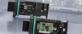
Film air meters
A film MAF works on the same principle as a filament one. The main differences lie in the design. In particular, silicon crystal is used instead of platinum filament resistance wire. It is coated with several layers of platinum plating, each of which plays a specific functional role, namely:
This crystal is installed in a protective casing and placed in a special channel through which the air mixture passes. The geometry of the channel is designed in such a way that temperature measurements are taken not only from the input flow, but also from the reflected flow. Thanks to the created conditions, a high speed of movement of the air mixture is achieved, which does not contribute to the deposition of dust or dirt on the protective housing of the crystal.