tinki-vinki › Blog › Checking the mass air flow sensor of the VAZ 2110
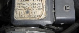
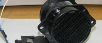
The mass air flow sensor (MAF)
is a device designed to estimate the amount of air entering the car engine. It is one of the sensors of electronic engine management systems of vehicles with fuel injection.
The mass air flow sensor can be used in conjunction with air temperature and atmospheric pressure sensors, which correct its readings. Malfunctions of the mass air flow sensor negatively affect engine performance. Don’t rush to replace it with a new one, try checking the mass air flow sensor first.
Symptoms of a malfunctioning mass air flow sensor:
• Check Engine error appears; • Increased fuel consumption; • Poor starting when hot; • The car began to accelerate slowly; • Engine power lost.
How to check the mass air flow sensor:
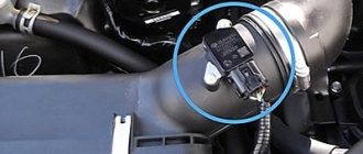
Method number 1: Disable mass air flow sensor
Disconnect the sensor connector and start the engine. If you turn off the mass air flow sensor, the controller switches to emergency mode and prepares the fuel mixture only based on the throttle position. Engine speed must be greater than 1500 rpm. Let's try to go for a ride. If the car feels “faster”, then we can say that the mass air flow sensor is not working. By the way, for ECU Y7.2, M7.9.7. The speed does not increase when the chip is turned off!
Method No. 2: Alternative ECU firmware
If the standard firmware of the controller was replaced with another, then it is unknown what is built into it in case of emergency mode in method No. 1. Try sliding a 1 mm thick plate under the damper stop. The revs will rise. Pull out the chip from the mass air flow sensor. If it doesn’t stall, it means the problem is with the firmware, or rather with the IAC steps in emergency mode without a mass air flow sensor.
Method No. 3: Checking the mass air flow sensor with a multimeter
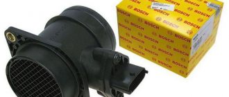
This method works on Bosch sensors with catalog numbers: 0 280 218 004, 0 280 218 037, 0 280 218 116. Turn on the tester in DC voltage measurement mode, set the measurement limit to 2 volts.
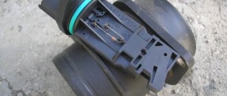
1. Yellow (closest to the windshield) - mass air flow sensor signal input; 2. Gray-white - sensor supply voltage output; 3. Green - sensor grounding output; 4. Pink-black - to the main relay;
The wire colors may change, but the pin locations remain the same.
We turn on the ignition, but do not start the engine. We connect the multimeter with the red probe to the yellow mass flow sensor, and the black one to the green one (to ground). Thus, we measure the voltage between the specified terminals. The tester probes allow you to penetrate through the rubber seals of the connector, along the specified wires, without disturbing their insulation. The use of needles and other additional connections is not recommended, because they introduce some error into measurements. We take readings from the multimeter. The output voltage of the new sensor is 0.996…1.01 Volts. During operation, it gradually changes and, as a rule, increases. The greater the value of this voltage, the greater the wear of the mass air flow sensor.
Mass air flow sensor voltage:
• 1.01...1.02 - good condition of the sensor • 1.02...1.03 - not a bad condition • 1.03...1.04 - the service life of the mass air flow sensor is coming to an end • 1.04...1.05 - a dying state, if there are no negative symptoms, then we continue to use it • 1.05...and above - it’s time to replace Mass air flow sensor
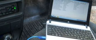
By the way, the same readings can be obtained without a tester, using the on-board computer (group of parameters “voltage from sensors”, Udmrv)
Method No. 4: Visual inspection of the mass air flow sensor
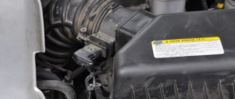
Using a figured screwdriver, unscrew the clamp of the air intake corrugation at the sensor outlet, pull it off, and carefully inspect the internal surfaces of the sensor itself and the corrugation. These surfaces must be dry and clean; traces of condensation and oil are unacceptable. If the air filter is changed rarely, then dirt getting on the sensitive element of the sensor is the most common cause of its failure. There may be oil in the mass air flow sensor as a result of an increased oil level in the engine crankcase, or the oil bumper of the crankcase ventilation system is clogged.
Unscrew the 2 screws of the sensor (using a 10mm wrench) and remove it from the air filter housing. There should be a rubber sealing ring on its front part (at the entrance edge). It prevents unfiltered air from being sucked into the intake tract through the sensor. If the ring is out of place and stuck somewhere in the air filter housing, then there will be a thin layer of dust on the inlet mesh of the sensor itself. This is the second reason that destroys the mass air flow sensor ahead of time. Correct assembly should take place in the following sequence: put a sealing rubber band on the sensor, check the sealing skirt, then insert everything together into the filter housing.
Replacement of the MAF sensor is in the service manual. This concludes checking the mass air flow sensor at home. Its operation can only be checked 100% using special equipment. For example, using a technique for assessing the oscillogram when the throttle is sharply opened to the cutoff mode (a motor tester is needed), or assessing the oscillogram when the ignition is turned on, etc.
There is another unique method - the fastest and best diagnostics of the mass air flow sensor - the help of a friend who can borrow his working mass air flow sensor for a while. If after installing it you feel a noticeable difference, then the mass air flow sensor needs to be changed! Is the mass air flow sensor faulty? Try cleaning it. If this does not help, then you should buy a new sensor. By the way, high fuel consumption can be the cause of other vehicle malfunctions.
Comment, like, subscribe. Thanks to all