Most vehicle electrical circuits are protected by fuses.
Electric motors of gear motors (windshield wipers, tailgate glass, headlights - if installed) are protected by automatic reusable bimetallic fuses.
The power supply circuit of the injection system (VAZ-21214 engine) is protected by a fuse-link made of wire with a conductor of reduced cross-section (1 mm 2 ).
The battery charging, ignition (VAZ-21213 engine), engine starting, and the “generator – ignition switch – fuse box” circuits are not protected.
Powerful consumers (starter, headlights, electric motors for cooling system fans, electric fuel pump, etc.) are connected via a relay.
The fuses are grouped in two fuse blocks located on the left under the instrument panel.
The fuse ratings and the circuits they protect are shown in the table.
The injection system fuses (VAZ-21214 engine) are located in a separate block on the left side panel under the instrument panel.
A 30 A fuse protects the power supply circuit for the electric radiator fans, and three 15 A fuses protect the electric fuel pump, the control unit (constant power input) and the injection system main relay circuits, respectively.
Reasons for refusal
As a rule, frequent relay failure is due to the poor quality of components, both those supplied from the factory and those still alive "cooperatives". Combating this can only be done by cautiously approaching the selection or having a few other spare parts. Repairs on a dime are not recommended, although there are examples of restorations “just for fun.” The only difficulty is accessing the place where the relay turns the Niva, change it. it's 2 minutes.
Another reason that can kill the switch is increased voltage in the on-board network as a result of failure of the generator components and the voltage regulator relay. Closing is also possible. In any case, the chain is scanned, starting with a simple one. fuse condition .
symptoms
The symptomatology of the malfunction has its own characteristics and differs from the burning of an incandescent lamp or damage to the circuit. Thus, if the problem is in the relay, then when turning the switch the driver will see one of the following manifestations:
- The indicator does not light up, the turn signals are off;
- The dashboard indicator and turn signals are constantly on;
- When the relay operates, an uncharacteristic crack (clicks) occurs;
- Within a short time there is a change in the pace of functioning;
- Different response rate compared to alarm.
Failure of the rectifier unit (diode bridge burnt out)
This is the most common reason why there may be either weak charging or its complete absence. In order to find out whether this is the reason, you must perform the following steps:
- Remove the diode bridge from the device
- Test it with an ohmmeter to check for burnt diodes.
- Replace the rectifier unit if necessary
Usually, if one of the diodes burns out, the charging does not disappear completely, but becomes only slightly less than the nominal value. But even in this case, the generator will not be able to properly charge the battery and it will run out more and more often. If all the diodes burn out, which also happens quite often, then charging disappears completely.
Replacement method
For operations you need:
- Key head to “10” (preferably with a ratchet mechanism);
- Plastic puller or similar device;
- Pliers;
- Phillips screwdriver.
- 1. Take a screwdriver and loosen the instrument panel from the two self-tapping screws.
2. Carefully apply the shield to yourself, overcoming the resistance of the pair of latches at the top of the part.
3. Unscrew the dashboard using the “10” key.
4. Slowly dismantle the instrument cluster, while at the same time getting rid of the union nut of the flexible speedometer drive shaft using pliers.
5. Disconnect the wires by removing the two gaskets.
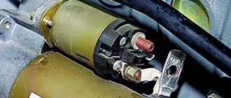
After establishing the place where the relay turns to the Niva, unscrew the nut to “10”, by the way, disconnect the 3 wires from the “ground” from the stud. Pull the device towards you and then, using a slight swing, pull the shoe out. Replace the switch with a new one as shown in the photo .
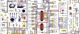
Electrical diagram of VAZ-21213
1. Front lights.2. Side direction indicators.3. Windshield washer motor.4. Headlight washer motor*.5. Switch.6. Rechargeable battery.7. Starter VAZ-21213.8. Generator.9. Headlights.10. Geared motors for headlight cleaners*.11. Sound signal.12. Spark plugs.13. Carburetor limit switch.14. Carburetor solenoid valve.15. Ignition coil.16. Windshield wiper motor gearbox.17. Carburetor solenoid valve control unit.18. Ignition distributor sensor.19. Coolant temperature indicator sensor.20. Insufficient oil pressure indicator sensor.21. Portable lamp socket**.22. Insufficient brake fluid level indicator sensor.23. Windshield wiper relay-breaker.24. Relay for turning on rear fog light lamps***.25. Relay for turning on the rear window heating element.26. Relay for turning on the headlight cleaners and washer*.27. Relay for turning on low beam headlights.28. Headlight high beam relay.30. Starter activation relay.31. Relay-breaker for hazard warning lights and direction indicators.32. Heater electric motor.33. Additional resistor for heater electric motor.34. Illumination lamps for heater control levers.35. External lighting lamp switch.36. Main fuse block.37. Additional fuse block.38. Reversing light switch.39. Brake light switch.40. Regulator for instrument lighting lamps.41. Ignition switch.42. Three-lever switch.43. Hazard switch.44. Switch for headlight cleaners and washers.45. Heater motor switch.46. Rear window heating element switch.47. Rear fog light switch.48. Lamp switches located in the door pillars.49. Interior lighting lamps.50. Cigarette lighter VAZ-21213.51. Switch for the carburetor choke indicator lamp.52. Indicator lamp for closing the carburetor air damper.53. Switch for the differential lock indicator lamp.54. Parking brake indicator lamp switch.55. Level indicator and fuel reserve sensor.56. Instrument cluster.57. Rear window washer motor.58. Tail lights.59. Block for connecting additional brake lights.60. Blocks for connecting side marker indicators.61. Pads for connecting to the rear window heating element.62. License plate lights.63. Rear window wiper motor.
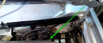
Location of the relay and fuse box
Setting up a windshield wiper for a Niva VAZ-21213 car
Fuses and relays are located on one block in a Chevrolet Niva car. Many owners of a Chevrolet Niva SUV, when a malfunction occurs in one or another electrical unit, ask the question: “Where are the fuses in a Chevrolet Niva car?” You need to look for it in the cabin, under the dashboard. To be more precise, it is located on the driver’s seat side. But in order to get to it, you need to open the cover under the panel, which is screwed in with two self-tapping screws.
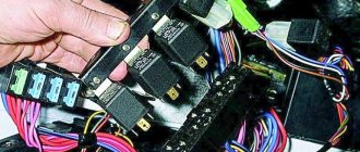
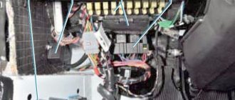
By unscrewing them and removing the cover, you can see our actual relay unit with protective products. It is a plastic base on which our switching and protective devices are located. Now an even more important question arises: “What is each of these devices responsible for?” To do this, you need to consider the block and describe the purpose of each of them, which is what we will do.
Block diagram and relay description
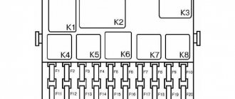
To be able to visually examine, we use a diagram of a 2010 Chevrolet Niva car, which looks like:
Read
The diagram is presented in expanded form, in reality it is installed in the reverse position, so when removing parts, do not forget about this. Each product is numbered in the diagram, so let's start with the relay
- K1 The main relay, which is responsible for the operating status of the car lamps.
- K2 Switching element that controls the operation of a car mechanism such as wipers.
- K3 Intermittent relay, through which the turns and emergency lights operate. When you turn on the emergency lights or turn, characteristic clicks are heard in the cabin. This is our relay clicking.
- K4 Switching device for current supplying low beam
. - K5 Same as K4, only for high beam.
- K6 Supplement relay. This is not a spare product, it is responsible for the operation of the car's ignition.
- K7 Current switching relay, which is responsible for the operation of the rear window heater.
- K8 Is a spare or backup device.
There are many more fuses in a Niva Chevrolet car, so it’s worth paying special attention to each
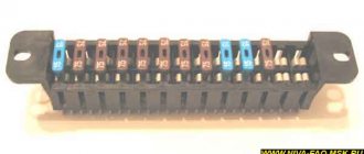
Protective elements
Actually, such an element is called contact with a fuse-link, which performs a protective function. When a current passes through the circuit above the permissible limit, the insert burns out, thereby protecting the main part from burnout.
This type of mounting block is also possible
Read
The block consists of 20 fuses that are responsible for certain devices. Let’s take a closer look at what these devices are:
- F1 is responsible for the operation of the following lighting lamps in the car design: left side lights, dashboard lights, license plates, warning lamp on the dashboard, engine compartment lighting and an additional STOP signal.
- F2 determines the protection of the left low beam lamp.
- F3 too, only for high beam. Illumination on the dashboard.
- F4 spare element or reserve place.
- F5 is a device that protects the power supply circuit of the front door windows of the Chevrolet Niva.
- F6 protection of the control circuit of the door lock block. If it is impossible to open the doors using the remote control, it is worth checking this element.
- F7 protection of the horn and cigarette lighter circuit. The cigarette lighter consumes a lot of current, so it is necessary to install a product with a fuse link of 20A or no less.
- F8 rear window defroster.
- F9 element, which is responsible for protecting the power circuit of the following devices:
- rear window wiper motor;
- glass cleaner/washer switch;
- additional relay.
- F10 reserve
- F11 protective element for right-hand side lamps.
- F12 is responsible for the serviceability of the low beam in the right headlight. It also protects the power supply circuit of the gearmotor of the hydraulic headlight correctors.
- F13- determines the protection of the power supply circuit of the high beam lamp in the right headlight.
- F14 and F15 are backup products, which are designed for switching circuits with currents of no more than 10 and 20 A, respectively.
- F16 is a fuse responsible for the serviceability of the hazard warning lights and turn signals.
The second version of the NIVA 21213 scheme
1. Headlights 2. Headlights 3. Headlight wiper motors 4. Horn 5. Headlight washer motor 6. Windshield washer motor 7. Generator 8. Side turn signals 9. Battery 10. Heater motor 11. Additional heater motor resistor 12 Windshield wiper breaker relay 13. Starter 14. Windshield wiper motor 15. Carburetor limit switch 16. Carburetor solenoid valve 17. Carburetor solenoid valve control unit 18. Switch 19. Spark plugs 20. Ignition distributor sensor 21. Control sensor oil pressure lamps 22. Temperature indicator sensor 23. Socket for a portable lamp 24. Ignition coil 25. Brake fluid level warning lamp sensor 26. Relay for turning on the headlight cleaners and washer 27. Relay for turning on the heated rear window 28. Relay for turning on the high beam headlights 29 . Headlight low beam relay 30. Ignition on relay 31. Starter on relay 32. Differential lock warning lamp switch 33. Exterior lighting switch 34. Cigarette lighter 35. Brake light switch 36. Reverse light switch 37. Turn signal breaker relay and alarm 38. Main fuse block 39. Additional fuse block 40. Illumination lamps for heater control levers, 41. Rear fog light switch 42. Rear window heating switch 43. Heater motor switch 44. Rear window wiper and washer switch 45. Emergency switch alarm 46. Ignition switch 47. Carburetor choke warning lamp 48. Instrument lighting switch 49. Steering column three-lever switch 50. Carburetor choke warning lamp switch 51. Rear window washer motor 52. Courtesy lamp switches located in the door pillars 53. Interior lamps 54. Instrument cluster 55. License plate lights 56. Parking brake warning lamp switch 57. Level indicator and fuel reserve sensor 58. Tail lights 59. Rear window wiper motor 60. Rear window heating element 21213.
Fuses Niva 21214 injector - Selection Auto 163
Any car is equipped with fuse blocks (FBs), which are responsible for the safety of electrical circuits. Their location differs not only depending on the make of the car. Even models from the same manufacturer that are close in year of production can be placed in different patterns. However, in some cases the location may coincide completely.
Where are the blocks and relays located in Niva 21214 and 21213
The main power supply in these models is located under the lower edge of the instrument panel protection. Additional fuses in Niva 21214 for the injector are located to the left. This block is responsible for controlling fuel injection. There are also relays for monitoring the operation of the wipers and a set responsible for the motion control system.
Another fuse box is installed in the body to the left of the main one. They are responsible for the cooling system and how the engine works. There is also a diagnostic connector. The relay that controls the starter is located either next to the main power supply, or under the hood next to the brake fluid reservoir.
Designations of fuses and their purpose
Each of the fuses (FC) is responsible for a separate element of the vehicle's electrical circuit. In the main block, the numbering goes from left to right. There are 16 elements in total: 10 in the top row and 6 in the bottom.
Description of the upper section:
- Rear wiper motor, fluid supply to the front window, heater fan motor.
- Turn signals, reverse indicator, switches under the steering wheel, instrument panel and indicator lights.
- High beam (left headlight), indicator on the dashboard for turning on the high beam.
- High beam (right headlight).
- Low beam (left headlight).
- Low beam (right headlight).
- Dimensions (left side), license plate lighting, indicators on the instrument panel for turning on the dimensions.
- Dimensions (right side), instrument panel lighting.
- Hazard signal relay and power button, heated rear window.
- Brake lights, interior lighting, horn.
All fuses except the first have a rated current of 8A (PR1 - 16A). The bottom row is responsible for the following:
- Storage of 8A inserts
- Similar to the previous one.
- Rear fog lights.
- Cigarette lighter.
- Storage of 16A insert.
- Same for 8A.
The next power supply is responsible for the operation of the engine. The fuse diagram for Niva 21213 assumes 5 positions, and VAZ 21214 with an installed ABS system - 7 (positions 5-7 are responsible for it). The circuit without ABS looks like this:
- Start the electric fan motor on the right (30A).
- A similar position for the left side.
- Injection system control, injection nozzles, ignition coil, fan relay (15A).
- System for reducing the toxic component of gases, sensor of air supplied to the internal combustion engine (15A).
- Connector for diagnosing the operation of the injection system.
Relay blocks
The location of these blocks should be clarified according to the vehicle documentation. Also, some car enthusiasts sometimes tolerate them. Therefore, when buying a used car, it is better to check about possible changes. Engine control system unit from left to right:
- Ignition.
- Engine starting system.
- Right radiator fan.
- Similar left fan.
- Fuel pump operation.
- PR power supply for the fuel pump (15A).
The last key relay block, located above the gas pedal, is responsible for the lighting and heated rear window.
Useful video
When replacing the entire unit, it is important to write down the location and markings of the wires on the old one. The fuses themselves can be changed without any problems.
The main thing is to remove the terminals from the battery to avoid electric shock.
It is important to pay attention - if a new fuse burns out immediately after installation and performance testing, then the wiring of a specific circuit is damaged
- Chevrolet Niva
- Chevrolet Niva wiring diagram: Main sources of energy consumption
Article rating:
Loading…
Share with friends:
Related publications
carcheck163.ru
Additional schemes
Diagram for switching on direction indicators and hazard warning lights
1 — direction indicator lamps in the front lights; 2 — side direction indicators; 3 — ignition switch; 4 - ignition relay; 5 — fuse block VAZ-21213; 6 — direction indicator lamps in the rear lights; 7 - control pump for direction indicators in the instrument cluster; 8 — relay-switch for direction indicators and hazard warning lights; 9 — alarm switch; 10 — direction indicator switch.
External lighting switching diagram
1 — side light lamps in the front lights; 2 - fuse block; 3 — external lighting switch; 4 — instrument lighting switch; 5 - indicator lamp for external lighting in the instrument cluster; 6 — license plate lights; 7 — side light lamps in the rear lights; A - to the lighting lamps of the instrument cluster, switches and backlight display of the VAZ-21213.
Connection diagram for carburetor solenoid valve control system
1 — ignition switch VAZ-21213; 2 - ignition relay; 3 - ignition coil; 4 — control unit; 5 - solenoid valve; 6 — carburetor limit switch.
Removal of the turn signal and hazard warning relay on a VAZ 2121 and Niva 2131 is carried out in order to replace it in case of failure, as well as if its presence will interfere with the progress of other work. Prepare a standard set of tools and perform the following sequence of actions:
- First of all, you need to turn off the power to the car; to do this, unscrew the minus terminal from the battery.
- To make it easier to remove the relay, it is necessary to dismantle the instrument cluster.
- Using a ten-point socket, unscrew the nut securing the relay to the body stud, remove the nut and the ground wire tips located under it.
- We remove the relay and disconnect the block with the supply wires from it.
At this point, the repair work on removing the turn signal and hazard warning relays on the VAZ 2121 and Niva 2131 has been completed. Make the necessary repairs, then install in the reverse order.
Mounting blocks for Lada 4×4 2018
Generator Niva 21213, connection diagram
Main and additional units located in the cabin to the left of the steering wheel, under the instrument panel. The blocks contain fuses of the “Cylinder” size, ten and six fuses, respectively. The ratings and purpose of the fuses are indicated in Table 4 “Circuits protected by fuses”:
Fuse block of standard size “Standard”. The block is located on the left side under the upholstery and contains fuses that are designed to protect engine control system devices. The ratings and purpose of the fuses are shown in Table 5:
The fuse and relay box is located on the left side of the steering column under the instrument panel. The block contains two “Standard” size fuses, which are designed to protect the circuits of the electric fuel pump, electric windows and electric mirrors. The ratings and purpose of the fuses are shown in Table 6:
The fuse and relay box is located on the right side of the steering column under the instrument panel. The block contains one “Maxi” size fuse and two “Standard” size fuses, which are designed to protect the circuits of the hydraulic unit of the anti-lock braking system. The ratings and purpose of the fuses are shown in Table 7:
Attention! The relay and fuse diagram may differ depending on the configuration and production date of the vehicle. Current diagrams of the mounting block are presented in the operating manual for the date of manufacture of the vehicle (download from
site for 3dv. or 5door).
Why does a fuse or light relay or any other constantly blow out? Before replacing it with a similar one, you must first find and eliminate the cause of its burnout. This could be a short circuit, incorrectly selected rated current, etc. Use electrical circuit diagrams to troubleshoot problems. Questions on this topic can be asked on the forum.