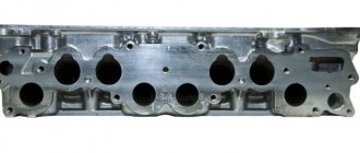
The transition from adjusting bolts to hydraulic compensators (HC) made it possible to abandon the need to adjust thermal clearances every 10 thousand kilometers. The operating principle of hydraulic compensators, as well as their diagnostics, are described in the article Why hydraulic compensators knock when hot and cold. In this article we will talk about how to change hydraulic compensators on a Chevrolet Niva with your own hands. Such a replacement is necessary if the problem is not in the oil system or inappropriate engine oil, but in the malfunction of these parts. Niva Chevrolet hydraulic compensators often cause trouble for car owners - valves knock, the engine begins to work intermittently.
Preparing the car for replacement.
Replacing hydraulic compensators on a Chevrolet Niva with your own hands does not take very much time, and the work will require a minimum set of tools and skills.
- The car is placed on any flat surface, after which the gearbox is switched to neutral and the handbrake is applied.
- Open the hood and disconnect the air duct
- Remove the clamps and pipes from the valve cover
- Unscrew the bolts that hold the valve cover
What it is?
This element is a piston with the help of which automatic operation occurs. The operating principle of this device is quite simple. The bottom of the piston interacts with the camshaft cam.
A ball valve is installed in the piston, with the help of which the valve opens and oil flow begins. As the piston is filled with oil, pressure will be applied to the existing plunger, causing the piston to move all the way to the cam. As a result, the most optimal gap is automatically installed. When the cam acts on the piston, some of the oil escapes through the valve.
The piston drops slightly, thereby creating a gap. The latter on the hydraulic compressor is regulated by the flow of incoming oil. At this stage, we learned what hydraulic compensators (their devices) are.
Replacement
- We set the marks on the camshaft so that they coincide with the back of the gear.
- We loosen the star bolt so that its tensioner can be removed.
- To facilitate further work, it is necessary to recess the tensioner into the plunger, then secure it with a special nut with a cap.
- We unscrew the nuts that secure the camshaft and remove it.
- We take out 8 rockers, after which we can begin dismantling the expansion joints.
- Carefully remove the parts and place them in a specially prepared container.
After this, you can proceed to installing new parts.
New parts are installed using a special torque wrench with a force of 2 kgf. This is necessary so as not to overtighten it and leave it loose. After this, we install the rockers in place and reassemble in the reverse order. An important point during assembly is the installation of the sprocket and chain tensioner.
Before tightening the chain, you must set all the marks correctly, then you can fix it with a tension nut. After this, you can install the valve cover in place and attach the clamps and pipes. After assembly, you need to start the engine to check the installation result. At first, the knocking sound may persist because it takes time for the hydraulic compensators to fill with oil, after which their operation should stabilize.
At this point, the replacement of hydraulic compensators on the Chevrolet Niva is considered complete.
It is worth remembering that replacing hydraulic compensators is not always necessary. Sometimes the cause of knocking can be old engine oil that has changed viscosity. To avoid this, it is necessary to change the engine oil on time. According to the manufacturer's recommendations, it should be done every 7-10 thousand kilometers. In this case, it is necessary to use oil with a suitable viscosity index. For summer it is better to choose brands with parameters 10W40, and for winter 0W30 or 5W30.
Final Installation Process
After this, apply a thin layer of sealant to the clean, grease-free surface of the lid at the point of contact with the metal. This must be done carefully and evenly distribute the sealing material squeezed out of the tube. Now let's put the gasket in place. All these actions must be done with pinpoint precision, making sure that nothing is warped and the gasket does not stick out.
Now all that remains is to tighten the lock correctly. Under no circumstances should you tighten one side first and then the other, as the gasket will still be skewed and pressed to the side. It is necessary to screw it diagonally, gradually tightening it to the end.
The device of hydraulic compensators.
Previously, rockers were used to adjust valves on VAZ engines, and the clearances were adjusted using special screws. On new engines, compensators are installed that look like adjustment bolts, but the clearances are adjusted automatically due to the plunger pair and oil pressure.
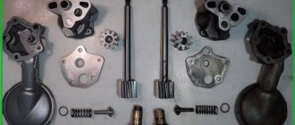
The hydraulic compensator consists of:
- Housings
- Return spring
- Top and bottom of plunger and check valve.
Despite a number of advantages, such a mechanism also has disadvantages that appear when the following reasons arise:
- insufficient oil pressure
- contaminated oil channels
- low oil level
- wear of parts.
Therefore, when the engine is cold started, the parts begin to knock, then when the operating temperature is reached, the gaps decrease and the sound disappears. If adding new oil does not solve the problem, then the Niva Chevrolet hydraulic compressors need to be replaced.
If repairs are not carried out in a timely manner, more serious problems may arise that will lead to wear on the camshaft lobes, rockers and valve stems. It is not recommended to continue operating a vehicle with such malfunctions, as this will increase fuel consumption and lead to problems with the timing mechanism.
Parts installed from the factory are not always of high quality. Therefore, even cars with low mileage may experience valve knocking. Also, among the causes of knocking in new cars, there may be insufficient force when tightening the bolts at the factory.
When choosing new parts, you should pay attention to the manufacturer. INA products, which are manufactured under the control of a German company, are considered the most reliable. You can also consider installing adjusting bolts as an alternative. This will allow you to save significantly, since their cost varies around 50 rubles, compared to 500 rubles for the original part. The adjusting bolts have only one drawback - the need to manually adjust the valves every 10-15 thousand kilometers.
Practice and life
jammed hydraulics and eaten rocker
When in 2008 AvtoTAZ switched to a new type of hydraulics, everyone was as happy as at a matinee in kindergarten. But certain runs passed and the engines began to rattle. I talked about this in more detail in the second part. But if it were only sounds)). In the photo there is a hydraulic valve from the engine, which, in the words of the owner of the car, “began to tap something.” The case is far from isolated. This picture is only possible on hydraulics that can jam.
adapter bushings are history
No special tricks were required to remove old-style hydraulics. Everything was perfect from the good old classics. But with the new sample we had to get a little tricky. Initially, I made a set of threaded bushings that screwed into the cylinder head. But there was one design flaw - it was necessary to file the cylinder head and slightly bend the plates. In general, not comme il faut. The final version was born when I accidentally found a CNC workshop that had not been sold for scrap.
Installation of adjusting bolts.
The installation work is carried out in exactly the same way as in the previous case. The only difference will be manual valve adjustment. To do this, you need a thick probe or indicator.
To take a measurement, you must first align the marks on the camshaft and measure the clearance of valves 8 and 6, then rotate the shaft 180 degrees, and then begin adjusting valves 7 and 4. Then adjust 3 and 1, 2 and 5.
The gap on the valves should be 0.15 millimeters. Only measured on a cold engine. If this value is greater, then valve knocking will appear over time. If you install it less, they may soon burn out.
A few words for thrifty car enthusiasts
Most often, hydraulic compensators do not fail completely, but become heavily contaminated, as a result of which they are simply unable to perform the task assigned to them correctly. Or only one breaks, as noted above. If you have the time and desire, you can try to take the hydraulic compensators that we previously threw out there back out of the bucket and carry out restoration work.
To do this, you need to disassemble the units and rinse everything thoroughly. After that, assemble everything in reverse order. Sometimes there are situations when additional replacement of adjusting bolts, which also fail over time, leads to good results. What to do is up to you to decide. The main thing is that the machine starts again and pleases you with the uniform hum of a steadily running engine.
Every car enthusiast, when operating a vehicle, certainly listens to how his car works. The appearance of extraneous noise during engine operation, as a rule, does not bring joy to the owner. The slightest malfunction requires urgent diagnosis and elimination of the problem. During operation, the engine generates heat, and when it is exposed to metal, the latter begins to expand. As a result, large gaps form on some parts, which lead to the appearance of extraneous noise. One of the problems can be knocking hydraulic compensators, which independently adjust the required clearance. In this article we will come to a broad explanation of the topic. What are hydraulic compensators (their design, purpose), why do they knock at different engine operating modes - read about all this below.
Why are they knocking?
It's easy enough to hear. engine or hot begins to appear directly during engine operation and has a direct impact on the stability of its operation.
The reasons that the element is knocking “hot” are as follows:
- Out of order The system does not create the required pressure.
- The hydraulics of the hydraulic compensator are broken, that is, the system does not have the required amount of oil or, conversely, there is an excess of it.
- The landing site of the part has increased significantly due to the heating of the engine, during which the metals expand.
These causes of malfunction are typical only for a warm engine. It is worth noting that the sound of these elements on a hot engine is quite rare.
Most often, the hydraulic compensator knocks “when cold”, and for both modes the sound may appear due to low quality oil. It also occurs due to a contaminated lubricant purification system.
Oil selection
In such a situation, many will think about what kind of oil to pour when the hydraulic compensators are knocking. The answer is quite simple: you need to fill in lubricant of the required viscosity, which is recommended for use by the manufacturer. Currently, in the summer, it is most popular to use semi-synthetics in cars, that is, 10W-40. In winter, you should use 5W-40.
After changing the oil and filter, you should not be sure that there will be no sound. Quite the opposite: the knocking sound of hydraulic compensators “when cold” will also be heard due to the fact that there is no lubricant left in the pistons after draining. However, after the engine warms up, it should disappear, thereby confirming the correctness of the replacement decision.
Front suspension
- Nut of the lower bolts securing the cross member to the body side members M 12×1.25 66.6-82.3 (6.8-8.4)
- Nut of the upper bolts securing the cross member to the body side members M 12×1.25 66.6-82.3 (6.8-8.4)
- Nut of the bolt securing the rebound buffer bracket to the cross member M8 15.1-18.6 (1.53-1.90)
- Nut of the upper arm axle mounting bolt M 12×1.25 66.6-82.3 (6.8-8.4)
- Nut securing the upper end of the shock absorber M10×1.25 27.4-34.0 (2.80-3.46)
- Nut securing the lower end of the shock absorber M10×1.25 50.0-61.7 (5.1-6.3)
- Front wheel hub bearing nut M 18×1.5 cm, “Chassis”, p. 169
- Bolt securing the caliper to the steering knuckle M10×1.25 29.1-36.0 (2.97-3.67)
- Anti-roll bar mounting nut M8 15.0-18.6(1.53-1.90)
- Nut securing ball pins to steering knuckle M 14×1.5 83.3-102.9 (8.5-10.5)
- Nut for fastening the brace to the suspension cross member M 12×1.25 66.6-82.3 (6.8-8.4)
- Nut for fastening the extension to the body M 16×1.5 104.9-169.5 (10.7-17.3)
- Nut connecting the lower arm axis to the cross member M 16×1.5 114.7-185.2(11.7-18.9)
- Nut for fastening ball joints to suspension arms M8 20.60-25.75 (2.10-2.63)
- Wheel bolt nut M 12×1.25 62.4-77.1 (6.37-7.87)
- Upper suspension arm axle nut M 14×1.5 63.7-102.9 (6.5-10.5)
- Nut of bolts securing the swing arm M 12×1.25 66.6-82.3 (6.8-8.4)
Tightening torques for threaded connections
| Detail | Thread | Tightening torque, N.m (kgf.m) |
| Engine | ||
| Main bearing cap bolt | M10×1.25 | 68,31-84,38 (6,97-8,61) |
| Oil pump mounting bolt | M8 | 21,66-26,75 (2,21-2,73) |
| Oil pan mounting bolt | M6 | 5,10-8,20 (0,50-0,85) |
| Oil separator cover mounting stud | M8 | 12,7-20,6 (1,3-2,1) |
| Oil separator cover nut | M8 | 12,7-20,06 (1,3-2,1) |
| Cylinder head bolts: | M12×1.25 | see chap. Engine |
| Cylinder head bolt | M8 | 31,36-39,1 (3,2-3,99) |
| Nut securing the intake pipe and exhaust manifold | M8 | 20,87-25,77 (2,13-2,6) |
| Connecting rod cap bolt nut | M9×1 | 43,32-53,51 (4,42-5,4) |
| Flywheel bolt | M10×1.25 | 60,95-87,42 (6,22-8,92) |
| Chain tensioner shoe bolt | M10×1.25 | 41,2-51,0 (4,2-5,2) |
| Cylinder head cover nut | M6 | 1,96-4,60 (0,20-0,47) |
| Camshaft bearing housing stud nut | M8 | 18,33-22,6 (1,87-2,3) |
| Camshaft sprocket bolt | M10×1.25 | 41,2-51,0 (4,2-5,2) |
| Oil pump drive shaft sprocket bolt | M10×1.25 | 41,2-51,0 (4,2-5,2) |
| Valve adjusting bolt nut | M12×1.25 | 43,3-53,5 (4,42-5,46) |
| Valve adjusting bolt bushing | M18×1.5 | 83,3-102,9 (8,5-10,5) |
| Spark plug | M14×1.25 | 30,67-39,0 (3,13-3,99) |
| Coolant pump mounting bolt | M8 | 21,66-26,75 (2,21-2,73) |
| Nut of the stud securing the exhaust pipe of the cooling jacket | M8 | 15,97-22,64 (1,63-2,31) |
| Crankshaft pulley nut | M20×1.5 | 101,3-125,6 (10,3-12,8) |
| Generator bracket mounting bolt | M10×1.25 | 44,1-64,7 (4,5-6,6) |
| Generator mounting bracket nut | M10×1.25 | 28,63-45,27 (2,86-4,62) |
| Nut of the bolt securing the generator to the engine bracket. 21213 | M12×1.25 | 58,3-72,0 (5,95-7,35) |
| Nut securing the tension bar to the engine generator. 21213 | M10×1.25 | 28,03-45,27 (2,86-4,62) |
| Nut of the bolt securing the generator to the engine bracket. 21214 | M8 | 21,66-26,75 (2,21-2,73) |
| Nut securing the tension bar to the engine generator. 21214 | M8 | 21,66-26,75 (2,21-2,73) |
| Nut securing the power unit side support bracket | M8 | 10,4-24,2 (1,1-2,5) |
| Nut securing the side support cushion to the cross member bracket | M10×1.25 | 27,4-34,0 (2,8-3,46) |
| Nut securing the cross member of the rear support of the power unit to the body | M8 | 28,3-28,8 (2,38-2,94) |
| Nut securing the rear support of the power unit to the gearbox | M8 | 28,3-28,8 (2,38-2,94) |
| Bolt securing the rear suspension support of the power unit to the cross member | M10×1.25 | 28,03-45,27 (2,86-4,62) |
| Clutch | ||
| Bolt securing clutch pressure plate to flywheel | M8 | 19,1-30,91 (1,95-3,15) |
| Nut of the bolt-axis securing the clutch and brake pedals to the bracket | M12×1.25 | 58,3-72,0 (5,95-7,35) |
| Nut securing the clutch master cylinder to the pedal assembly bracket | M8 | 9,8-15,7 (1,0-1,6) |
| Clutch hydraulic connecting tube nut | M12 | 24,5-31,4 (2,5-3,2) |
| Bolt securing the clutch slave cylinder to the clutch housing | M8 | 15,0-18,6 (1,53-1,9) |
| Transmission | ||
| Reversing light switch | M14×1.5 | 28,4-45,1 (2,9-4,6) |
| Bolt securing clutch housing to engine | M12×1.25 | 53,9-87,2 (5,5-8,9) |
| Nut securing the clutch housing to the gearbox | M10×1.25 | 31,8-51,4 (3,25-5,25) |
| Nut securing the clutch housing to the gearbox | M8 | 15,7-25,5 (1,6-2,6) |
| Bolt securing the rod clamp cover | M8 | 15,7-25,5 (1,6-2,6) |
| Rear cover fastening nut | M8 | 15,7-25,5 (1,6-2,6) |
| Nut securing the gear shift lever housing to the rear cover | M6 | 11,7-18,6 (1,2-1,9) |
| Bottom cover fastening nut | M6 | 11,7-18,6 (1,2-1,9) |
| Nut securing the flexible coupling flange to the secondary shaft | M20×1.0 | 66,6-82,3 (6,8-8,4) |
| Front Intermediate Shaft Bearing Clamp Washer Bolt | M12×1.25 | 79,4-98 (8,1-10,0) |
| Bolt securing the fifth and reverse gear unit to the intermediate shaft | M10×1.25 | 66,6-82,3 (6,8-8,4) |
| Bolt securing the fork to the gearshift rod | M6 | 11,7-18,6 (1,2-1,9) |
| Intermediate shaft | ||
| Nut of the bolt securing the flexible coupling to the flanges | M12×1.25 | 57,8-71,5 (5,9-7,3) |
| Nut securing the hinge housing to the transfer case drive shaft flange | M8 | 27,4-34,3 (2,8-3,5) |
| Transfer case | ||
| Nut securing the suspension bracket to the axle | M10×1.25 | 26,5-32,3 (2,7-3,3) |
| Nut securing the suspension bracket to the body | M8 | 15,0-18,6 (1,53-1,9) |
| Nuts for fastening the transfer case housing cover, front axle drive housing, speedometer drive housing, control lever bracket | M8 | 14,7-24,5 (1,5-2,5) |
| Differential lock warning lamp switch | M16×1.5 | 28,4-45 (2,9-4,6) |
| Bolt securing the fork to the gear shift rod | M6 | 11,8-18,6 (1,2-1,9) |
| Bolt securing the fork to the differential lock rod | M6 | 11,7-18,6 (1,2-1,9) |
| Driven gear bolt | M10×1.25 | 66,6-82,3 (6,8-8,4) |
| Nut securing the rear bearing of the drive shaft and the rear bearing of the intermediate shaft | M18×1.5 | 96-117,6 (9,8-12,0) |
| Nuts securing the propeller shaft flange to the drive shaft and to the drive shafts of the front and rear axles | M16×1.5 | 96-117,6 (9,8-12,0) |
| Cardan transmission | ||
| Nut of the bolt securing the propeller shaft flange to the gearbox flanges of the front and rear axles and transfer case | M8 | 27,4-34,3 (2,8-3,5) |
| Front axle | ||
| Bolt securing the front axle to the engine | M12×1.25 | 74,5-92 (7,6-9,4) |
| Nut securing the front axle to the engine | M12×1.25 | 60,8-75 (6,2-7,66) |
| Inner joint housing bearing cover nut | M8×1.25 | 19,6-24,5 (2,0-2,5) |
| Differential bearing cover nut | M12×1.25 | 62,7-75,4 (6,3-7,7) |
| Adjustment nut locking plate bolt | M6×1 | 3,8-6,2 (0,39-0,63) |
| Driven gear bolt | M10×1.25 | 83,3-102,9 (8,5-10,5) |
| Rear axle | ||
| Bolt securing the gearbox housing to the rear axle beam | M8 | 35-43,2 (3,57-4,41) |
| Differential bearing cover bolt | M10×1.25 | 43,3-53,5 (4,42-5,46) |
| Driven gear bolt | M10×1.25 | 83,3-102,9 (8,5-10,5) |
| Nut securing the flange to the drive gear | M16×1.5 | See chapter Rear axle |
| Axle bearing thrust plate bolt nut | M10×1.25 | 41,6-51,4 (4,25-5,25) |
| Steering | ||
| Steering housing mounting bolt nut | M10×1.25 | 33,3-41,2 (3,4-4,2) |
| Nut of a bolt of fastening of a bracket of the pendulum arm | M10×1.25 | 33,3-41,2 (3,4-4,2) |
| Steering linkage ball pin nut* | M14×1.5 | 42,1-53 (4,3-5,4) |
| Universal joint fork pinch nut | M8 | 22,5-27,4 (2,3-2,8) |
| Steering wheel nut | M16×1.5 | 31,4-51 (3,2-5,2) |
| Nut securing the steering shaft bracket to the body | M8 | 15-18,6 (1,53-1,9) |
| Bipod fastening nut | M20×1.5 | 199,9-247 (20,4-25,2) |
| Pendulum arm axle nut | M14×1.5 | 63,7-102,9 (6,5-10,5) |
| Brake system | ||
| Connecting pipe fitting for hydraulic brake drive | M10×1.25 | 14,7-18,6 (1,5-1,9) |
| Front Brake Hose Bypass Bolt | M10×1.25 | 26,5-32,3 (2,7-3,3) |
| Nut securing the master cylinder to the vacuum booster housing | M10×1.25 | 33,3-41,2 (3,4-4,2) |
| Nut securing the vacuum booster housing to the bracket | M10×1.25 | 33,3-41,2 (3,4-4,2) |
| Nut securing the brackets of the vacuum booster and pedal assembly to the front panel of the body | M8 | 22,5-27,4 (2,3-2,8) |
| Nut of the bolt-axis securing the brake and clutch pedals to the bracket | M12×1.25 | 58,3-72,0 (5,95-7,35) |
| Bolt securing the shoe guide to the steering knuckle | M10×1.25 | 41,6-51,4 (4,25-5,25) |
| Bolt securing the rear wheel cylinder to the brake shield | M6 | 11,8-18,6 (1,2-1,9) |
| Bolt securing the handbrake cable sheath holder to the brake shield | M6 | 11,8-18,6 (1,2-1,9) |
| Bolt securing the rear brake pressure regulator to the body bracket | M8 | 22,5-27,4 (2,3-2,8) |
| Front suspension | ||
| Nut of the lower fastening of the cross member to the body side members | M12×1.25 | 66,6-82,3 (6,8-8,4) |
| Nut of the bolt for the upper fastening of the cross member to the body side members | M12×1.25 | 66,6-82,3 (6,8-8,4) |
| Nut securing the rebound buffer bracket to the cross member | M10×1.25 | 27,4-34 (2,8-3,46) |
| Upper arm axle bolt nut | M12×1.25 | 66,6-82,3 (6,8-8,4) |
| Upper arm axle nut | M14×1.5 | 63,7-102,9 (6,5-10,5) |
| Nut securing the upper end of the shock absorber | M10×1.25 | 27,4-34 (2,8-3,46) |
| Nut of the bolt securing the lower end of the shock absorber | M10×1.25 | 27,4-34,0 (2,8-3,46) |
| Front wheel hub bearing nut | M18×1.5 | See Front Suspension |
| Anti-roll bar mounting nut | M8 | 15-18,6 (1,53-1,9) |
| Nut securing the ball joint to the steering knuckle | M14×1.5 | 83,3-102,9 (8,5-10,5) |
| Nut of the bolt securing the ball joint to the lever | M8 | 20,6-25,75 (2,1-2,63) |
| Bolt securing the brace to the suspension cross member | M12×1.25 | 66,6-82,3 (6,8-8,4) |
| Nut securing the extension to the body | M16×1.5 | 104,9-169,5 (10,7-17,3) |
| Lower arm axle nut | M16×1.5 | 114,7-185,2 (11,7-18,9) |
| Nut of the bolt securing the spring support cup to the lower arm | M10×1.25 | 50-61,7 (5,1-6,3) |
| Wheel nut | M12×1.25 | 62,4-77,1 (6,37-7,87) |
| Nut of the bolt securing the swing arm to the knuckle | M12×1.25 | 66,6-82,3 (6,8-8,4) |
| Rear suspension | ||
| Shock absorber mounting bolt nut | M12×1.25 | 38,2-61,7 (3,9-6,3) |
| Nuts of bolts for fastening transverse and longitudinal rods | M12×1.25 | 66,6-82,3 (6,8-8,4) |
*If the nut cutout does not coincide with the hole for the cotter pin, tighten it further (at an angle less than 60°) to ensure cotter pinning. In the practical application of moments, it is allowed to round them to tenths of kgf.m within tolerance.
Video
The result of ignoring repairs
If the driver heard that the hydraulic compensator was knocking “when cold”, but still ignored the repairs, the consequences may not be the most pleasant, despite the fact that compensators do not have much effect on the wear of other engine components.
As a result of untimely repairs, problems with the engine lubrication system may occur. In addition, signs of serious problems will be a decrease in the overall power of the power unit, as well as a drop in the vehicle’s acceleration speed and an increase in fuel consumption when driving at medium settings.
So, we found out why the hydraulic compensator knocks “when cold.”
How to find out a faulty element
Having dealt with the causes of a possible malfunction in the engine, you need to consider a method for identifying the faulty part. In specialized workshops, a knocking hydraulic compensator is determined using acoustic diagnostics.
In addition, a knocking hydraulic compensator can be detected on a disassembled engine. To do this, you need to remove the valve cover and push each of the elements. Elements that easily sink will be faulty, since the lowest pressure prevails in them. The most important thing when diagnosing a malfunction is that the camshaft cam does not affect the units. It is impossible to determine the faulty element using other methods.
