In what cases is it necessary to change the cylinder head gasket on a Niva?
In principle, the element of the main cylinder block in question does not have a certain resource, that is, the gasket is replaced when it is damaged, which, however, usually occurs after 60,000 or 80,000 km. A breakdown is indicated by:
- air entering the antifreeze circulation system;
- lack of operating pressure in the combustion chamber of the air-fuel mixture;
- the presence of coolant in the lubricant or, conversely, the latter in the antifreeze (an oil film appears in the expansion tank).
All these problems lead to unstable operation of the Chevrolet engine.
In these situations, the gasket must be replaced immediately.
Purpose of the block head
This device is intended in the design of gasoline engines to perform the following functions:
- Supplying hot mixture to the cylinders;
- Exhaust gas removal;
- The gas distribution mechanisms are being based;
- Production of a chamber in which the combustible mixture is burned and compacted;
- Implementation of dynamic charge characteristics;
- Supply and drainage of oil, which is intended for the normal functioning of the timing mechanism.
An important function is also to ensure that the vehicle meets environmental standards and the emission characteristics of hazardous substances. Thus, from the purpose of the cylinder head it is clear that this element is indispensable in the operation of the engine, and therefore the car as a whole.
What does the device consist of?
Having found out the irreplaceability of this device, it is worth understanding what it is and what elements it consists of. So, the cylinder head on a Chevrolet Niva is a rectangular engine cover, which is made of aluminum and its alloys.
It is rare to find cast iron cylinder heads on older models; most often they were installed on diesel engines.
The cover design includes:
- valve rocker;
- hydraulic compensator;
- valve seats;
- guide bushings;
- springs that ensure the valves return to their original position;
- spark plugs;
- intake and exhaust valves.
The cover with all the above parts of the Niva Chevrolet engine is called the cylinder head.
Functioning of the cylinder head
So, the functioning of the head is determined by the following actions:
- When the engine starts, the rod is pushed by the camshaft.
- The rod exerts a mechanical effect on the hydraulic compensator and subsequently on the rocker arm.
- The rocker arm acts on the opening of the fuel-air valve.
- When this valve opens, the air-fuel mixture is supplied to the combustion chamber, where it ignites.
- Combustion is ensured by the presence of spark plugs, which produce a spark at a certain time.
- The exhaust valve diverts the ignited mixture in the form of gases into the exhaust manifold. The cycle repeats.
The cylinder head of a Niva Chevrolet car is designed to operate four pistons, and, therefore, the same number of combustion chambers. The functioning of the cylinder head is often accompanied by the appearance of various types of malfunctions that require at least prompt elimination. What malfunctions may occur in the head on a Niva Chevrolet car and how they can be eliminated are described in the next subsection.
Cylinder head malfunctions on Niva Chevrolet
For the convenience of considering problems that arise during the operation of the cylinder head, the information is included in the table.
Replacing the gasket - what the Niva owner will need
To replace a cylinder head gasket that has lost its performance properties on a Chevrolet, you should prepare a set of tools and materials. Here is the list:
- flat and Phillips screwdrivers;
- pliers;
- wrenches – torque wrenches, as well as sets of open-end and socket wrenches;
- wrench with extension and heads for it (including one 13th type E-Torx);
- 38 mm ratchet wrench.
You will also need:
- new gasket;
- neutral sealant;
- fresh antifreeze;
- sandpaper 180;
- New lock washer for Chevrolet camshaft.
The replacement work is carried out in several stages. Each is described below.
How to determine the tightening torque
This tool should be selected in such a way that the tightening torque of the fastener is 20-30% less than the maximum torque on your wrench. If you try to exceed the limit, the key will quickly fail.
The tightening force and type of steel are indicated on each bolt; how to decipher the markings was described above. For secondary broaching of bolts, several rules must be taken into account:
- Always know the exact tightening force required.
- When checking the tightening, it is worth setting the force and checking all the fasteners in a circular order.
- It is forbidden to use a torque wrench as a regular one; it cannot be used to tighten parts, a nut, or tighten a bolt to the approximate force; control pulling is done with a torque wrench.
- The torque wrench must be spared.
Without torque wrench.
To do this you will need:
- Socket or open-end wrench.
- Spring canter or scale, with a limit of 30 kg.
- A table indicating the tightening force of the bolts and the tightening torque of the nuts.
The tightening torque is the force applied to a lever measuring 1 meter. For example, we need to tighten the nut with a force of 2 kgf/m:
- We measure the length of our spanner; for example, it was 0.20 meters.
- Divide 1 by 0.20 to get the number 5.
- We multiply the results obtained by 5 by 2 kGf/m and ultimately get 10 kg.
Moving on to practice, we take our key and scales, attach the hook to the key and tighten it to the desired weight, according to the calculation described above. But even this method will ultimately turn out to be better than pulling from “hand to eye”, with an error, the higher the effort, the smaller it is. This will depend on the quality of the scales, but it is better to purchase a special key.
When carrying out vehicle maintenance, questions often arise that are only briefly discussed on forums or in the literature. One of them is the tightening torque of the fastenings of the main components of the car. To clarify all the nuances of fastening the cylinder head bolts, we will concentrate on the engine, the “heart” of the car. And if you understand the principles of tightening torque for threaded connections, the knowledge gained will be easy to extrapolate to any vehicle component.
Draining antifreeze in Chevrolet
This is the first stage that is performed when replacing a damaged Niva gasket. Initially, you need to remove the mudguard and the lubrication sump housing - they are located in the engine compartment.
Further:
- reduce the pressure in the coolant supply system by opening the cap of the distribution tank (be sure to close it afterwards - this will reduce the antifreeze pressure);
- place a container of at least 9 liters under the drain (it is under the radiator on the left);
- unscrew the cap and wait until the liquid pours out;
- inspect the gasket of the drain plug - if it is worn out, replace it too;
- Remove the cap from the expansion tank again.
Now you need to get rid of the antifreeze remaining in the cooling system of the engine itself. To the left of the cylinder head, near the ignition unit, there is a separate drain hole. Place a container under it and unscrew the plug with a 13 key.
When the liquid flows out, tighten the radiator cap and cylinder head. In the latter case, a force of at least 25 N∙m will be required.
Bolt torque
You can easily determine this indicator yourself without resorting to the services of specialists in the table, but you should keep in mind that for this you need to know exactly what information is contained on the marking, which is located on the top of the bolt. The marking located on the bolt head must contain the following information:
The mark of the factory that produced the product. Information about the strength class of the product. The thread on the right side does not contain markings, but the thread on the left side contains markings, which are located clockwise. Carbon steel bolts are marked with a strength class, which is indicated by two numbers separated by a dot. For example: 12.8,10.5,8.7 The first digit of the marking informs about 0.01 nominal value of tensile strength. This value is measured in MPa. If the value class is 8.7, then the first number 8 means 8 * 100 = 800 MPa or 800 N/mm2 or 80 kgf/mm2 The second indicator on the marking informs about the ratio of tensile strength to yield strength, this value is multiplied by ten. That is, with marking 8.7 it turns out 8*7*10=560 N/mm2
This indicator is the maximum possible load of the bolt used.
Stainless steel products are marked with the appropriate steel marking, that is, A2 or A4 and the corresponding tensile strength equal to 50, 60, etc. For example: A2-60 or A4-70. In a special table you can find out the practical tightening torques for the corresponding bolts made of carbon steel N/m. It should be taken into account that the bolt still has a margin of safety so that, as they say, it does not “drip”. However, this does not mean that all connections should be tightened to the maximum. Most often, such force leads to the connection becoming unusable, that is, there is a high probability of pushing through, damage to the elastic gasket, etc. It turns out that the values given in the tables are acceptable, but the load level in this case is approximately 60-70% of the yield strength.
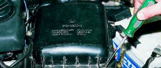
Removing the cylinder head cover
Place the machine on a pit or ramp.
First, the holders of the brake booster pipe and the throttle valve drive cable should be disconnected from the cylinder head cover. They are mounted on special brackets on the left and right sides of the block.
Next, use a 10mm wrench to unscrew the bolt securing the air duct couplings. Move it aside. Next, using a screwdriver, slightly loosen the clamp of the crankcase ventilation pipe, which connects it to the air duct. Now use a 10mm socket to unscrew the bolts holding the cylinder head cover. The order is not important here.
OLYMPUS DIGITAL CAMERA
After that remove:
- brackets for the throttle cable and motor screen;
- lid pressure washers;
- ventilation and air hoses.
Next, all that remains is to remove the cylinder head cover.
Tightening torques for Chevrolet Aveo T250 threaded connections
| Application | Nm, (rotary angle) |
| Compressor piping screw | 33 |
| Compressor mounting screws | 27 |
| Compressor mounting screws | 50 |
| Air filter housing mounting screws | 12 |
| Generator adjusting bolt | 20 |
| Generator mounting bolt | 20 |
| Connecting rod bearing cap bolts | 25 +30° +15° |
| Coolant pump mounting screws | 10 |
| Coolant temperature sensor | 20 |
| Camshaft bearing cover screws | 50 + 45° + 15° |
| Crankshaft pulley mounting screw | 95 +30° +15° |
| Camshaft Position Sensor Bolt | 10 |
| Cylinder head mounting screws | 25 + 60° + 60° + 60° +10° |
| Ignition coil mounting screws | 10 |
| Ignition coil plate mounting screws | 10 |
| Engine lift bracket bolt | 25 |
| Engine mount nuts | 40 |
| Engine Mount Fastener Bolts | 60 |
| Engine Mount Bolts | 60 |
| Exhaust Pipe Bolts | 40 |
| Nuts securing the exhaust pipe to the catalytic converter or connecting pipe | 30 |
| Nuts securing the exhaust pipe to the exhaust pipe | 40 |
| Exhaust pipe heat shield mounting screws | 15 |
| Exhaust pipe nuts | 25 |
| Flex plate mounting screws | 60 |
| Flex Plate Inspection Cover Screws | 10 |
| Flywheel mounting screws | 35 +30° +15° |
| Flywheel inspection cover mounting screws | 12 |
| Beam bolts | 25 |
| Intake manifold nuts | 25 |
| Intake manifold support bracket mounting screws | 22 |
| Fastening screws for the lower cover of the timing belt of the camshaft drive | 10 |
| Oil sump mounting screws | 10 |
| Oil pan drain plug | 55 |
| Oil pressure sensor | 40 |
| Oil pump mounting screws | 10 |
| Screws for securing the support bracket and oil pump (supply tube) | 10 |
| Oil pump pressure reducing valve | 30 |
| Oil pump rear cover screws | 6 |
| Power steering pump mounting screws (hereinafter referred to as power steering) | 25 |
| Power steering pump pulley mounting screws | 25 |
| Screws for securing the rear cover of the camshaft drive timing belt | 10 |
| Right shift bracket mounting screws | 60 |
| Spark plug | 40 |
| Thermostat housing mounting screws | 20 |
| Throttle cable bracket mounting screws | 8 |
| Automatic tensioner bolt for camshaft timing belt | 20 |
| Screws for fastening the gear shift basket housing | 75 |
| Shift mechanism mounting screws | 45 |
| Screws for fastening the upper cover of the camshaft drive timing belt | 10 |
| Valve cover screws | 10 |
Video about “Tightening torques for threaded connections” for Chevrolet Aveo
Tightening torque, torque wrench, fastener strength and handy table
Tightening the connecting rods, checking the correct installation of the pistons
The tightening torque of threaded connections, why is it so important?
Replacing the cylinder head gasket
After completing the previously described steps, they begin to replace the gasket itself on the Chevrolet cylinder block. First of all, dismantle the camshaft along with the bearings, disconnecting them from the cylinder head studs. In order not to suffer later, set the marks using a ratchet wrench and remove the shaft gear.
Next, the drive levers of the Chevrolet engine valves are disconnected, and then the hydraulic mounts are turned out.
Then:
- disconnect the oil pipes from the hydraulic supports;
- disconnect the sensor blocks of the Niva throttle valve, IAC (idle air control), detonation, coolant temperature, as well as the wires leading to the injectors;
- unscrew the cables from the spark plugs;
- find the sensor that controls the temperature of the antifreeze, slide the protective cap on it and disconnect the wire from it;
- Disconnect the exhaust pipe from the exhaust manifold;
- unscrew the bolts holding the inlet hose on it and move it to the side;
- use a screwdriver to loosen the clamps and disconnect the pipes of the absorber, thermostat, fluid supply to the radiator and heater;
- separate the fuel supply pipes from the cylinder head;
- remove the starter protective shield and Chevrolet chain tensioner;
- unscrew the power steering pump bracket from the engine;
- remove the camshaft chain and gear.
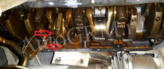
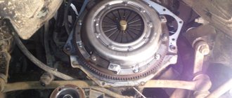
Afterwards, you need to unscrew all the bolts securing the cylinder head - there are 10 of them. To do this, use an E-Torx type wrench. Dismantle the Chevrolet block head itself (it is heavy - it is better to do this with a partner).
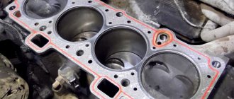
Next, the old gasket is removed. It sticks quite strongly to the base, so you will have to scrape off its fragments - try not to leave scratches. Sand the clean surface further and make sure that no debris gets into the coolant supply channels.
A new gasket is put in place and the cylinder head is placed on it. The latter is fixed in a certain order. To do everything correctly, check this diagram.
The bolts are first fixed so that the torque wrench shows 20.0 Nm. The final tightening is done with a torque of no less than 70 Nm and no more than 85. After this, the bolts in the same order are additionally turned 90 degrees with a wrench in two stages.
The Niva engine is assembled in the reverse order. Don't forget to add fresh coolant.
If you do not have confidence in your own abilities, then it is better to entrust the replacement of the gasket to specialists.
Any engine sooner or later requires repair, especially when the car has to be operated in difficult conditions, which is important for jeeps, which is what the Chevrolet Niva is.
Independent Wheel Bearing Clearance Repair
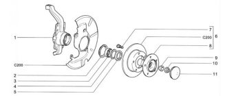
If you feel or feel vibration in the steering column while driving, then most likely the clearance on the front wheels in the bearings of the hub itself has increased, so their service life will be reduced, and the tires will begin to wear unevenly. And if there is no gap at all, then the hub will rotate tightly, which will also lead to a decrease in service life, so its gap should be greater than zero fifteen ml. Adjustment of the front bearings is carried out using a wheelbrace wrench, a twenty-seven wrench and a hammer.
- A wheel that is in a suspended state should be rocked; if there is play, the gap must be adjusted. After this, press the brake pedal and rock the wheel; if there is no play, then there is a gap in the bearings.
- It is necessary to dismantle the decorative cap and unscrew the lock nut from the hub, and hold it with a wrench to prevent it from turning. When repairing the chassis while adjusting the hub, it is advisable to install new hub nuts, since even after adjustment there is a high probability that the old ones will take their original place, which will not allow them to be properly locked. If this is not possible, then you can take the nut from Drugov’s car.
- Then you need to twist the hub nut so that the torque is 19.6 Nm. turning the hub several times, ninety degrees in two directions, will install the bearing itself. After this, loosen the adjusting nut and tighten it to 6.8 Nm. Having done all this, simply unscrew the nut twenty-five degrees.
- After everything is done, change the collar of the nut on the pin of the external drive joint.
- After the adjustment is made, check how the wheels rotate; if they rotate easily, then everything is fine. The final check can be made only after driving several kilometers without braking, assessing how the hub heats up.
Also interesting: Suspension lift in the field yourself
When should you change the cylinder head gasket?
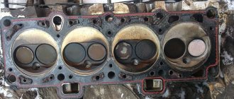
Such work will have to be done when the gasket is damaged. These could be cracks or holes in the gasket. If damaged, the car owner will observe the appearance of air in the cooling system . This will also be indicated by the bubbling of antifreeze.
Crack in the cylinder head gasket.
You will also need to change the gasket when there is not enough compression in the combustion chamber. In this case, the gasket may simply wear out and will no longer be able to perform its functions. Also, when cracks appear, antifreeze will enter the combustion chamber, which will lead to unstable engine operation.
The cylinder head gasket on the Shniva burned out.
In all of the above cases, replacing the gasket will be simply necessary . If you do not replace it in time, the consequences can be dire.
Video about the signs of a broken cylinder head gasket in a Niva Chevrolet
Spark plug torque
To repair and install spark plugs, a special tool is used, which is called a torque wrench, and this should not be forgotten. You also need to understand that not only the diameters of the threads in the engine housing itself differ, but also the tightening torque for each car manufacturer is different.
Therefore, experts talk about the importance of understanding the “torque” of the spark plug being installed. Everything depends not only on the structure of the thread itself, but also on the force with which installation is carried out
If you need to mount a candle, but there is no specialized tool at hand, then installation using improvised tools is allowed. In order to understand with what force the candle should be tightened, you first need to become familiar with it. Most often, manufacturers leave information of this nature on the packaging or in the product manual. In addition to a detailed diagram, as well as the correct installation sequence, such instructions most often include information about the thread of a given candle. Before you begin installing candles, a number of necessary conditions must be met. The first rule that must be followed is to carry out installation only when the engine is cold. You should also thoroughly clean the threads from carbon deposits.
Initially, the candle should be screwed in by hand, but you should not be too fanatical in this matter and screw it in all the way. After you have secured the spark plug, you should tighten it with a spark plug wrench a few turns. The number of revolutions in this case depends on the type of gasket used, as well as the size of the thread. For example, for a standard type of spark plug with an M14 thread, 180 degrees, that is, 20 Nm, will be sufficient. Information about the thread size can be found on the packaging or on the candle body itself (sometimes engraving is done on the insulator).
You should not screw the part all the way in, as in this case you can damage the already fragile threads not only on the spark plug itself, but there is also a high probability of damaging the groove in the engine, which is fraught with more serious consequences. In order to install a candle you do not need a lot of experience or knowledge of technical literature
The most important thing in this matter is to be careful, and it is also a good idea to familiarize yourself with the information provided by manufacturers
Replacing the cylinder head gasket on a Niva Chevrolet
To replace the gasket and put it on correctly, you will need to prepare:
- Open-end wrenches for “10” and “13”.
- Extension cords.
- Collar.
- Hammer.
- Torque wrench.
- Ratchets.
- Flathead screwdriver.
It should be said that work should only be done with the engine removed. This way the process can be greatly simplified. If it is not possible to remove the engine, then you can make repairs on the car, first freeing up space.
Instructions:
- Remove the cylinder head cover.
Removing the cylinder head cover - Place a container under the engine where oil and antifreeze will drain.
- Disconnect the throttle valve drive cable.
Disconnect the throttle cable - Remove the timing pulley and bearing housing.
Remove the bearing housing along with the camshaft - Next, you need to disconnect the wires from the antifreeze and idle speed sensors. Disconnect the wire from the idle air control sensor Disconnect the wire from the throttle position sensor Disconnect the wire from the coolant temperature sensor
- Disconnect the injector power connector.
Disconnect the injector power connector - Disconnect the cable from the spark plugs.
Disconnect the wires from the spark plugs - Disconnect the intake manifold pipe.
Disconnect the intake manifold pipe - Disconnect the cooling system pipes.
Disconnect all pipes of the cooling system - Disconnect the fuel supply and drain pipes using open-end wrenches.
- Remove the drive chain tensioner from the pulley.
Dismantling the drive chain tensioner - Disconnect the power steering mounting brackets.
Disconnect the power steering bracket from the engine - Remove power steering.
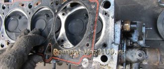
- Remove the cylinder head.
Removing the cylinder head
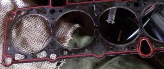
After this, you should remove the old one and install a new gasket , having first lubricated the places where it connects to the motor with sealant. At this point the work can be considered completed. Assembly is carried out in reverse order.
Installing a new gasket
In order for the cylinder head to fit tightly to the block itself, it should be properly tightened.
Tightening sequence for cylinder head bolts
- Using a torque wrench, tighten the first to tenth bolts in a certain sequence (the diagram can be viewed in the car’s operating instructions). The tightening should be 20 Nm .
Bolts should be tightened in the sequence shown in the diagram. - After this, you need to tighten all the bolts again, but with a force of 70-75 Nm .
- Then all the screws should be turned 90 degrees (this must be done in two stages, turning the bolts 90 degrees each time).
At this point the work is considered completed. If it was done correctly, the engine will operate stably, and antifreeze will no longer enter the combustion chamber .
If you tighten the head incorrectly, individual bolts may not be tightened or overtightened, which will also lead to problems. For example, under-tightening will cause an antifreeze leak, and over-tightening can lead to cracks appearing on the power unit.
Independent Wheel Bearing Clearance Repair
If you feel or feel vibration in the steering column while driving, then most likely the clearance on the front wheels in the bearings of the hub itself has increased, so their service life will be reduced, and the tires will begin to wear unevenly. And if there is no gap at all, then the hub will rotate tightly, which will also lead to a decrease in service life, so its gap should be greater than zero fifteen ml. Adjustment of the front bearings is carried out using a wheelbrace wrench, a twenty-seven wrench and a hammer.
- A wheel that is in a suspended state should be rocked; if there is play, the gap must be adjusted. After this, press the brake pedal and rock the wheel; if there is no play, then there is a gap in the bearings.
- It is necessary to dismantle the decorative cap and unscrew the lock nut from the hub, and hold it with a wrench to prevent it from turning. When repairing the chassis while adjusting the hub, it is advisable to install new hub nuts, since even after adjustment there is a high probability that the old ones will take their original place, which will not allow them to be properly locked. If this is not possible, then you can take the nut from Drugov’s car.
- Then you need to twist the hub nut so that the torque is 19.6 Nm. turning the hub several times, ninety degrees in two directions, will install the bearing itself. After this, loosen the adjusting nut and tighten it to 6.8 Nm. Having done all this, simply unscrew the nut twenty-five degrees.
- After everything is done, change the collar of the nut on the pin of the external drive joint.
- After the adjustment is made, check how the wheels rotate; if they rotate easily, then everything is fine. The final check can be made only after driving several kilometers without braking, assessing how the hub heats up.
Also interesting: Chevrolet Niva instrument cluster tuning
conclusions
If you do not have sufficient skills in this work, it is recommended to seek help from specialists at a service station.
Video about replacing the cylinder head gasket in a Niva Chevrolet
| The cylinder head gasket is replaced if it is damaged. |
| The main signs of damage to the head gasket: |
| – insufficient compression (below 1 MPa (10 kgf/cm2)) in one or more cylinders; |
| – breakthrough of gases into the cooling system (seething, foaming of liquid in the radiator, rapid drop in the liquid level in the expansion tank in the absence of external leaks); |
| – coolant entering the lubrication system (emulsion on the oil level indicator, stratification of oil drained from the crankcase - especially noticeable in a transparent container); |
| – oil getting into the cooling system (oil film on the surface of the liquid in the expansion tank). |
| You will need: a torque wrench, a screwdriver, pliers, wrenches (regular and socket) “8”, “10”, “13”, “17”, E-Torx head. |
|
Characteristics of the camshaft VAZ 21213
VSKh of Niva engines depending on the installed camshafts
"DYNAMIC CAMS" camshafts for VAZ classic engines
| 21213 — 1006010 — | 80 | 03 | 37 | 48(48G) | 71 | 72(72G) |
| For engines with volume, cm 3 | 1200 1300 1450 | 1450 1600 | 1600 1700 | 1600 1700 | 1700 1800 | 1700 1800 |
| Valve lifts, mm intake exhaust | 10,4 10,1 | 10,8 10,4 | 11,4 11,8 | 11,6 10,9 | 12,0 11,3 | 12,2 11,4 |
| Opening advance to BDC of the exhaust valve, deg. | 44 | 45,5 | 51 | 62 | 56 | 68 |
| Closing delay after BDC of the intake valve, deg. | 53 | 57,5 | 64 | 75,5 | 71 | 84 |
Note: 1. The phases are shown when setting the valve overlap point to TDC. 2. Allowable displacement of the valve overlap point from TDC -3. 0 deg. according to the angle of rotation of the crankshaft. 3. Camshafts 37, 48, 71 and 72 require modification of the cylinder head 4. Camshafts are not intended for use with hydraulic compensators. 5. Modifications of 48G and 72G camshafts are available, designed to work in tandem with a hydraulic compensator.
"DYNAMIC CAMS" camshafts for VAZ classic sport engines
| 21213 — 1006010 — | M3 | M4 |
| Valve lifts, mm intake exhaust | 13,0 12,5 | 12,5 12,7 |
| Opening advance to BDC of the exhaust valve, deg. | 70 | 75 |
| Closing delay after TDC of the exhaust valve, degrees. | 72 | 67 |
| Opening advance to TDC of the intake valve, degrees. | 63 | 63 |
| Closing delay after BDC of the intake valve, deg. | 89 | 96 |
| Valve overlap height, mm | 5,1 | 5,1 |
Note: 1. The phases are shown when setting the valve overlap point to TDC. 2. Actual valve lifts may differ from those indicated within 0.5 mm depending on the position of the valve end relative to the center of the lever swing. This installation requires additional developer instructions.
For those who like more precise tuning of the car, camshafts No. 48 (48G), 71, 72 (72G) are recommended to be installed with an adjustable split sprocket. Almost every shaft can be adjusted for the city and for the highway, shifting the valve overlap point before or after TDC by up to 7 degrees. If the overlap point is before TDC, the car will have a low-level characteristic, i.e. will add torque at low speeds, losing it at high speeds. This is useful in the city. And vice versa. When installing shaft No. 37 on a 1.5L engine, it will be a top-mounted one. When set to 1.7 - low. This trend is observed with all shafts. When the cubic capacity increases, it is more advisable to install a top shaft, since the bottoms increase due to an increase in the working volume, and power at high speeds increases due to improved filling due to the shaft providing a larger time-section. Moreover, the higher the cubic capacity. This effect is even more pronounced. If we set the bottom shaft (say 80) to a volume of 1.8, we will get an excellent tractor that will move anything, but will not be able to go fast: after 3000 rpm the engine will die, you can turn it only for noise. If you put shaft No. 71 on a 1.5 engine, it will easily spin at 8000 rpm, but it will actually go only after 4000 rpm, and you will need to start at high speeds, igniting the clutch. Don't go wrong with your shaft choice. Camshafts 71 and 72 require modification of the cylinder head, which consists of countersinking the valve seats by 1.2-1.4 mm (r/v 71-72) and subsequent grinding. This must be done, firstly, for the correct location of the swing axis of the valve drive lever relative to the end of the valve, and, secondly, to increase the permissible spring travel. Camshafts 37 and 48 can be installed without modifying the valve seats, although after countersinking the seats by 0.8-1mm (r/v 37-48), the result will be better. Camshafts are not designed for use with hydraulic lifters. Modifications of 48G and 72G camshafts are available, designed to work in tandem with a hydraulic compensator.
| Name of product | Retail price |
| 80 | 3 100 rub. |
| 03 | 3,200 rub. |
| 37 | RUB 3,400 |
| 48 | RUB 3,600 |
| 48G | RUB 3,600 |
| 72 | RUB 3,800 |
| 72G | RUB 3,600 |
| M3 | 4,500 rub. |
| M4 | 4,500 rub. |
In my opinion, to compare the VS characteristics of different camshafts, it is necessary to evaluate the area under the curve limited by the desired engine speed.
There are also many more camshafts for which VSCs have not yet been discovered.
VSH “close relative”, VAZ 2103 (for comparison).
External speed characteristic of engine 21213
Eliminating the causes leading to the appearance of oil in the pipe
Factors leading to an increase in crankcase gas pressure and, as a consequence, to the appearance of oil in the air filter duct were discussed above. The first of these is a high level of lubricating fluid in the engine crankcase. When the oil is above the maximum level, the internal free volume of the crankcase decreases, which leads to an increase in pressure in it. In this case, it is necessary to drain the excess and subsequently try to maintain the engine lubrication level in the middle between the MAX and MIN marks on the dipstick.
When the air filter is clogged, this not only leads to a decrease in engine power and the possibility of a number of other malfunctions, but also to a change in pressure in the crankcase. When the motor does not have enough air, excess pressure is created in the air supply channels. If all connections are sufficiently sealed, then the missing volume of gas is sucked through the breather connected to the filter pipe from the crankcase. So in this case, oil vapors enter the air duct. A simple and quick way out of this situation is to replace the air filter (if it is really dirty and the reason for the appearance of oil in it).
It is clear that if the crankcase ventilation system (channel) does not work (clogged), then there will be increased gas pressure in the latter. We are talking about special channels in the cylinder block and a thin hose between the throttle valve and the valve cover. These means of crankcase ventilation tend to coke if low-quality or old oil that is not replaced on time is used, which begins to lose its properties, turns into a resin state and clogs the internal lumen of the channels. Also, in winter, in severe frost, these crankcase ventilation systems can freeze - accumulated condensate gets trapped in them.
In the latter case, it is enough to run the engine at idle speed and it is better to do this as a preventative measure for about half an hour each time you start it in the morning. If the ventilation channels are clogged with dirt and oil, you will have to clean and rinse them. Start with the tube between the throttle body and the valve cover. If this does not help, you will have to open the engine and clean the channels in it. It is better to entrust this work to specialists.
The case where the cause of oil getting into the pipe was an exhaust system clogged with molten catalyst is extremely rare. It is described only once and for the VAZ 21124 car. The author (owner of the car) of this story claims that in his car the air filter itself was filled with oil. After all the washing and cleaning of the engine, adjustment and replacement of some parts, no changes occurred. There was no time to disassemble the engine itself, since it did not smoke, although it was dull, it ate a lot of fuel, and besides, a melted catalyst was suddenly discovered. After cleaning the exhaust system, according to the author, the car began to work perfectly and the air filter pipe has not been contaminated with oil leaks since then.
Types of faults
In addition to what is stated above, problems may also arise in which the cylinder head requires complete replacement, these include:
- When the tightness of the CO channels is broken and the engine overheats. A crack begins to appear in the water jacket, thereby mixing with engine oil, which leads to serious problems.
- Warping occurs between the block and the mating surface. At the same time, coolant begins to leak into the engine and out. This malfunction is almost impossible to eliminate, so most often a complete replacement of the part is required.
Required Tools
The replacement procedure is practically the same for various modifications of Niva, and for this you need to purchase the following types of tools:
- Socket head (size 10) or a simple wrench.
- Ratchet for fixing the head.
- Solvent for cleaning the base.
Most owners of VAZ cars always have this set in their trunk; You can install a new gasket yourself.
Instructions for replacing the valve cover gasket on a VAZ 2121
To install a new Niva valve gasket, you will need to perform the following steps: • Dismantling. Removing the filter will help make access to the element easier: to do this, you need to tighten the nuts around the perimeter (use a 10mm socket). After this, release the rod connected to the gas pedal (relevant for modifying the VAZ 21124 with an injection system). Then you can dismantle the valve cover: just gently lift the head, removing it from the studs.
Rear suspension
Chevrolet Niva is designed for driving on asphalt and off-road. Therefore, the car, in addition to all-wheel drive, has increased ground clearance. The latter performs three functions:
- Reduced shock loads on the body, wheels, bearings.
- Providing traction.
- Reduced body vibrations when driving over uneven surfaces.
The pendant is divided into two parts:
- The front one is shown in the diagram below. Includes four control arms (two on each side), ball joints, telescopic shock absorbers, coil springs and anti-roll bar. The front suspension is independent - vibrations of one of the levers do not affect the position of the other.
- The rear is shown in the diagram below. Includes rear axle beam, torque rods, telescopic shock absorbers and coil springs. The beam rigidly connects the wheels. They cannot oscillate independently. Accordingly, the rear suspension is dependent. This slightly reduces comfort and maneuverability. But the beam increases the rigidity and reliability of the structure.
In addition to the listed parts, the suspension also includes other elements: rubber bumpers, silent blocks, bolts, nuts, fasteners, gaskets, brackets. All of them are subjected to large dynamic and static loads. In addition, the rubber parts of the silent blocks and the boots of the ball joints dry out over time and need to be replaced even after the car has been stored in a garage for a long time.
Checking the condition before starting work
It is faster and more profitable to check the need to replace the shaft on models 2121, 21214 and any other domestic Niva yourself - as well as the installation and dismantling process itself. Moreover, even if the camshaft does not change, it will still have to be removed and repaired (grinded, straightened, balanced). Parts that are severely worn, cracked, or bent must be replaced with a new one.
Preparing for replacement
Before removing the camshaft to replace it or check its condition prepare a set of tools consisting of:
- wrenches;
- torque wrench;
- chisels;
- socket heads for 10, 13 and 17.
At the first stage of shaft removal work, the following actions are performed:
- 1. Removing the negative terminal from the Niva 21213 car battery (2121 and any other domestic modification of this car);
- 2. Removing the cylinder head cover;
- 3. Install the camshaft in a position where the mark on its sprocket coincides with the corresponding protrusion on the bearing housing. And the mark on the pulley is with the protruding part of the shaft drive.
4. Using a chisel, bend the petals at the lock washer of the bolt securing the sprocket.
1. Unscrewing the sprocket bolt of the part being removed (key “17”) and removing it from the hole; 2. Dismantling the timing chain tensioner; 3. Removing the camshaft sprocket (it is recommended to tie a chain to it - this will ensure that there is no jumping; 4. Evenly unscrewing (using a 13mm wrench) all the nuts securing the shaft bearing housing, and removing it from the cylinder head studs along with the camshaft.
5. Unscrewing, using a 10mm socket wrench, the fastenings of the thrust flange to the bearing housing;
6. Removing the flange and then the camshaft.
If it is necessary to replace the valve levers, these parts are also removed immediately after dismantling the shaft . To do this you should:
- Move the presser spring legs to the side;
- Remove the lever;
- Remove the spring.
At the same stage, diagnostics of the condition is performed. If there are noticeable damages (cams are worn by 0.5 mm or more, scratches, grooves and nicks are visible on the surface), indicating the impossibility of repair, proceed to the process of installing a new part. The camshaft, which can be repaired, is brought back into working condition. If the question about the need to replace the camshaft of any Niva model (including 2131 and more modern versions) receives a positive answer, you should purchase a new part. As a rule, they are sold complete with cases. It is worth noting that installing a new shaft requires replacing its rockers and hydraulic compensators, which increases the cost of repairs by approximately one and a half times.
Installation
Before installing the shaft inside the bearing box, lubricate the working surfaces of the journals and cams with engine oil. Now you should install the camshaft so that its pin is located exactly opposite a certain reference point - the upper hole of the thrust flange. The part is fixed and the fasteners are tightened, adhering to certain rules: • the nuts must be tightened, trying to maintain a force of 19 Nm; • twisting is carried out in a certain sequence, which can be seen in the diagram: