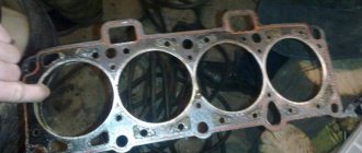
Cylinder head gasket VAZ 2107
The cylinder head gasket is a one-time use item, since its physical properties and geometry change during installation.
What is the cylinder head gasket used for?
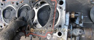
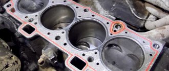
The cylinder head gasket is designed to seal the connection between the cylinder block and the head. Even taking into account the fact that these engine components have perfectly flat mating planes, it will not be possible to achieve complete tightness without it, because the pressure in the combustion chambers reaches more than ten atmospheres. In addition to this, the seals also require connection of the oil channels, as well as the cooling jacket channels. Tightness is achieved by uniform compression of the gasket while tightening the connecting elements.
The gasket serves to seal the connection between the head and cylinder block
What are cylinder head gaskets made of?
The cylinder head gasket can be made of different materials:
- metal (copper and aluminum alloys);
- asbestos;
- combinations of metal and asbestos;
- combinations of rubber and asbestos;
- paronitis.
The main requirements for the gasket are resistance to high temperatures and ability to compress. Each of the listed materials has its pros and cons. Products made from multiple layers of metal or asbestos, for example, better withstand high temperatures, but may not provide the best seal. Parts made of rubber and paronite, on the contrary, maximize the connection between the head and the block, but their temperature stability is lower.
Metal cylinder head gaskets for VAZ 2107 are made from copper and aluminum alloys
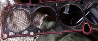
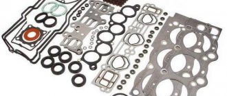
When choosing a gasket, it is better to give preference to a combined product, for example, made of asbestos and metal. Such seals are made of sheet asbestos, but the holes for the cylinders are reinforced with metal rings. Holes for fastening elements are reinforced with the same rings.
When choosing a gasket, it is better to give preference to a combined product
What to consider when choosing a cylinder head gasket
If you are going to replace the gasket, you need to know exactly the characteristics of the engine. The fact is that the “sevens” were equipped with three types of power plants: VAZ 2103, 2105 and 2106, which have different cylinder diameters. For the first it is 76 mm, for the last two it is 79 mm. Gaskets are manufactured according to these dimensions. Therefore, if you purchase a cylinder head seal for a 2103 engine and install it on a 2105 or 2106 power unit, the pistons will naturally tear the edges of the product with all the ensuing consequences. If a gasket with a cylinder hole diameter of 79 mm is installed on a VAZ 2103 engine, the seal will not provide the necessary tightness due to the fact that the part will not completely block the cylinder holes.
Causes and signs of cylinder head gasket failure
The destruction of the seal is characterized by its breakdown or burnout. In the first case, there is slight damage to the part, which in some cases cannot even be seen with the naked eye. When a product burns, the scale of damage is significantly greater. The part is deformed and loses its integrity, leaving joint areas without sealing.
Causes of destruction
The main reasons why a cylinder head gasket fails prematurely include:
- overheating of the power unit;
- incorrect order or tightening torque of the mounting bolts during installation;
- factory defects or low quality materials used to manufacture the part;
- use of low-quality coolant;
- engine malfunctions.
Engine overheating most often causes gasket failure. It usually occurs due to interruptions in the operation of the cooling system (malfunction of the thermostat, radiator fan, fan switch sensor, clogged radiator, etc.). As soon as the driver drives a car with an overheated engine for half a kilometer, the gasket will burn out.
When installing a new seal on a power unit being repaired, it is important to follow the order of tightening the bolts that secure the head to the block. In addition, it is necessary to adhere to the specified tightening torque of the fastening elements. If the bolts are not tightened or overtightened, the gasket will inevitably become deformed and subsequently be punctured.
Most often, the gasket burns out due to engine overheating.
When choosing a replacement seal, you should pay attention not only to its parameters, but also to the manufacturer. Under no circumstances should you buy cheap parts from unknown companies. The result of such savings may be unplanned engine overhauls. This also applies to coolant. Low-quality refrigerant can cause corrosion and damage not only the gasket, but also the head itself.
As for disturbances in the operation of the power plant, processes such as detonation and glow ignition also have a destructive effect on the seal. Therefore, it is worth monitoring the quality of the fuel and the correct adjustment of the ignition timing.
Signs of cylinder head gasket damage
A breakdown or burnout of the gasket can manifest itself in the form of:
- rapid heating and overheating of the engine;
- unstable operation of the power unit;
- oil or coolant leaks from under the cylinder head;
- traces of coolant in the oil and grease in the refrigerant;
- steam in exhaust gases;
- an increase in pressure in the cooling system, accompanied by the appearance of smoke in the expansion tank;
- condensation on the spark plug electrodes.
Symptoms will be different in each individual case. It depends on where exactly the integrity of the seal was damaged. If the gasket is damaged near the edge of the cylinder bore, then, most likely, the power plant will overheat with an increase in pressure in the cooling system. In this case, hot exhaust gases under pressure will break through the seal damage into the cooling system. Naturally, antifreeze or antifreeze will begin to heat up quickly, increasing the temperature of the entire engine. This will increase the pressure in the system, and gas bubbles will appear in the expansion tank.
When a gasket burns out, refrigerant often gets into the oil.
There will definitely be a reverse effect. If coolant enters the combustion chambers, it will disrupt the normal operation of the engine. The engine will begin to stall due to the fact that the fuel-air mixture, diluted with coolant, will not be able to burn. As a result, we will get a noticeable malfunction of the engine at idle, accompanied by exhaust gases in the cooling system, coolant in the combustion chambers and thick white smoke with a characteristic odor from the exhaust pipe.
If the gasket burns out somewhere between the windows of the cooling jacket and the oil channels, it is possible that these two process fluids will mix. In this case, traces of grease will appear in the expansion tank, and antifreeze or antifreeze will appear in the oil.
Oil may get into the cooling system
If the gasket is damaged along the edge, oil or coolant leakage is usually observed at the junction of the cylinder head and the cylinder block. In addition, a breakthrough of exhaust gases between the main engine parts is also possible.
If the gasket is damaged and coolant is leaking into the cylinders, thick white smoke will come out of the exhaust pipe.
Self-diagnosis
Diagnosis of gasket failure must be approached comprehensively. In other words, you should not immediately start removing the head when you see white smoke from the exhaust pipe or oil leaks from under the head. To verify that the seal is faulty, follow these steps:
- Inspect the junction of the head and cylinder block around the perimeter. If you find oil or coolant leaks, make sure that it is leaking from under the head.
- Start the engine and notice the color of the exhaust and its smell. If it really looks like thick white steam and smells like antifreeze or antifreeze, turn off the engine and carefully unscrew the expansion tank cap. Take a sniff. If exhaust gases enter the cooling system, the smell of burnt gasoline will come from the tank.
- Without tightening the cap of the expansion tank, start the engine and look at the condition of the refrigerant. It should not contain any gas bubbles or traces of lubricant.
- Turn off the power plant and let it cool. Remove the oil dipstick, inspect it and determine the oil level. If there are traces of a white-brown emulsion on the dipstick, or the oil level has suddenly risen, mixing of process fluids is taking place.
- Let the engine run for 5-7 minutes. Silence it. Unscrew the spark plugs and inspect the electrodes. They must be dry. If there are traces of moisture on them, most likely, refrigerant is entering the cylinders.
Video: signs of cylinder head gasket damage
The procedure for removing the cylinder head on a VAZ 2109
Before you begin removing the VAZ 2109 head, you need to do some preparatory work:
The first step is to remove the air filter housing
Then you need to disconnect the fuel hoses and power wires from the injector or carburetor (it all depends on what kind of engine you have installed)
- You also need to drain the coolant from the system.
- Disconnect the pants from the exhaust manifold
- Disconnect high voltage wires
- Unscrew and remove the valve cover.
In general terms, we need to free the head from everything unnecessary so that nothing interferes with us during removal. If you make a complete replacement, you will also have to remove the carburetor and manifolds. But if you only need to change the gasket on the VAZ 2109, then you can do it without, as they say, unnecessary movements.
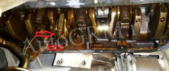
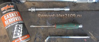
In order to unscrew the cylinder head on a VAZ 2109, we use a hexagon and a powerful wrench. In general, you will need to unscrew ten mounting bolts, as shown in the picture.
You can use the lever to select the desired pipe.
We take out the bolts and washers, as we see in the picture.
Now very carefully lift the head of the VAZ 2109 block up, removing it from the block.
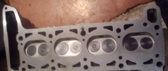
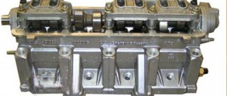
Cylinder head
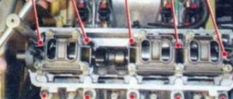
Essentially, the head is the cylinder block cover that covers the cylinders. It contains the upper parts of the combustion chambers, spark plugs, intake and exhaust ports, as well as the entire gas distribution mechanism. The VAZ 2107 cylinder head is a monolithic part cast from an aluminum alloy, but inside it there are channels where oil and coolant circulate.
The head is the housing for the timing mechanism
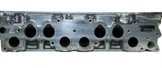
Are there any differences in the design of the cylinder head for the carburetor and injection engines of the VAZ 2107
The cylinder heads of the carburetor and injection engines of the “seven” are almost the same. The only difference is the shape of the intake channels. For the former it is round, for the latter it is oval. A manifold from a carburetor car without modifications will not be able to completely block the intake windows. Therefore, if there is a need to replace the head, this point should be taken into account.
The device of the cylinder head of the VAZ 2107
The main task of the cylinder head is to ensure the operation of the gas distribution mechanism. It serves as a housing for all its elements:
- camshaft assembly with “bed”;
- levers;
- valves;
- valve seats;
- guide bushings;
- oil seals;
- springs;
- "plates";
- "crackers";
- retaining rings;
- adjusting bolts with bushings, etc.
The valve mechanism is part of the cylinder head
Beginning
The first step is to disassemble the air filter. Of course, on a carburetor engine it is a little easier to remove. If you have an injector, you will have to tinker with its rubber mounts. But the essence remains the same. you need to completely disassemble the fuel system to get to the cylinder head. But we will not consider injection, but the carburetor is seven. However, there are still many classic cars with this power system.
It is advisable to remove the carburetor because if you remove the head from it, you may accidentally damage it. On all cars of the classic series, the carburetor is removed in the same way. This procedure is quite simple, but will take some time. Now you can unscrew the nut that secures the distributor and remove the distributor along with the wires. Closer to the engine it remains small. drain the antifreeze from the system.
And then disconnect all the pipes that you see. After this, you can remove the cylinder head cover. It is secured with nuts and washers. Don't lose them during repairs. That's all, the preparation is complete, the hardest part can begin. disassembling and installing the block head.
READ Installing Cruise Control Skoda Octavia Tour
How to grind in correctly - the process of completing the work
The grinding process begins with desiccation of the valves. First, we place an object under the valve plate that serves as a stop for it.
To facilitate the memorization process and to ensure that errors are eliminated when installing rockers, experienced car enthusiasts recommend removing and grinding the valves one at a time. A popular way to remove valves is using a special puller (purchased at a car dealership or car market), but sometimes the crackers on the cone stick and are not immediately removed. In this case, according to the experienced Kulibins, you can take a tube of suitable diameter and, placing it on the top of the valve (cracker), lightly “bale” it with a hammer. A light blow breaks off the crack if it is stuck and makes it easier to remove the valve with a puller.
After removing the spring, pull the valve out of the seat and visually inspect it. After a long period of work, even if it hasn’t burned out, there is still carbon deposits on it, so we grind in the valves. To do this, you will need a special grinding powder or paste (Permatex Valve Grinding Compound, GOI paste, VPM-Auto, M-14 - M-40, etc.). The pastes are used immediately, and the powders are diluted with engine oil, resulting in a viscous substance that is applied to the chamfer of the valve plate. Pastes and powders have different grain sizes: coarser for initial grinding, finer for final grinding.
After spreading the bevel of the seat with paste or diluted powder, insert it back into the seat, press lightly and turn so that the paste is evenly distributed along the bevel of the plate and hits the seat. After this, on the back side of the cylinder head, attach the chuck of a drill or screwdriver to the valve stem (a drill is better because it has more pure revolutions).
Important! Do not distort the drill under any circumstances in order to grind the valves correctly.
It is better to carefully pull the drill up with your fingers, resting them in the area of the chuck, and holding it by the handle
First, the drill should work in one direction for a while, then switch to the opposite direction (turn on reverse). After several minutes of work in each direction (1 minute in each direction), the valve is removed and inspected. The result is visible to the naked eye; the valve seat is shiny or matt gray. If inclusions or stains remain, repeat the procedure, applying finishing paste. The same applies to the saddle, if it has inclusions, shells or uneven color, the grinding is repeated. If the valve is properly ground to the seat, it is installed in place, having first replaced the oil seal with a new one.
Important! Valve seals MUST be changed! This is a one-time use item. Otherwise, all the work will go down the drain, the valve will feel loose in the seat, will not provide a complete seal, and oil will flow through it into the cylinders. Something else useful for you:
Something else useful for you:
- How to Replace Valve Guides
- Self-adjustment of valve clearances on a VAZ 2110
- Crankshaft position sensor - check, device, signs of malfunction
The oil seal is removed using pliers. They grab the oil seal and, turning it from side to side, remove it from the groove. The main thing is not to hit the guide bushing so as not to damage it.
When the old oil seal is removed, install a new one. To do this, it is recommended to insert the valve into the seat so that it serves as a guide and facilitates the installation process. The new oil seal is placed on the valve stem, a tube of suitable diameter is taken, and by lightly tapping the tube with a hammer, we put the oil seal in place. We can tell by the sound that the seal is in place. At first it is heard only in the area of the oil seal, and after it is in place, the sound begins to spread throughout the cylinder head.
Don’t forget that a hole is formed at the end of the rod, which we must remove. If you leave it, the motor will run intermittently. It can be easily ground, for example, on a sharpening machine, the main thing is that the surface of the end of the rod is smooth (even slightly convex is allowed).
Having dried the valve, we move on to the next one. The drying process is simple, even if there is no special puller, use an open-end wrench, but then you will need outside help. One person presses the spring with an open-end wrench, and the other installs the cracker.
Having carefully wiped the end of the valve and the rocker from dust, dirt and mechanical particles, we assemble the unit and install the rocker, securing it with a spring. We move on to the next valve, observing the same sequence of operation.
After grinding in, we check whether the valve is loose or not? The cause of valve play can be either the wear of the guide bushing or the valve itself. If there is wear on the valve, then we can see it with the naked eye, and then it is worth changing it, and if it is in order, then we change the guide sleeve.
Bolts in VAZ family cars
Fasteners are presented in a wide range, they have different sizes and purposes. For example, the rear door shock absorber mounting bolt 2108-09 or the roof support mounting bolt. If you are repairing a generator, you will also need the appropriate fastener. Even to fix a ball license plate, certain hardware is needed.
The photo shows the cylinder head bolts of a VAZ 2108.
Bolts for alloy wheels
VAZ wheel bolts are designed for fixing alloy wheels, the total length is 51 mm. Approximate cost of elements:
- a VAZ M 12×30.5 wheel bolt costs from 35 rubles;
- secret bolts for VAZ-2101-12 set – 280 rubles;
- wheel hardware M12×1, 25×28 zinc from 45 RUR/piece;
- The eccentric bolt on the VAZ (shown in the photo) allows you to install any wheels with a 4×100 drill bit.
Wheel bolts on VAZ for alloy wheels have a thread length of 28, 30 and 33 millimeters. Standard factory fasteners come with dimensions of 12×1.25 with a total length of 44 mm and a thread length of 24 mm.
Transmission mounting bolt
M12×45 brand fasteners are suitable as standard parts for transmissions and gearboxes on VAZ 2101, 2102, 2103, 2104, 2105, 2106, 2107 models. For VAZ gearboxes, M 12×1.24 Belebey fasteners are used.
Arm bolts
A broken beam bolt (rear suspension arm) is usually discovered when trying to perform wheel alignment. The result is a discovered lever that is not properly secured. On VAZ cars, there are no problems replacing the upper arm, since the fasteners are clearly visible and easy to reach. Bend the pressing petal and knock out the 14x243 element. You will have to work longer with the rear fasteners, since you have to remove the hardware through the lower hole in the beam. It is recommended to use a screwdriver or tweezers as tools.
Using available tools, install new bolts. When replacing, do not dismantle the lower arm. When one hardware is unscrewed and removed, the second one must be fully tightened. This will allow fastening without distortion of the lower axis. It is recommended to have a jack on hand, which should be placed under the lower arm mount and at the same time adjust its position. This technique will lighten the load on the bolt and simplify installation.
Reasons for cylinder head gasket failure.
1. Preheating the engine. As a result of overheating, thermal deformation of the cylinder head and (or) cylinder block occurs, resulting in microgaps between the gasket and the surfaces of the head and (or) cylinder block. Gases and (or) oil and (or) antifreeze rush into these gaps, microcracks gradually grow into cracks and targets, and the tightness of the gasket is broken with the development of the symptoms described above. 2. Insufficient engine warming up in the cold season. Before loading the engine, it must be warmed up. When starting the engine, the cylinder head heats up first, since it has a smaller mass compared to the cylinder block and greater contact with hot gases. In a situation where the cylinder head is heated, but the block is not, the same processes occur as when the engine overheats. 3. Detonation. When detonation occurs, pulsating shock waves appear in the combustion chambers (an abrupt increase in pressure to 100 atm with a simultaneous increase in local temperature to 3700 degrees). 4. Insufficient tightening of the head bolts (incorrect tightening during installation, use of used head bolts, destruction of threads in the cylinder block - found in 2AZ-FE engines, etc.) 5. Faulty condition of the cylinder head and (or) cylinder block. On the plane of the head or block, a deviation of more than 0.03 mm is not allowed, scratches, holes and cracks are not allowed. 6. Installing the gasket on unprepared (dirty) surfaces.
Installing a new camshaft
In order to install a new timing shaft, you will need the same tools as to dismantle it. The installation procedure is as follows:
Be sure to lubricate the surfaces of the cams, bearing journals and bearings with engine oil. We install the camshaft in the “bed”. Using a 10 mm wrench, tighten the bolts of the thrust flange. We check how the shaft rotates. It should turn easily around its axis. We set the shaft to such a position that its pin would coincide with the hole on the fixing flange. We install the bed on the studs, screw on the nuts, and tighten them
It is important to follow the established procedure. Tightening torque - within 18.3–22.6 Nm
The nuts are tightened using a torque wrench with a torque of 18.3–22.6 Nm
We do not install the valve cover and camshaft sprocket in place, since it will still be necessary to set the valve timing.
Illusory repair possibilities
It should be said right away that repairing throttle position sensors is extremely rare. Firstly, the part itself, even the most expensive one, costs only a few dollars, and it makes sense to spend the money. Secondly, in most cases it is simply impossible to make repairs, for example, to restore a worn-out base layer. However, in some models you can slightly shift the resistive tracks relative to the slider and thereby extend the life of the device.
So, there is a special screw on the sensors. With its help, the position of the tracks is fixed. If they are already worn out, then you should loosen this same screw, this will change the location of the slider a little, and you can be a little patient with replacing the device. But don't count on long-term respite. Naturally, we remember that the contactless sensor cannot be repaired. This completes the adjustment, repair and replacement of the throttle position sensor, now you can operate the car for several more years and not even think about such issues.
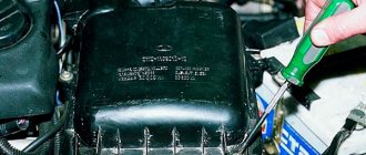
To check the supply voltage, disconnect the wire block from the sensor. Turn on the ignition and use a tester to measure the voltage between terminals “A” and “B” of the wire block. The supply voltage should be about 5V. To check the sensor, we connect the block of wires to it and, with the ignition on, measure the voltage (the wires of the block can be pierced with thin needles connected to the terminals of a voltmeter) between the sensor terminals “B” (“ground”) and “C” (slider) - it should not be more than 0.7V. Turning the plastic sector of the drive by hand, fully open the throttle valve and measure the voltage again - it should be more than 4V. Turning off the ignition, disconnect the wire block and connect an ohmmeter between terminals “C” and “A” (or “B”) of the sensor. Slowly turning the drive sector, we monitor the readings of the tester arrow. There should be no jumps in the needle throughout the entire working range. To replace the sensor, remove the throttle body from the receiver studs without disconnecting the coolant inlet and outlet hoses from it (see Removing the throttle body).
Using a Phillips screwdriver, unscrew the two screws securing the sensor to the throttle body...
...and remove the sensor.
The sensor is marked 2112-1148200
Remove the sealing foam ring installed under the sensor.
Install the sensor on the throttle body in reverse order. In this case, the damper must be in the closed position. The tightening torque for the sensor mounting screws is 2 N•m.
The VAZ 2107 throttle sensor, together with a mass air flow sensor and oxygen concentration control, acts as an element that controls the supply of fuel to the combustion chamber depending on the position of the throttle valve. As with any repair to replace electronic fuel injection sensors, they must be checked for functionality. To check, you will need a regular multimeter with the function of measuring resistance in the power circuit and a set of standard tools.
To check the throttle sensor:
- Disconnect the package with wires from the sensor.
- The connector body will be marked. Connect the ohmmeter leads to terminals “B” and “C”. We open the throttle valve; for a working sensor, the resistance will increase from 2.7 to 8.2 kOhm.
- Next, we switch the multimeter to voltmeter mode and connect its negative terminal to engine ground, turn on the ignition in the circuit, and the positive probe will turn on. For a working sensor, the voltage should be approximately equal to 5V, if absent or significantly different from the norm, there is a malfunction in the power circuit or in the computer. After measuring the voltage, turn off the ignition.
After confirming that the throttle sensor is not working and deciding to replace it, you must:
- To remove the sensor, use a Phillips screwdriver to unscrew the two screws securing it to the throttle body and remove it.
- There will be a foam gasket between the sensor and the housing.
At this point, the repair work to check and remove the VAZ 2107 throttle sensor is completed. The installation must be carried out with the damper closed, aligning the protrusion of the damper axis with the groove on the sensor body.
Sources
- https://carnovato.ru/proverka-regulirovka-datchika-polozhenija-drosselnoj-zaslonki/
- https://www.autofizik.ru/VAZ/VAZ-210721047/features-of-repair-of-a-VAZ-2107-20-with-engine-VAZ-2104/checking-and-replacing-position-sensor-d
- https://remont-vaz2106.ru/datchik-drosselnoj-zaslonki-vaz-2107