Repairing the cylinder head (cylinder head) is a necessary measure associated with a malfunction of the internal combustion engine. Symptoms of malfunction:
- Smokes
- Eats oil
- Doesn't start on first crank with starter
- The engine won't start
- Due to valve breakage
Repair of the cylinder head is carried out after accurately establishing the cause of the malfunction, which can be determined by diagnostic methods, both on the carburetor engine and on the injector.
On a car, the same malfunction can be caused by different reasons. For example, if the engine begins to run intermittently or is tripping, this does not mean that the culprit of the malfunction is the cylinder head. Repair is an expensive operation and therefore first of all it is necessary to determine:
- whether the spark plugs, high-voltage wires and ignition coil work correctly;
- serviceability of fuel injectors;
- presence of a switching signal at the connectors of the injectors and ignition coil;
- whether the fuel pump provides the required fuel pressure in the rail.
If there are no malfunctions in the injection engine control system, you can begin to repair the cylinder head.
Next, let's look at the example of the 8-valve engine of the VAZ family of cars: 2108, 2109, 2110, 2111, 2113, 2114, 2115, Granta, Kalina, Priora, and the basics of repairing the cylinder head.
Cylinder head repair process
Dismantling
On cars with 8 cl engines, the cylinder heads are the same type and interchangeable. Accordingly, all mechanics of actions are carried out regardless of the car model using a single repair technology. When starting to dismantle the cylinder head, general preparation of the vehicle and tools is carried out. The first necessary action is to disconnect the on-board electrical network from the battery. To do this, simply remove the negative terminal from the battery. The second action is aimed at carrying out work related to draining the coolant from the cylinder block by unscrewing the plug located between the third and fourth cylinders. There is no need to drain the fluid from the radiator.
Remove the air filter housing with the rubber pipe by unscrewing the clamp on the throttle assembly. Disconnect the fuel lines from the injector rail.
Disconnect the throttle control cable from the throttle assembly.
Unscrew the two valve cover nuts and remove it. The valve cover gasket must be replaced with a new one during assembly.
After carrying out the general preparatory work, we proceed directly to disassembling the parts and assemblies that prevent the final lifting of the head from the cylinder block.
Unscrew the three bolts of the timing belt mechanism protective cover and remove the cover.
Set the piston of the first cylinder to the top dead center position, while the mark on the camshaft gear should be located opposite the bent bracket of the cover housing.
Fix the position of the crankshaft with a special comb through the inspection hole on the flywheel housing.
Unscrew the nut holding the timing belt tensioner pulley and remove it with a set of washers.
Remove the belt from the camshaft gear and pump and move it to the side.
While holding the camshaft, unscrew the bolt from the gear and remove it.
Unscrew the bolts securing the reflector to the cylinder head housing and cylinder block and remove it together with the pump.
Next, you need to unscrew the two nuts and bolt from the side camshaft cover and remove it, as well as remove the thermostat housing, which is mounted on studs.
Unscrew the nuts securing the upper camshaft bed covers. Remove the covers and camshaft.
Unscrew all the nuts securing the exhaust and intake manifolds and separate them from the head towards the windshield.
The cylinder head mounting bolts are most often made with a Torx key (Torx External). The head of such a bolt has the shape of a six-pointed star and its use is based on the purpose of reducing its size.
Depressurization of valves
Structurally, in the cylinder head, the valve stem passes through a guide pressed into the body of the head. The operation of the valve mechanism is ensured by sequentially assembled parts: lower spring seat, valve stem seal, external spring, internal spring, upper cone seat, retaining nuts.
For further work related to replacing the valve or seat, pressing out the guide bushing, the unit must be disassembled. It is not difficult to carry out the disassembly operation if you have a “dehumidifier” device, which is a system of levers. The end point of the lever is attached to the supporting surface, and the middle part rests with a ring on the upper spring seat. By applying pressure on the spring seat with a lever, access to cone-shaped crackers is opened, which are removed with tweezers.
If you perform desiccation with your own hands and do not have a device, this action can be performed with a hammer blow, having previously selected the mandrel to the size of the upper spring seat.
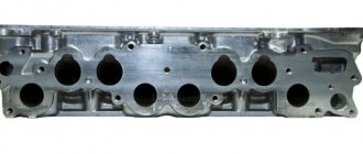
Replacing guides
Valve guides must be replaced if the permissible runout is exceeded, which is no more than 0.6 mm for exhaust valves, and no more than 0.4 mm for intake valves.
The runout is checked using special equipment consisting of a massive plate, which is mounted on the head surface that has already been prepared on a milling machine. A tripod allows you to hold the micrometer in the desired position by moving it vertically and horizontally. Having deflected the valve, inserted into the guide in the direction of movement of the rod until it stops, bring the working head of the micrometer until it touches the valve plate. The arrow on the micrometer is set to zero by rotating the scale and the valve is deflected towards the movement of the micrometer rod. The arrow readings should not exceed 40 divisions for the inlet valve and 60 divisions for the exhaust valve.
If the permissible standards are exceeded, the guide is pressed out with a special drift and a new one is pressed in as well. Then it is processed with sweeps.
It should be borne in mind that the guide for the exhaust valve on the inner surface has a heat-dissipating thread along its entire length, and the intake valve only up to half the length.
Countersink
When installing a new valve guide, the centerline of the valve guide will in most cases not be aligned with the center axis of the seat. To restore the alignment and tight fit of the valve plate to the seat, its edges are processed with special cutters that have three chamfer angles:
- upper correction angle – 300
- valve seat angle - 450
- lower correction angle - 600
A set of cutters for countersinking intake and exhaust valves and mandrels for them can be purchased at specialized retail chains.
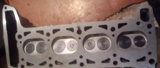
Lapping
Lapping of the seat-valve pair is performed to obtain a tight seal. Lapping is carried out using a drill, a manual collet lever equipped with a return spring, or a pneumatic device with a set of suction cups of different sizes. A composition of grinding powder and motor oil is used as an abrasive, or ready-made lapping pastes are used.
Before grinding, you need to lubricate the valve stem with oil and install the valve in the guide. Then prepare the device and, lifting the valve plate above the seat, place lapping paste along the edge of the plate.
By performing rotational movements around the valve axis in combination with reciprocating movements, the valve is ground into the seat. The appearance of a matte gray belt on the seat chamfer indicates the quality of the surfaces being ground.
Leak test
Upon completion of the grinding operation, finally check the quality of the seal with kerosene with the valves closed. If a kerosene leak is not detected after holding for 2-3 hours, then the cylinder head can be finally assembled. If a leak is detected, the grinding operation should be repeated.
Replacing valve stem seals
Replacement of valve stem seals is mandatory when repairing the cylinder head. During engine operation, options are possible when a defective oil seal (oil seal) flies off the top of the valve guide and moves freely along its rod. A symptom of a malfunction associated with the valve stem seal is the appearance of smoke from the muffler during re-gassing and a slight drop in the oil level in the crankcase. If a malfunction occurs during engine operation, the valve stem seals can be replaced without removing the cylinder head from the engine. It is enough to disassemble the valve cover and remove the camshaft.
Dry out the valve assembly, remove the springs and remove the damaged caps with a special tool (puller pliers, impact collet).
Lubricate the new caps with oil and press them lightly with a hammer through a special mandrel onto the upper part of the guide.
Reassemble the valve assembly and camshaft in reverse order and adjust the valve clearances.
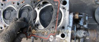
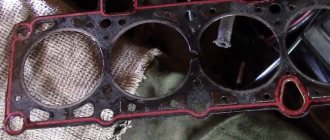
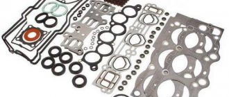
Replacing the cylinder head gasket
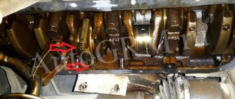
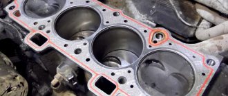
During repairs or in case of damage to the cylinder head gasket, it is necessary to remove the head from the engine. The working part of the surface must be leveled by grinding (this is done more efficiently on a milling machine). Clean the mating surface of the cylinder block from traces of the old gasket, blow air to remove particles and dust, as well as the threaded wells for the bolts securing the head.
Place a new gasket on the surface of the cylinder block and perform installation in the reverse order.
VAZ cylinder head assembly
Assembling the cylinder head must begin after thoroughly purging the surface from foreign objects and particles. Pay special attention to the cleanliness of the internal surfaces of the valve guides and oil supply channels on the camshaft beds. Lubricate the camshaft seats and oil seal, valve stems, tappets and valve stem seals with engine oil.
Insert the valves into the guides (each valve, after grinding in, strictly belongs to the corresponding cylinder). Orient the cylinder head on the table for assembling the valve assemblies and place the lower spring washers. Using a special impact mandrel, press in the valve stem seals and continue assembling the outer and inner springs. Place the upper conical washers on the springs and install the crackers - clamps - with a special tool - a desiccant tool.
The next stage of assembly is the installation of pushers, which, like valves, are inserted in strict accordance with the corresponding cylinder. The final step in assembling the cylinder head is installing the camshaft. The camshaft along with the oil seal is placed on the bed and the covers are placed on top. A thin layer of sealant is first applied to the extreme points of contact with the cylinder head surface. The covers are tightened with nuts and the head is ready for installation on the engine.
Is camshaft seal needed? This is a question that novice motorists ask. Rubber parts, if they are of good quality, do not require additional use of sealant.
Mounting on cylinder block
Before installation, it is necessary to clean and blow with compressed air the surface of the cylinder block from foreign particles, dust, drops of oil and antifreeze.
Place the cylinder head gasket on the surface of the cylinder block and carefully install the head, monitoring its position along the fixing bushings.
Next, the head mounting bolts are installed and 4 stages of tightening are done with a torque wrench:
- 20 N*m.
- 85.7 N*m
- 90°
- 90°
Pulling scheme
The following stages of installation are performed according to the technological process diagram in the reverse order of disassembly described above.
What you need to prepare
First of all, before you start grinding the cylinder head, you need to prepare the tools. The most important thing you need is a set of screws of various sizes and a ruler with a pattern.
In general, the second one will be useful to you only in order to estimate what exactly the head should be like. The entire process is basically done entirely by eye.
- The procedure for adjusting valves with your own hands - tips and recommendations for adjusting valve clearances (90 photos)
- Do-it-yourself adjustment of vase valves - a step-by-step master class on how to quickly and easily adjust classic valves (145 photos and videos)
- Do-it-yourself pump replacement: signs of breakdown, replacement tips and features of installing a new unit (115 photos)
This does not include cases where the process is carried out on a cylinder head grinding machine; there are precise instructions there.
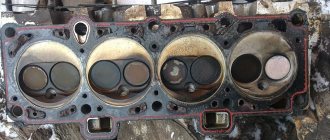
Be sure to check the cylinder head before grinding
You should pay attention not only to dents and changes in the body
We take bright paint, apply it to the surface and literally wipe it off after a couple of minutes.
The paint will remain in cracks and scratches. If you cannot do the procedure yourself, then it is better to find out in advance how much it costs to grind the block head.
Replacing valve seats
If the seats burn out and are destroyed, as well as if the heads are strongly recessed into the body (“sucked”) or have been subjected to repeated countersinking, they need to be replaced. The seats are replaced on a milling machine. The defective seat is bored with a milling cutter and removed from the socket. Then, according to the technology, the head is placed in a thermal oven and heated to 120-150 degrees. Saddle blanks in the form of rings are placed in liquid nitrogen to reduce their temperature to minus 40 degrees. Using tongs, place the cooled rings of future saddles into the sockets and lightly tap them into the body of the head. Further operations for processing seat chamfers are performed on a special milling machine or manually with a set of cutters.
Features of repairing the cylinder head of the Lada Granta
The engine of the Lada Granta car has differences with the Kalina engine. The block head, in comparison with the Kalinovskaya one, has been increased in height by 1.2 mm. This is due to a change in the combustion chamber. Lightweight pistons installed. The timing belt has been modified and operates in a temperature range from minus 40 to plus 40 degrees. The declared belt mileage is up to 200 thousand kilometers.
The main feature of Granta cylinder head repair is the use of metal-ceramic seats. By car Kalina, 2114, etc. Cast iron saddles are used, which can be processed manually using a set of domestic cutters.
Machining cermet seats requires wear-resistant cutting tools. In order to successfully process them, the head is installed on the NEWENContour - BB machine, designed specifically for the rapid processing of seats and valve guides with digital control or manually with a Neway tool.
Reasons for the need for grinding
Sometimes grinding the cylinder head is simply urgent and such cases are not at all rare. This urgent need is mainly due to subsequent breakdowns in the engine system.
However, few people understand what exactly causes irregularities on the head.
The most common reason for this need arises at the location where the gasket is installed. In cases of minor motor malfunctions, overheating occurs in the system at a fairly high power level.
Overheating causes immediate detonation of unburned gases and in the process of this explosion the cylinder head gasket is damaged. It also causes damage to the head itself, or rather its deformation.
The gasket itself is a fairly dense structure. It is made of several layers of perforated steel sheets, which are enclosed in a housing.
Due to the fact that the design is dense and heavy, the head is damaged so easily. It is easy to recognize gasket damage by noticing the leakage of lubricant with a different shade.
In addition to such an emergency, grinding may also be necessary for those who want to change the characteristics of the car. In other words, the procedure will help with tuning.
If your car has noticeably lost power, then grinding the engine block head is also the best solution.
However, remember that this pleasure is not cheap, so before you decide to grind, think carefully about whether it is necessary.
Malfunctions after cylinder head repair or gasket replacement
The car won't start
If the car does not start after replacing the gasket, it is necessary to check the presence of a spark on the spark plugs and the fuel pressure in the rail. Make sure that there is no air leak through the fitting on the receiver intended for the vacuum brake booster tube.
Engine troubles
Just as with a major overhaul of the head, replacing the cylinder head gasket involves removing the head and, accordingly, disconnecting the connectors from the sensors, removing high-voltage wires, tubes connected to the intake manifold (receiver) from the vacuum brake booster, adsorber, and fuel pressure regulator.
If the engine stalls after installing the cylinder head, it is necessary to check all electrical connections and the presence of air leaks, as well as the thermal clearances of the timing valves. Rehabilitation after valve replacement usually lasts for 500 km, but there may be cases when, after the first start, it is necessary to adjust the thermal clearances.
A malfunction associated with engine tripping after repair may also be temporary, since the spark plugs may be wet and after several starts, thanks to purging and calcination, the engine begins to run smoothly.
The engine smokes
After replacing the gasket, the engine smokes as the temperature increases. This situation is quite normal. The antifreeze is drained, during disassembly, engine oil gets onto the surface of the engine, and as the engine heats up, all these liquids evaporate, causing smoke.
Burns oil after valve replacement
The valve stem seals were replaced without removing the cylinder head. It is possible that the valve stem seals are defective or damaged during pressing with a faulty mandrel.
No compression after valve replacement
After replacing the valves, it is recommended to warm up the internal combustion engine and measure the compression. If low compression is detected in one or more cylinders, check and adjust the valve clearances. If there is no compression in all cylinders and it is zero, then it is necessary to remove the cylinder head in order to inspect the integrity of the gas distribution mechanism parts and, if necessary, carry out a comprehensive engine repair.
Puff
Reassembling the unit if you strictly follow the instructions for dismantling work will not pose any particular problems.
An incredibly important aspect of replacing the cylinder head gasket and all other activities associated with removing the head is the correct adjustment and tightening of the bolts.
Here are some guidelines for using this specialized wrench and checking the current tension condition:
- Place the holder in the zero position. This will indicate that now the key data is equal to the moment of the original position;
- Look at the torque tool readings as you begin to tighten the bolts;
- Rotate the holder, monitor the indicators;
- If the torque does not change, the fastener may be stretchable, which is normal. This is exactly what should happen;
- If the torque increases rapidly, bolt movement should be achieved. That is, the stretch of the holder is small, it needs to be stabilized.