3.7/5 — (68 votes)
This article will talk about how to replace the gasket and tighten the cylinder head of a VAZ 2107. In fact, it’s not difficult to do it yourself, although you’ll have to tinker a little. The head gasket is a small and cheap element, but it affects the operation of the entire internal combustion engine. And first, it’s worth finding out what symptoms of a damaged gasket may appear.
Why is correct tightening of the VAZ-2107 cylinder head important?
If you have replaced the cylinder head gasket, and besides major repairs, this is practically the only reason to disassemble the cylinder head, then the exact sequence and tightening torque of the VAZ-2107 cylinder head are critically important for the correct operation of the engine. Because any discrepancies in the fit of the valve cover lead to problems in the engine processes.
If the cylinder head of the VAZ-2107 is not tightened, then the parts of the engine will not be pressed against each other enough, even despite the presence of a gasket. The result is a drop in compression and burnout of the gasket. Also, working gases from the cylinders can enter the channels of the lubrication or cooling system and lead to the entry of these technical fluids into the combustion chamber. And this is already very bad - antifreeze in the oil will lead to insufficient lubrication of engine parts with all the ensuing consequences.
Antifreeze in VAZ 2107 engine oil
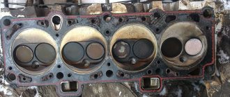
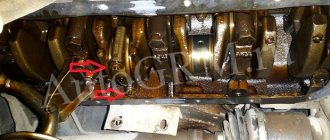
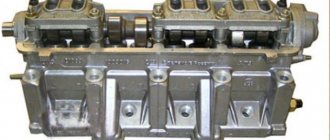
Traces of burnout of the cylinder head gasket on the cylinder block of a VAZ 2107
You also cannot tighten the cylinder head cover - this can damage it. Either cracks will appear in it immediately, or tension will arise, which will lead to this in the future. Also common is bolt rupture and thread stripping.
If you tighten the bolts in one place and not tighten them in another, the cylinder head of a VAZ-2107 car or its cover may warp. This will result in gaps that the gasket cannot compensate for. The result is the same as with loose bolts.
Lada 2107 2006, 74 l. With. — self-repair
Comments 2
Participate in the discussion can only registered users.
13.5 is normal, I think, otherwise antifreeze constantly leaks through the gasket if you tighten it loosely, either they started making such gaskets, or the bolts. Well, the main thing is not to overtighten, otherwise the cylinder walls will bulge a little inward, over time the hone will wear off and there will be a little oil starvation, Yes, and it’s harder for the piston to run in. Unless, of course, the block was sharpened with a false head.
Somewhere I came across the answer to this question. It seems on some nivoforum. They wrote there that the “old style” bolts with a 19mm wrench are tightened using the first method, and the 12mm bolts with the second method. I came to a conclusion similar to yours)
“>
Tightening torques for the VAZ-2107 block head on carburetor and injection engines
For the most part, the “seven” was equipped with carburetor engines of various modifications. Moreover, the most common version was a 1.5 liter engine with 77 hp. Although modifications of 1.3, 1.4 and 1.6 liters were also produced. There is no fundamental difference in the tightening torque of the cylinder head of the VAZ 2107 injector and carburetor.
The procedure for tightening the cylinder head bolts on a VAZ 2107 engine
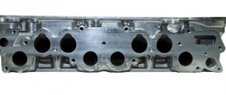
The cylinder head of an injection engine differs structurally only in the enlarged “windows” of the intake manifold channels, because the injector needs a little more air than the carburetor. But the tightening force of the VAZ-2107 cylinder head for such engines will be the same.
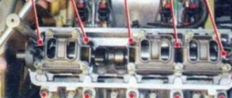
The instruction manual for the VAZ Seven contains clear data. First, the tightening order is important (see picture). Secondly, first you tighten the bolts by hand, and then tighten bolts No. 1-10 in two stages with the force indicated in the table (in newton and kilogram per meter). Bolt No. 11 is reached last, in one approach, with a force of 3.8 kgf/m.
| Tightening stage | Rated torque, Nm (kgf/m) | Minimum, N m (kgf/m) | Maximum, N m (kgf/m) |
| Preliminary | 39,2 (4,0) | 33,3 (3,4) | 41,16 (4,2) |
| Final | 112,7 (11,5) | 95,94 (9,79) | 118,38 (12,08) |
Attention! The VAZ-2107 cylinder head is tightened only with a torque wrench. Only in this way can a certain effort be strictly observed. Yes, you can easily find reviews “I do without a torque wrench, I always twist with a regular one,” but tightening by feel will never give you the accuracy you need. We wrote above about the consequences of an insufficiently tightened or overtightened cylinder head cover.
Tightening the cylinder head of the VAZ 2107 - second option
On some newer “sevens”, not ordinary M12x120x1.25 bolts were used to fasten the cylinder head, but torsion bar bolts - M12x115x1.25. Therefore, in addition to the first option of the sequence and degree of tightening, there is another option with data on the tightening force of the VAZ-2107 cylinder head. The process itself looks like this:
- Stage 1. Tightening the bolts to a torque of 2.0 kgf/m.
- Stage 2. Second tightening with a torque of 7.5-8.5 kgf/m.
- Stage 3. Turn each bolt 90 degrees.
- Stage 4. One more turn of all bolts by 90°.
- Stage 5. Tighten bolt No. 11 with a force of 3.8 kgf/m.
How to tighten correctly?
You can tighten the bolts with the help of specialists or yourself. If you have never encountered the need to perform this task before, then below we will look at how tightly you should tighten the screws and in what sequence you should do it.
Be sure to strictly observe the tightening torque, since if the head bolts are overtightened, this will lead to cracks and damage to the cylinder head. If this happens, the car owner will have to carry out major repairs to the unit. The working surface of the hole, as well as the threaded connection of the screw, must be as clean as possible. A wire brush can be used to clean the cylinders. If during the task you find “blind” holes for the head screws, use a cleaning lubricant carefully. If the volume of the substance is greater than required, it will be difficult to install the pin all the way.
Before tightening, it is necessary to visually diagnose the condition of the bolts. If the fastening elements are damaged or worn out, their quality is generally low, then it is better not to tighten them with these screws; it is recommended to replace them with new ones.
It is recommended to lubricate the threads of new bolts with a small amount of engine oil or another type of lubricant.
Tools and materials
To tighten the cylinder head, prepare only one tool - a torque wrench, which will allow you to determine the tightening force of the screws. It is best to purchase a key in a specialized store or rent it at a service station, since this tool can only be used for tightening and tightening. Using a regular wrench will not allow you to determine how many kilograms the tightening force is.
When purchasing bolts, it is recommended to give preference to branded parts. Be sure to look at the threaded part - it must be intact, without damage or defects; if any, the fasteners are replaced.
Channel “Engine Repair! And interesting!” published a video that describes all the nuances of the stretching process.
Algorithm of actions
The order and strength required when pulling the cylinder head bolts is as follows:
- In accordance with the diagram below, tighten all bolts using a torque wrench. The tightening torque on the first round of tightening the fasteners will be about 3.5 - 4.1 kgf/m. First, the bolts are tightened, which are located in the center of the block head - top and bottom. After this, the two upper and lower fasteners are screwed in, installed on the side of the screws located in the center. Then the two outer bolts are tightened. Please note that you need to tighten the left pins first, and then the right ones. Screw number 11, located at the bottom left, does not need to be touched.
- This is the first stretch circle. At the second stage, the bolts are tightened in a similar order. Only the force with which the fastening elements are tensioned by the tool will be 10.5 - 11.5 kgf/m.
- At the third stage, the bolt is tensioned, which is marked with number 11 in the diagram. The tightening force of this screw should be 3.5 - 4.0 kgf/m.
Different bolts and tightening degree of the VAZ-2107 cylinder head. What is the difference
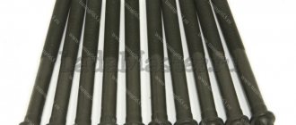
The “classic” was originally equipped from the factory with ordinary M12x120x1.25 bolts for a 19mm head. Their original catalog number was 2101-1003271 or 21213-1003271. The second number suggests that such bolts were also used on the VAZ-21213 Niva, which is why they are also called “Niva bolts”. Another colloquial name is “penny”. But most often they are simply identified as “cylinder head bolts for an old-style classic.”
On VAZ-2108 and VAZ-2109 cars, torsion bolts of a new type began to be used, which are also suitable for the “classics” - M12x115x1.25. They were unscrewed and tightened with a 12mm hexagon. It is noteworthy that AvtoVAZ’s catalog number remained the same, 21213-1003271. And it is the bolts of the new type that are sold in the original packaging. Their difference is that they “stretch” - and if correctly, they undergo elastic deformation. Actually, this is why you need to turn it twice by 90 degrees.
Old style cylinder head bolt
New sample cylinder head torsion bolt
Pay attention to the length of these bolts, encoded in the markings. 5mm difference with regular bolts. It is by these 5 millimeters that the bolt is deformed, completely filling the internal thread.
What is the difference between these bolts, other than the first ones are not sold in the original packaging and different bolts require different torque patterns? Classic bolts can be reused many times if their condition allows it. But on the other hand, you need to remember to do preventive tightening of the cylinder head bolts. About once a year, or more often, you will have to check the tightening torque of all the head bolts of your VAZ-2107 and tighten them if necessary.
The new type bolts do not require such a procedure, because due to elastic deformation they provide constant pressure on the cylinder head cover. But such bolts are disposable. When disassembling the cylinder head, you will have to buy a set of new ones. And unscrewing such bolts can be complicated by the fact that bolts tightened without a torque wrench can break.
Judging by the reviews of car owners, very often they can be unscrewed only by welding the nuts to 19. Therefore, many try to find old-style bolts, which are less troublesome.
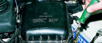
Start of work
The very first step is to remove the air filter. Of course, on a carburetor engine it is somewhat easier to remove it. If you have an injector, you will have to tinker with its rubber fasteners. But the essence remains the same - it is necessary to disassemble the fuel system completely to get to the cylinder head. But we will look at the example of not an injection, but a carburetor seven. Still, there are many more classic cars with such a power system.
It is advisable to dismantle the carburetor, since if you remove the head along with it, you can accidentally damage it. On all classic series cars, the carburetor is removed in the same way. This procedure is quite simple, but it will take some time. Now you can unscrew the nut securing the distributor and remove the distributor along with the wires. Getting closer to the engine, all that’s left to do is drain the antifreeze from the system.
And then turn off all the pipes that you see. After this, it will be possible to dismantle the cylinder head cover. It is secured with nuts and shaped washers. Don't lose them during repairs. That's all, the preparation is complete, you can begin the most difficult part - dismantling and installing the cylinder head.
Torque Tips and Common Mistakes
- Do not jerk the cylinder head bolts. Tightening should be done smoothly.
- When installing cylinder head bolts (especially old ones), carefully examine their condition - there should be no damage to the threads. Exactly the same as inside the installation site.
- If necessary, the part must be cleaned of contamination.
- It is better to lubricate the threads with oil, but pouring them into the mounting holes is not recommended. If the wells are blind, then the lubricant must be applied very carefully. Fluids do not compress and excess lubrication will prevent you from tightening the bolt all the way.
- Failure to use a torque wrench may result in inaccurate tightening torques and incorrect gasket operation or damage to the cylinder head.
Removing the head
Installing the ignition of a VAZ 2107 injector by marks
Now we have to remove the cylinder head. To do this, take a powerful wrench in your hands and unscrew the 10 mounting bolts in a circle. An important point is that the 11th bolt is installed on the ebb of the head. It is small in size. We also extract it. Carefully pry up the element and take it out.
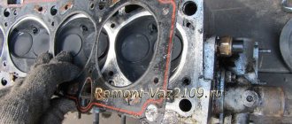
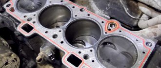
So, before us is the opened head of the block. All we have to do is remove the old gasket and install a new one in its place
It is important to thoroughly clean the contact surface. If this is not done, oil will leak through small channels into the adjacent chamber and mix with antifreeze.
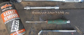
Experts recommend using a special spray.
Pay attention to such a moment as tightening the cylinder head. A lot will depend on this operation
If you do not apply force, the gasket will burn out and the engine may boil. Therefore, experts recommend using a torque wrench (see figure below).
Tightening torques for threaded connections on the VAZ 2107
| Detail | Thread | Tightening torque, N.m (kgf.m) |
| ENGINE | ||
| Main bearing cap bolt | M1×1.25 | 68,31–84,38 (6,97–8,61) |
| Oil sump bolt | M6 | 5,10–8,20 (0,50–0,85) |
| Breather cover mounting stud | M8 | 12,7–20,6 (1,3–2,1) |
| Breather cover nut | M8 | 12,7–20,6 (1,3–2,1) |
| Cylinder head bolt: | ||
| M12×1.25 | 33,3–41,16 (3,4–4,2) |
| M12×1.25 | 95,94–118,38 (9,79–12,08) |
| Cylinder head bolt | M8 | 36,67–39,1 (3,13–3,99) |
| Nut securing inlet and outlet pipelines | M8 | 20,87–25,77 (2,13–2,6) |
| Connecting rod cap bolt nut | M9×1 | 43,32–53,51 (4,42–5,4) |
| Flywheel bolt | M10×1.25 | 60,96–87,42 (6,22–8,92) |
| Chain tensioner shoe bolt | M10×1.25 | 41,2–51,0 (4,2–5,2) |
| Camshaft bearing housing stud nut | M8 | 18,33–22,6 (1,87–2,3) |
| Camshaft sprocket bolt | M10×1.25 | 41,2–51,0 (4,2–5,2) |
| Oil pump drive shaft sprocket bolt | M10×1.25 | 41,2–51,0 (4,2–5,2) |
| Valve adjusting bolt nut | M12×1.25 | 43,3–53,5 (4,42–5,46) |
| Valve adjusting bolt bushing | M18×1.5 | 83,3–102,9 (8,5–10,5) |
| Spark plug | M14×1.25 | 30,67–39,0 (3,13–3.99) |
| Coolant pump mounting bolt | M8 | 21,66–26,75 (2,21–2,73) |
| Nut of the stud securing the exhaust pipe of the cooling jacket | M8 | 15,97–22,64 (1,63–2,31) |
| Crankshaft ratchet | M20×1.5 | 101,3–125,6 (10,3–12,8) |
| Generator bracket mounting bolt | M10x1.25 | 44,1–64,7 (4,5–6,6) |
| Generator mounting bracket nut | M10x1.25 | 28,63–45,27 (2,86–4,62) |
| Nut of the bolt securing the generator to the bracket | M12x1.25 | 58,3–72,0(5,95–7,35) |
| Nut securing the mounting plate to the generator | M10×1.25 | 28,08–45,3 (2,86–4,62) |
| Nut securing the cushion to the front support bracket | M10x1.25 | 21,6–35,0 (2,21–3,57) |
| Nut securing the front engine mount to the cross member | M10x1.25 | 27,4–34,0 (2,8–3,46) |
| Nut securing the plate to the pillow | M6 | 5,7–9,2 (0,58–0,94) |
| Nut securing the rear engine mount to the body | M8 | 15,0–18,6 (1,53–1,9) |
| Nut securing the rear support to the gearbox | M8 | 23,3–28,8 (2,38–2,94) |
| Nut of the bolt securing the rear support to the cross member | M8 | 15,9–25,7 (1,62–2,62) |
| Electric fan sensor | M22×1.5 | 40,0–49,4 (4,08–5,04) |
| CLUTCH | ||
| Clutch bolt | M8 | 19,1–30,9 (1,95–3,15) |
| Clutch and brake pedal mounting bolt nut | M12×1.25 | 12,7–20,6 (1,3–2,1) |
| Clutch and brake master cylinder nuts | M8 | 9,8–15,7 (1,0–1,6) |
| Connection of hydraulic brake pipes | M10 | 14,7–18,6 (1,5–1,9) |
| Connection of hydraulic clutch tubes | M12 | 24,5–31,4 (2,5–3,2) |
| TRANSMISSION | ||
| Reversing light switch | M14×1.5 | 28,4–45,1 (2,9–4,6) |
| Bolts securing the clutch housing to the engine | M12×1.25 | 53,9–87,2 (5,5–8,9) |
| Nut securing the clutch housing to the gearbox | M10×1.25 | 31,8–51,4 (3,25–5,25) |
| Nut securing the clutch housing to the gearbox | M8 | 15,7–25,5 (1,6–2,6) |
| Bolt securing the rod clamp cover | M8 | 15,7–25,5 (1,6–2,6) |
| Rear cover fastening nut | M8 | 15,7–25,5 (1,6–2,6) |
| Nut of the rear end of the driven shaft | M20×1 | 66,6–82,3 (6,8–8,4) |
| Intermediate Shaft Bearing Clamp Washer Bolt | M12×1.25 | 79,4–98,0 (8,1–10,0) |
| Bolt securing the fork to the gearshift rod | M6 | 11,7–18,6 (1,2–1,9) |
| CARDAN TRANSMISSION | ||
| Front propeller shaft fork nut | M16×1.5 | 79,4–98,0 (8,1–10,0) |
| Nuts of bolts securing the elastic coupling | M12×1.25 | 57,8–71,5 (55,9–7,3) |
| Nut of the bolt securing the propeller shaft flange to the gearbox flange | M8 | 27,4–34,3 (2,8–3,5) |
| REAR AXLE | ||
| Gearbox mounting bolt | M8 | 35,0–43,2 (3,57–4,41) |
| Differential bearing cover bolt | M10×1.25 | 43,3–53,5 (4,42–5,46) |
| Driven gear bolt | M10×1.25 | 83,3–102,9 (8,5–10,5) |
| Nut securing the flange to the drive gear | see rear axle | |
| Nut for the mounting plate of the axle shaft bearing and brake shield | M10×1.25 | 41,6–51,4 (4,25–5.25) |
| STEERING | ||
| Steering housing mounting bolt nut | M10×1.25 | 33,3–41,2 (3,4–4,2) |
| Nut of a bolt of fastening of a bracket of the pendulum arm | M10×1.25 | 33,3–41,2 (3,4–4,2) |
| Steering linkage ball pin nut | M14×1.5 | 42,1–53,0 (4,3–5,4) |
| Bolt securing the steering shaft to the worm shaft | M8 | 22,5–27,4 (2,3–2,8) |
| Steering wheel nut | M16×1.5 | 31,4–51,0 (3,2–5,2) |
| Nut securing the steering shaft bracket and ignition switch | M8 | 15,0–18,6 (1,53–1,9) |
| Bipod fastening nut | M20×1.5 | 199,9–247,0 (20,4–25,2) |
| Pendulum arm axle nut | M14×1.5 | 63,7–102,9 (6,5–10,5) |
| FRONT SUSPENSION | ||
| Bolt securing the cross member to the body side member | M12×1.25 | 78,4–98,0 (8,0–10,0) |
| Nut of the lower bolts securing the cross member to the body side member | M12×1.25 | 66,6–82,3 (6,8–8,4) |
| Nut of the lower arm axle mounting bolt | M12×1.25 | 66,6–82,3 (6,8–8,4) |
| Lower arm axle nut | M14×1.5 | 63,7–102,9 (6,5–10,5) |
| Upper arm axle nut | M14×1.5 | 57,3–92,1 (5,85–9,4) |
| Nut securing the upper end of the shock absorber | M10×1.25 | 27,4–34,0 (2,8–3,46) |
| Nut securing the lower end of the shock absorber | M10×1.25 | 50,0–61,7 (5,1–6,3) |
| Front wheel hub bearing nut | M18×1.5 | see Front suspension |
| Bolt securing the caliper to the bracket | M10×1.25 | 29,1–36,0 (2,97–3,67) |
| Anti-roll bar mounting nut | M8 | 15,0–18,6 (1,53–1,9) |
| Nut securing ball pins to steering knuckle | M14×1.5 | 83,3–102,9 (8,5–10,5) |
| Wheel bolt | M12×1.25 | 58,8–72,0 (6,0–7,35) |
| Steering knuckle bolt nut | M10×1.25 | 50,0–61,7 (5,1–6,3) |
| REAR SUSPENSION | ||
| Shock absorber mounting nuts | M12×1.25 | 38,2–61,7 (3,9–6,3) |
| Nuts of bolts for fastening transverse and longitudinal rods | M12×1.25 | 66.6–82,3 (6,8–8,4) |
Gearbox assembly
Assembly of the VAZ 2105 gearbox
Rear axle gear parts
Reliable operation of the gearbox is ensured by strict adherence to the following assembly and adjustment procedures.
Differential assembly
Installing and adjusting the drive gear
Final drive gears
The correct position of the drive gear relative to the driven gear is ensured by selecting the thickness of the adjusting ring installed between the thrust end of the drive gear and the inner ring of the rear bearing.
Select the adjusting ring using mandrel A.70184 and fixture A.95690 with indicator.
Adjusting the drive Installing the differential box
Checking the preload of the differential box bearings using tool A.95688/R
Checking the lateral clearance in the meshing of the main gears using tool A.95688/R
Video about “Assembling the gearbox” for VAZ 2105
VAZ (2 parts). Rear axle gearbox repair - Part 1 How to replace the rear axle gearbox, replacement tips. Dismantling the steering gear assembly of VAZ.
The nuances of replacing the gasket
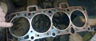
Some resources advise studying the gasket to find out what kind of damage has occurred on it. This, in fact, is just a waste of time, because the specified element cannot be repaired. Just throw away the old one and install a new one.
It is necessary to stop at the last point. After removing the old sealing element, thoroughly clean the surface underneath it. If necessary, treat with fine sandpaper - only on an ideal, even base does it make sense to install the purchased gasket. The slightest bulge, even with proper tightening, will cause a leak.
Before replacing the head, make sure that all the valves of your VAZ car are in good working order.
Pay special attention to the oil seals - it is better to replace worn ones immediately. If a new type of gasket is used on the machine, then it is mounted on sealant - apply it around the perimeter on both sides
Step by step guide
VAZ 2107 cylinder head in the engine compartment Many problems can be resolved after tightening the bolts, but if this does not help, then a major overhaul of this unit may be necessary, which involves removing not only the cylinder head, but also other parts of the block. Some parts may need to be replaced, such as gaskets, valve stem seals and valve guides.
Tools
To work we will need the following tools:
- a set of keys;
- micrometer;
Micrometer - flushing liquid;
- pliers;
- hammer;
- mandrels for removing and installing valves and caps;
- torque wrench;
Torque wrench - tiles (preferably the spiral is closed);
- desiccant.
Valve desiccant
Before starting repair work on the cylinder head, it must first be removed and cleaned of dirt.
Preparatory work and head removal
- The first step is to drain the coolant from the engine.
- We remove the carburetor.
- Having disconnected the pipes and hoses, remove the air barrier.
Disconnect the hoses and pipes - Remove the head cover.
- We align the marks on the crankshaft pulley with the mark on the camshaft drive and the marks on the camshaft pulley with the mark on its housing as shown in the photo.
Aligning marks - By disconnecting the camshaft lock washer, loosen the chain tension.
- Having torn off the bolt, remove the sprocket.
- Unscrew the fastenings.
- We remove the camshaft with the housing.
Camshaft - Having previously made marks using a marker, remove the rockers.
Removing rockers - Disconnect the wires.
- We remove the pipe and unscrew the bolts securing the cylinder head to the block.
- We remove the head.
- We inspect its condition and clean it of dirt.
Inspection of the head condition
This video shows the process of removing the cylinder head.
Checking status
Now it's time to dry out the valves. This is done with a special device. If chips, cracks, and rust are not visible, we conduct a further inspection. We evaluate the condition of the saddles, the repair of which is recommended every two hundred thousand kilometers.
Changing guide bushings
We inspect the guide bushings; if they are in unsatisfactory condition, they must be replaced.
A special tool is used to remove them. If you don’t have this on hand, you can get by with pliers and a clamp. After removing the bushings, we measure their diameter. We buy similar ones, the size of which is 0.05-0.07 millimeters larger than the ones being replaced.
The guides are pressed in using a mandrel, an electric stove, a hammer and lubricant.
- We place the head on a stand at the edges.
- We place the electrical device under the place of work.
- We wait until the metal heats up to about one hundred degrees (so that it expands).
- Now you need to properly lubricate the bushing with grease.
- Having removed it from the holders, we drive in new guides.
- When all eight are replaced, we wait for the cylinder head to cool down.
- The valves should not dangle and move freely, there should not be any jamming.
Checking the tightness of the head
Checking tightness To ensure a tight fit of the valves to the seats, do the following. Using lapping paste, lubricate the valve and insert it into the head. There are several techniques for rotating it, here are some of them:
- using a hose tightly placed on the part;
- using a device very similar to a corkscrew.
The main sign of good valve lapping will be a specific matte surface of the seat in the place where it contacts the part.
The tightness of the head can be checked by pouring kerosene into the collectors; you can also use gasoline. If done correctly, there should be no leaks for the first five to seven minutes.
When assembling the head, be sure to pay attention to the correct tightening of the bolts. It must be carried out strictly according to the scheme
In case of incorrect broaching, distortions may appear and, as a result, all your previous work will be crossed out. If you have any questions, watch the video.
Need for replacement
There are few reasons for replacement and some of them require immediate intervention, while others not so much, that is, the vehicle can be used, albeit in a gentle manner.
Reasons for replacement:
- Damage to the gasket in the area of the cooling system channel and the drainage channel of the lubrication system. When this happens, the coolant ends up in the oil pan and mixes with the lubricant. The result is a mixture with a brownish tint. This can be detected by checking the lubricant level in the power unit on the dipstick. This malfunction is also indicated by a decrease in the coolant level in the radiator. If you do not intervene in time, the consequences can be catastrophic, including the destruction of the power unit.
- Damage to the gasket in the area of the cooling system channel and cylinder. This may occur due to a poor quality gasket or an incorrectly installed head.
- Burnout in the cylinder area. This malfunction is detected and diagnosed by a decrease in compression in the cylinders and unstable engine operation.
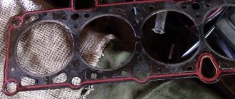
Burnout between cylinders
- Destruction of the gasket. If coolant begins to leak through the gasket and all efforts to tighten the cylinder head do not bring any results, then an urgent replacement is necessary.