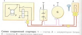
Checking the field winding for interturn short circuit
The interturn short circuit causes an increase in the excitation current. Due to overheating of the winding, the insulation is destroyed and even more turns are shorted together. An increase in excitation current may lead to failure of the voltage regulator. This malfunction is determined by comparing the measured field winding resistance with the specifications. If the winding resistance has decreased, then it is rewound or replaced.
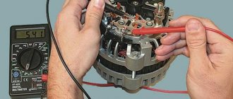
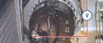
The interturn short circuit in the excitation winding coil is determined by measuring the resistance of the excitation coil using an ohmmeter available at stands E211, 532-2M, 532-M, etc., a separate portable ohmmeter (see Fig. 14, c), or according to the readings of an ammeter and voltmeter when the winding is powered from a battery (see Fig. 14, d). The fuse protects the ammeter and battery in the event of an accidental short circuit. Probes are connected to the rotor slip rings and by dividing the measured voltage by the current, the resistance is determined and compared with the technical specifications (see Table 2).
Rice. 14. Checking the field winding:
a—on a cliff; b—for short circuit with the shaft and pole; c - with an ohmmeter for open circuit and interturn short circuit; g — — connection of instruments for determining resistance.
Checking the stator winding for a break. Checking the stator winding for a break is carried out using a test lamp or an ohmmeter. The lamp and power source are alternately connected to the ends of the two phases according to the diagram in Fig. 15, a. If there is a break in one of the coils, the lamp will not light. An ohmmeter connected to this phase will show “infinity.” When connected to the other two phases, it will show the resistance of those two phases.
Interturn short circuit in the generator winding. How to detect. Advice from an auto electrician.
If the channel brings you real benefits, then support the project! The amount doesn't matter! CARD (SBERBANK)…
Interturn short circuit in the stator winding of the generator.
If the channel brings you real benefits, then support the project! The amount doesn't matter! CARD (SBERBANK)…
Checking the stator winding for a short circuit with the core. If such a malfunction occurs, the power of the generator is significantly reduced or the generator does not work, and its heating increases. The battery is not charging. The test is carried out with a 220 V test lamp. The lamp is connected to the core and any winding terminal according to the diagram in Fig. 15, b. If there is a short circuit, the lamp will light up.
Checking the stator winding for interturn short circuit. Interturn short circuit in the stator winding coils is determined by measuring the resistance of the phase coils with a separate ohmmeter (see Fig. 15, c), on stands E211, 532-2M, 532-M and others, or according to the diagram shown on rice. 15, g. If the resistance of two windings (measured or calculated) is less than that indicated in the table. 2, then the stator winding has an interturn short circuit. This fault can be detected using the stator winding zero point. To do this, it is necessary to measure or calculate the resistance of each phase separately and, comparing the resistance
Rice. 15. Checking the stator winding:
a - on a cliff; b - for short circuit with the core; c - for interturn short circuit and open circuit
ohmmeter; d - connection of instruments to determine the resistance of the stator winding
all three phases, determine which of them has an interturn short circuit. A phase winding that has an interturn short circuit will have less resistance than others. The defective winding is replaced.
The serviceability of the stator windings can be checked on test benches for phase symmetry. During this test, the alternating voltage is measured between the phases of the stator winding up to the rectifier unit at the same (constant) generator rotor speed. If the voltage induced (induced) in the stator windings is not the same, then this indicates a malfunction of the stator winding.
What components and parts are checked using a multimeter?
This operation involves diagnosing the electrical part, and checking the following parts:
- Voltage measurements are taken at the generator output;
- the rotor excitation winding is checked for open circuit or short circuit to the housing;
- checking the stator windings for breakdown and open circuit;
- carry out fault detection of the diode bridge, capacitor;
- faults in the voltage regulator and brushes are detected;
Performing each of the listed operations requires special knowledge and skill to carry out measurements, so each test should be considered in more detail.
Output voltage level measurement
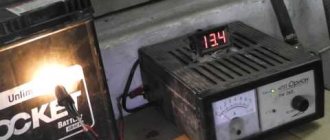
For each individual unit this value will be different. Let's take a closer look at checking a car generator. Set the voltage measurement mode on the multimeter scale. First you need to check the voltage with the engine turned off. To do this, measure the voltage value at the battery terminals. We connect the red probe to the positive terminal, and attach the black one to the minus terminal. A charged, serviceable battery will produce a value of up to 12.8 V. We start the engine. Then we take a measurement. Now this value should be no more than 14.8 V, but no less than 13.5 V. If the voltage level is higher or lower, the generator is faulty.
Common breakdowns
Generator faults can be electrical or mechanical. These include:
- loss of functionality of the voltage regulator;
- breakdown of the rectifier unit (diode bridge);
- short circuit of stator windings;
- current short circuit in the rotor winding;
- wear of bearings and brushes.
Read also: Goniometer instruments of the ancient Babylonians, sectants and octants
Voltage regulator
The purpose of this unit is to normalize the voltage before feeding it into the automotive electrical circuit. You can check the serviceability of the regulator by checking the voltage that it supplies to the battery terminals. This indicator depends on the model and brand of the vehicle and varies between 13.5-15.5 V. Therefore, you should find out in advance what voltage your particular type of regulator produces. This can be done by studying the manual for using the machine. For example, you can take a VAZ 2107 or 2110 car, since these vehicles have the most typical faults associated with the integral and relays.
Using a Multimeter
To check the VAZ 2110 generator with a multimeter, you need to switch the device to voltmeter mode. Then you need to connect its probes to the battery terminals. The most important thing is to observe the polarity and turn off the car engine. The voltage normally varies from 12 to 12.8 V. Next, the procedure should be repeated, but with the engine running. The voltage readings should rise to 13.5-15.5 V. Lower and higher voltage values indicate a malfunction of the generator.
Checking the generator without removing it from the car
A bridge of diodes performs the functions of a kind of alternating current converter. It contains three negative and three positive diodes.
Before checking the bridge, you need to disconnect all the wires coming from it and from the voltage regulator. You also need to remove the ground anchor from the battery in advance. First you need to check the rectifier for short circuits. We activate the ohmmeter mode on the multimeter and connect the red (positive) probe to the positive contact of the diode bridge, and the negative probe to the surface of the housing of the generator itself. If the rectifier is fully operational, then the readings of the measuring device will go to infinity. In other cases, the rectifier will be inoperative.
Testing of stator and rotor windings
A common breakdown of a car generator is a short circuit in the windings. It occurs when current surges are too intense, brushes wear out and liquid gets in.
So, you need to remove the rotor and find a pair of slip rings on its structure that will need to be ringed. Having started the ohmmeter mode on the multimeter, we connect the probes to these rings. Normal resistance is 2-6 ohms. If you get large values, then there is a loss of contact between the slip rings. If the device shows lower values, then an interturn short circuit has occurred.
The starter has several windings at once. They need to be checked separately. However, first you need to disconnect the wires that connect the diode bridge and the winding terminals.
Then you should measure the resistance between zero and the terminals of the windings. The normal value is no less than 0.3 Ohm.
Wear of brushes and bearings
If you have already disassembled the generator, then it is advisable to check the condition of the brushes. They can wear out or break due to misalignment of the rotor shaft. If the brushes are damaged, they should be replaced with new ones.
Inside a car alternator there are a pair of bearings. One is fixed on the rotor shaft, the other is in the center of the cover. The whistling and hum of the generator when the engine is running is a clear sign of bearing wear. In this case, the generator housing can become very hot. If you notice such signs, it is better to replace the bearings immediately, otherwise you may encounter more serious problems.
You can check the bearing by removing the belt from the generator and trying to rotate its shaft with your own hand. If the part rotates freely and easily, then everything is in order. If it is difficult to rotate the rotor, then you should not delay replacing the bearings.
How to check the generator for performance? Self-check and repair of the generator
A generator is a typical electrical station that provides energy to all engine systems: power, cooling, ignition, so its failure will inevitably lead to other malfunctions. To prevent breakdowns, you need to systematically diagnose it, and if problems cannot be avoided, repair it immediately.
In this article we will talk about how to check the generator for performance without resorting to the help of professionals. But before that, let's look at the symptoms of its possible defects.
Checking the rotor winding
To perform this operation, it is necessary to dismantle and disassemble the unit. When performing a self-test, do not forget to set the device to the circuit resistance measurement mode. Additionally, a value of no higher than 200 Ohm is set. These routine maintenance works are carried out in 2 stages:
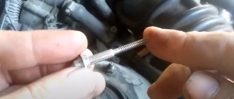
- Measuring the resistance value of the rotor windings. To do this, we attach the probes to the rings of the moving part of the engine and determine the value. This will make it possible to determine the probability of a winding circuit break at a value above 5 ohms. If the device shows less than 1.9 ohms, a turn short circuit has occurred. Most often, the chain breaks at the junction of the rotor winding lead to the ring. You can determine the defect by moving the wire with a probe at the soldering points, as well as by detecting darkened and crumbling wire insulation. In the event of a break or short circuit (short circuit), the wires become very hot, so the breakdown can be detected by visual inspection.
- A circuit test is performed to detect a short circuit to the frame. We position the generator rotor conveniently for operation. Then we bring one probe to the rotor shaft, and attach the second to any ring. If the winding is working properly, the resistance reading will go off scale. If it shows low resistance, this part should be sent for rewinding. When rewinding the rotor, it is important to maintain perfect balancing.
Checking the stator windings
Checking the stator begins with a visual inspection. We pay attention to external damage to the housing and insulation, and places where wires are burned during a short circuit.
The faulty unit should be rewound or replaced. If the external integrity of the wires is established, we begin to investigate using a tester.
Advice! Before starting work, you should make sure that the unit is disconnected from the network and that there is no contact between the leads of the stator windings.
When performing work to check the normal state of the node, we make sure:
Voltage Regulator Troubleshooting
Remove and disconnect the wires from the part. We inspect the condition of the brushes. They should not have significant defects or chips. In the guide channels of the brush holder, the generator brushes must move freely. If they protrude beyond the edge by less than 5 mm, the generator regulator should be changed.
The test is carried out using batteries and a 12-volt light bulb. The voltage of the second power source must be at least 15 V, so we connect the batteries in series to the car battery and adjust the value to the desired value. We attach the plus from the 1st power source to the output contact, and the minus to ground.
The light bulb is installed between the brushes. When connecting a 16 V source, it should not light up. With a weaker battery, it lights up. If proper combustion is not observed, the regulator should be replaced.
Replacing brushes on VAZ 2110-VAZ 2112
Note! There are two replacement methods:
the first is to remove the generator from the car and replace the brushes (convenient, but takes more time, the procedure is described in detail in the publication: “Replacing the generator in a car”);
the second is to disconnect the minus terminal from the battery (read in paragraph 1 of the article: “Replacing the battery in a car”) and doing all the work on the installed generator on the car.
Perhaps the second option is not very convenient, however, if you do everything correctly, you will save a little time, and it is not difficult to remove the brushes.
1. To change the brushes, first press out the three latches on the sides of the generator that secure the cover to it. By removing the cover (see small photo), you have access to the voltage regulator. It has two fastening screws (indicated by blue arrows), unscrew them and, by pulling the regulator, disconnect them and thereby remove them completely from the generator.
Note! You can completely change the regulator with brushes, but if this is not possible (for various reasons, for example, financial difficulties), replace separately the brushes attached to the regulator by soldering. More precisely, their wires are soldered to the terminals of the regulator - take a soldering iron and unsolder the wires coming from the brushes. Then remove them from the regulator and install new ones in the same way using soldering. We have attached a video for clarity.
2. Having removed the regulator, inspect the condition of the brushes: the length must be at least 5 mm (photo 1), otherwise replacement is necessary. We recommend checking the regulator as follows: connect a 12 Volt test lamp, as shown in Diagram 2 (to the brushes), and apply a voltage of 12 Volts. The battery may give in, run some thin wires from it “+” to the terminal, and “-” to ground. The lamp should light up. Perform a similar operation with a current not of 12 V, but of 15-16 V. A dead lamp means: everything is in order with the regulator and it does not need to be replaced.
Additional video We have attached a video
Checking the diode bridge and capacitor
The purpose of this unit is to prevent the passage of electricity to the generator. It must direct it from the generator to the consumer. In this case, any deviation is a malfunction of the diode bridge. To check, we dismantle it and solder the terminals on the generator. We set the device to “ring”.
To check the power diode, we bring the black probe to the bridge plate, and attach the red probe to the output. If the multimeter reading is 400-800 Ohm, the diode is working, other numbers require replacing the diode or bridge.
When checking the auxiliary diode, the operation is performed in a similar way. But when the probes are swapped, the device should show a resistance value tending to infinity.
To detect a faulty capacitor, you can check it using the “old-fashioned method”. To do this, you need to apply voltage to it for a short time. It should charge. When its contacts close, a spark should break between them. This means that the capacitor is working.
When checking a polar capacitor, you need to remove the remaining charge. Then, set the resistance measurement on the scale. The contacts must be attached with correct polarity. When measuring a working part, the resistance gradually increases. Otherwise, when the screen shows 0, it should be replaced.
If a non-polar capacitor is being tested, the value scale is set to MOhm. We place the probes on the contacts regardless of polarity. Then, you need to measure the resistance value. If the number on the screen is less than 2 ohms, this is a faulty part.
In conclusion, it is necessary to recall that all measurements when checking the functionality of the generator using a multimeter are carried out by measuring the value of the electric current resistance. Only to measure the voltage at the output of the generator, the device is configured to measure this value. Any beginner can test a generator with a multimeter. You just need to work with full responsibility and follow the instructions.
Fault diagnosis
Now that we have the brush holder with the regulator and the capacitor in our hands, replacing the generator brushes on the VAZ 2112 is carried out together with the brush holder and the relay regulator, but we need to make sure that the cause of the malfunction lies here, so we begin to look for the fault. So:
- It is necessary to clean the contact on the brush holder with sandpaper, they are marked in the photo below; poor contact in this place can also cause poor operation of the electric generator
Clean the contact highlighted in red
- We check the serviceability of the relay - voltage regulator, to do this we connect a 12 Volt light bulb to the brushes
- We apply a voltage of 12 Volts, “+” goes to the terminal, and “–” goes to the ground of the brush holder
- The indicator light should light up
We connect the light bulb to the brushes and apply 12 volts to the contacts of the relay-regulator
- Next, we apply a higher voltage: 15–16 Volts - the light should go out
- When the light is on or does not light up in both cases, this means that the regulator is faulty and needs to be replaced along with the brush holder
- We check the ease of movement of the brushes in the brush holder body and the height of their protrusion
- If they protrude from the body by less than 5 millimeters, replacement is needed; the brushes of the VAZ 2112 generator are changed along with the relay - voltage regulator and brush holder
Required brush height
- If you find chips and cracks on the brushes, then replace the generator brushes on the VAZ 2112
- To change the brushes alone, we pull out the holder from the relay housing - voltage regulator, to do this we press on terminal “B”
- Before installing the voltage regulator with new brushes in place, blow the installation socket on the generator from dust and wipe off oil
This completes the replacement of brushes on the generator for the VAZ 2112; we move on to the last small but important part - the capacitor (see Changing the capacitor (VAZ generator)).
Tip: When there is already wear on the slip rings of the electric generator, it is recommended to slightly grind down the contact corners on the brushes, so that the new brushes will fit more easily into the grooves of the worn slip rings
Capacitor functions and testing
If you have never dealt with capacitors, these instructions will help you:
- The capacitor is designed to protect all electronic equipment of the car from voltage pulses (jumps) appearing in the ignition system; it also reduces radio interference
- If the capacitor is damaged or its fastening on the electric generator is loosened (contact with the housing worsens), it sharply increases the interference of the radio receiver when the engine is running
Its serviceability can be checked using a megger or tester (with a scale of 1–10 Mega Ohms):
- We connect the probes of our tester to the terminals of the capacitor
- It should show infinity before connecting
- Resistance decreases only at the moment of connection, and then must return to infinity again
- This means the capacitor is working properly
- Otherwise, the capacitor must be replaced
Attention: The K73-58-4 capacitor is installed on the VAZ2112 electric generator. The marking is located on the side of the case. To avoid problems, it is not recommended to install a different type of capacitor.
- We screw the capacitor back, pay attention that it is important to accurately orient the capacitor relative to the special mounting protrusion located on the cover of the electric generator, otherwise the brush holder will not fall into place
- We connect the connector back to the brush holder (the bend of the output wire faces up), screw it back, and the brushes must fall onto the slip rings
- Snap the plastic cover, insert and screw the wires back
- If there is a spring washer on the “+” bolt under the nut, it must be removed; dirt and moisture often accumulate under it, which often leads to oxidation and deterioration of contacts
- We put the terminals on the battery
That’s all for the VAZ 2112 generator, replacing the brushes is over, if some points are not entirely clear to you, we recommend watching the video.
Add a commentAdd a comment We advise you to readInstructions for mounting the generator on a VAZ 2112 with your own handsReplacing the diode bridge of the VAZ 2110 generator on your ownReplacing the relay in the VAZ 2109 generator - couldn’t be easierVAZ 2112: generator faults and identifying them
The generator in the car design is responsible for supplying voltage to all components of the on-board network. It is a fairly reliable unit, but it requires maintenance from time to time to prevent serious breakdowns. One of the stages of service work is replacing brushes.
These stator elements, made of durable graphite, supply current to the rotating rotor of a car generator. Constant friction gradually wears out the brushes. It is not difficult to identify it - you will definitely notice the appearance of problems in the car's electrical supply system.
How to test a car alternator with a multimeter
Stable and correct operation of the car’s electronics largely depends on the serviceability of the generator. It provides power to all devices and also helps start the engine. In this regard, it is important to monitor its serviceability, and if necessary, know how to check a car generator with a multimeter.
This element is directly connected to the battery, which also often causes problems. And if it is necessary to connect new devices and various devices to the standard on-board network, you should check the serviceability of the generator, since it is the source of the standard current. In other words, this is one of those parts that needs to be checked regularly.
Main signs of generator malfunction
The following signs will indicate that the generator has failed or problems have arisen in its operation:
- constant lighting of the warning light in the form of a reddish battery on the dashboard, which indicates that the generator is not charging or is producing insufficient current;
- constantly discharging battery;
- interruptions in the operation of electrical equipment (lighting and alarm units, multimedia, heating and ventilation) while the engine is running;
- the appearance of a corresponding burnt aroma in the cabin (engine department);
- excess heating of the generator stator;
- rumble (rustle, whistle) of the generator.
Read also: What metals does zinc belong to?
The appearance of similar symptoms is a serious reason to conduct a diagnosis. To do this, it is absolutely not necessary to contact a service station, because you can completely check the generator for operability on your own, especially if you have even the slightest ability to use an auto tester. But first, let's talk about the main breakdowns.
Relay regulator
The relay regulator maintains the optimal voltage value in the standard electrical circuit. In fact, it is precisely this that prevents the voltage from increasing to critical values. To carry out the test, start the engine, connect the multimeter and set the “voltage measurement” value.
After this, it is necessary to measure the power supply of the on-board network directly at the battery terminals or at the contacts of the generator itself. The values should be between 14–14.2 V.
Then you need to press the accelerator and take the measurement again.
Note! The readings should not change by more than 0.5 V. Otherwise, this will indicate incorrect operation.
What is important to remember
When checking in this way, it is extremely important to be careful and follow safety precautions. If a would-be auto electrician confuses the plus of the battery with the minus, then as a result it may well fail. As a result, the “specialist” will be additionally “punished” with a ruble.
Also, do not touch bare areas of the wiring with your hands when the electrical circuit has already been assembled. Electric shocks themselves are quite unpleasant. And if you are very “lucky”, for example, to get hit while standing in a puddle in shoes that conduct electricity well, then the situation can generally turn out to be lethal. Therefore, if a car owner strongly doubts his technical abilities, it is better to entrust the diagnosis to specialists.
Subscribe to our Social networks
Diode bridge
The diode bridge consists of six separate diodes: half of them are positive, the other half are negative. It is necessary to select the “Dial” mode on the multimeter. After this, as soon as the contacts on the tester close, a soft beeping sound will be heard. You need to check in both directions. If a squeak is heard in both cases, then this indicates a breakdown of the diode. Therefore, it needs to be replaced.
We call the diode bridge
When the multimeter probes are positioned as in the following photos, the resistance should be infinite; if the probes are swapped, it should be within 700 Ohms.
Procedure for checking negative diodes
Checking the positive diodes
Now the auxiliary diodes
Procedure for checking negative diodes
Checking the positive diodes
Now the auxiliary diodes
Generator rotor
The rotor is a rod made of metal with an excitation winding. If you look at one of its ends, you can see special contact rings with sliding brushes.
Rotor check
First of all, it is necessary to remove the rod and conduct an external inspection of the winding, as well as the bearings. In some cases, the problem is damage. If everything is in order, then you should proceed to checking with a multimeter.
The device should be set to “Resistance measurement” mode. It should be checked between the slip rings. This value should not be too large - this indicates the serviceability and integrity of the winding.
Note! It is quite difficult to carry out detailed diagnostics of the rotor on your own, so if you suspect any problems, you should contact a car repair shop.
Brushes and slip rings
Rings and brushes can be checked visually, assessing their condition and serviceability. Check the protruding length of the brushes. It must be at least 4.5 mm. And the norm is 8-10 mm.
Also, the diameter of the slip rings must be at least 12.8 mm. and ideally 14.2-14.4. Worn rings can be replaced if you find them in a store. They are removed with a special puller, and the winding terminals are unsoldered. After installing new rings, they can be turned on a lathe to eliminate runout and sanded with fine sandpaper to eliminate burrs.
Hello everyone, in this post I will tell you in detail about replacing the slip rings and bearings of the generator. These parts don’t cost much, but after replacement we get an almost new one!
We will need: Front generator bearing 303, I purchased Vologda VBF (VPZ-23) - 90 rubles Rear generator bearing 202, I purchased Vologda VBF (VPZ-23) - 70 rubles Contact rings, also known as generator rotor collector - 100 rubles You also need to buy a new regulator voltage - 130r. I recommend or "Orbita", but I did not buy it, since the length of the brushes of the old regulator is still sufficient.
I also needed: Tension bar for generator 2110 - 30 RUR Repair kit for generator pulley nut 50 RUR (nut + flat washer + Grover washer + thrust washer), I only needed a nut.
Depending on the year of manufacture, the generator can be old or new. The only difference is in the diameter of the shaft, the old one is 15mm, the new one is 17mm. For a shaft with a diameter of 15mm, you need bearing 302, also known as 6302.RS. For a shaft with a diameter of 17mm, you need bearing 303, also known as 6303.RS. The rear bearing for all generators is the same - 202 marking 6202.RS
Most generators are new, with a 17mm shaft; mine was also new. It is interesting that bearings from SKF France were installed from the factory, not Russian ones. The generator is 2002 by the way)
Just for fun, I removed the seals from the bearings; in the old one, the grease had long dried out, water got in and the bearings were rusty. I removed it from the new one to add lithol, but this was not required, since there was enough of it there. It all started with the appearance of a terrible hum from the engine, my patience was enough for exactly one trip, but in any case, it’s not worth delaying the repair of the genes, since a worn bearing can jam. I arrived at the garage, opened the hood, took off the belt and started it, the sound disappeared. I took off the gene, I won’t go into detail here, everything is described in detail here. We take the gene out into the light, and with a smart look we turn it in our hands, when we get tired, we start disassembling, blah blah blah, remove the plastic cover, diode bridge, voltage regulator (brushes), clamp the pulley in a vice through rubber gaskets (so as not to damage it) and unscrew the nut pulley (head 24), then we mark the relative positions of the generator covers, unscrew the four coupling screws, they are tightened well, and are made of fairly soft metal, so we unscrew them either with an impact screwdriver or with an ordinary Phillips head, but with a large sting, after having spilled it with a wedge or brake pad. Then we also spray the junction of the covers with a waterproof or brake fluid, and half the housing with the help of a screwdriver or a mounting spatula. And this is where the fun begins! The generator armature (rotor) is pressed into the bearing, and the bearing is pressed into the cover, we need to knock out the rotor, but this must be done carefully, without damaging the shaft. To do this, screw the nut onto the end of the shaft and press the shaft out of the bearing through a piece of wood with hammer blows. I hit without a piece of wood and damaged the nut, I had to buy a repair kit for 50 rubles (nut + flat washer + Grover washer + thrust washer) from it I only took the nut.
Generator stator
The stator looks like a small cylinder with a winding inside it. Before checking, the stator itself must be disconnected from the diode bridge. First of all, you should carefully inspect the stator, as well as its individual elements, for any damage. Particular attention should be paid to signs of possible burning.
Next, you can check with a multimeter by setting the “Resistance measurement” mode. With its help, winding breakdowns are detected. To do this, one contact should be connected to the body, and the other to the winding terminal.
Note! In this case, the resistance must be very high; in fact, it tends to infinite values. If the readings are less than 50 kOhm, then this most likely indicates a malfunction of the stator and the entire generator.
General Tips
Before starting the test, you should always find out in advance which generator set is on the car. For example, depending on the model of the machine, the relay regulator can support different values in the range from 13.6–14.2 V. You need to know this in advance, since in the end all this affects the final result of the test.
Otherwise, there are no particular difficulties, so it is quite possible to identify malfunctions or other problems that happen from time to time with the generator and other elements of the on-board electrical circuit on your own.
If you find an error, please select a piece of text and press Ctrl+Enter.
Procedure for replacing brushes on a VAZ 2110 generator
In VAZ-2107, 2110 and 2114 models, the generator is traditionally located on the right side of the engine compartment - near the headlight on the passenger side. The generator housing is attached to the engine, and you can recognize it by the pulley on which the drive belt is tensioned. If replacing the brushes does not require removing the generator, then repairing the brushes itself usually comes down to replacing them; the procedure is simple and usually takes a few minutes. To do this, just disconnect the negative terminal of the battery and the supply wire, unscrew the two screws securing the brush holder housing and remove the brush assembly from the generator housing, then evaluate their degree of wear, look at chips and cracks.
The battery should be disconnected during any work related to the electrical equipment of the car! Although the current in the electrical circuit of a car is not as strong as in an electric locomotive, a random spark strikes quite noticeably.
Check the dismantled unit for freezing, sticking of the brushes and their protruding, working part. In case of discrepancy, the parts must be replaced; brushes for the VAZ 2110 generator can be purchased at almost any auto parts store.
You can check the condition of the brushes by the size of their protrusion from the seat. If the protrusion size does not reach five millimeters, then they should be replaced immediately.
Having eliminated the malfunction, or purchased new brushes (it is better to buy small parts with a sample of old ones, so that you don’t have to change them later), they must be installed in the reverse order.