Step-by-step replacement of generator brushes
replace worn brushes without removing the generator from your car. However, according to experts, this process will be much simpler if you remove the generator from its permanent place before replacing it. After the generator is removed, the replacement process is performed in the following order:
- using a screwdriver, remove the cover made of plastic to protect the generator in order to be able to get to the brushes;
- the connecting plug with wires is disconnected from the brushes;
- two fixing fasteners, which are located at the edges of the elements being inspected, are carefully unscrewed;
- using a size 13 wrench, unscrew the fixing bolt in the center of the element;
- after all the fasteners have been unscrewed, the brushes should be removed to inspect their external condition and replace them.
Read
Instructions for cleaning and lubricating IACs on Priora: detailed description of the process
In what case can a faulty idle air control regulator be repaired? Then, when this element is fully operational, and there is only contamination of the device rod. The cleaning procedure is not complicated and takes little time. To perform the cleaning procedure, you need to perform a number of the following manipulations:
- Remove the device from the car.
- Inspect his condition. The presence of play is unacceptable, and if such signs are detected, we immediately replace the product.
- If the rod needs cleaning, then it must be removed and the appropriate manipulations performed. The easiest way to remove the rod is to connect the power supply to it and turn on the ignition of the car. The rod will come out and simply separate from the rotor.
- Next, we evaluate the condition of the worm gear. If everything is in order, then clean the stem.
- Having cleaned the rod, we proceed to washing the inside of the rotor. To do this, we use kerosene, diesel fuel or WD-40, which needs to be used to treat the inside of the rotor. Carry out the procedure carefully so that liquid does not get on the stator winding, thereby damaging the insulation.
- After completing the above steps to clean the rod and seat in the rotor, you can lubricate it. Lubrication is needed to ensure smooth movement of the rod. To do this, we use regular Vaseline or technical lubricant for electrical devices. It is strictly contraindicated to use solid oil, litol, etc. Carefully lubricate the surface of the rod where there is a worm gear.
- It will not be superfluous to lubricate the bearing. To do this, we use a syringe with a needle and regular motor oil. Carefully lubricate the inside, and then proceed to the assembly stage.
- In order to install the rod in its place, it is recommended to additionally use a clamp. We screw in the rod, and after its threaded part is completely immersed in the rotor, it should be clamped in a clamp. We preliminarily control the position of the guides. After this, turn on the ignition. The rod will begin to move out and will automatically be pressed onto the rotor. Repeat the procedure several times until the rod in the extended position reaches a distance of 28 mm from the seat.
This completes the procedure for cleaning, lubricating and assembling the idle air regulator. It is suggested to watch a video where the author shows in detail how these manipulations are performed.
It is important to note that such manipulations with the IAC are recommended to be performed only in exceptional cases when the part can actually still serve. Otherwise, it is recommended to replace it immediately.
What signs will indicate that the generator brushes are faulty?
The following external signs will help you understand that the generator brushes have become unusable on a Priora with power steering or air conditioning:
- length of the element being inspected;
- if upon inspection it is discovered that the length of the brushes is less than 5 mm, they must be replaced;
- Replacement also be required if the appearance of the brushes indicates uneven wear, that is, one element is heavily worn out, and the second is brand new. Uneven wear of these elements will certainly negatively affect the operation of the generator, so experts recommend replacing them without fail.
The cost of new components for the Priora does not exceed 150 rubles; of course, you can also find cheaper brushes for the generator, but it is unlikely that such elements will serve faithfully for a long period of time, and such savings will lead to a repeated procedure for replacing these components.
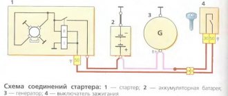
general description
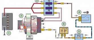
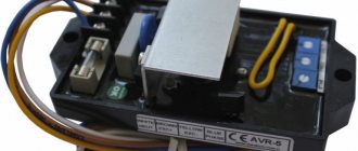
In principle, the Priora generator is not bad. But its power is not enough on luxury models with installed air conditioning. You may hear advice to install an additional diode bridge. But, unfortunately, this option is suitable for those who understand electrical circuits and are comfortable with a soldering iron. The easiest way is to install a three-level voltage regulator.
First you need to check the operation of the generator. Measure the voltage at the positive terminal of the generator and the battery terminals. Without load, the voltage should be at least 13.8 volts, under load - at least 13.5. An ideal option at low temperatures in winter is 14.8-14.3 volts. If there is a difference in the readings, then the contact at the generator output should be cleaned. This can be done with a wire brush or sandpaper. If the parameters are below acceptable values, then you should check the condition of the brushes on the generator and think about replacing the voltage regulator.
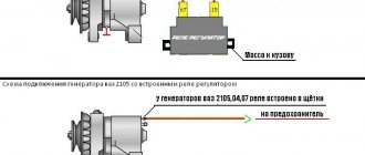
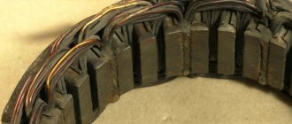
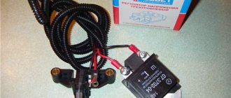
Brush mechanism with relay regulator
On older models of generators, the brushes that transmit current to the rotor winding to create an electromagnetic field that generates electricity could be replaced individually. They were installed in a special device - a brush mechanism, from where they could be easily removed. In modern generators, brushes are mounted complete with an electronic device - a relay regulator. The relay regulator is designed to equalize the voltage supplied to the vehicle's electrical system. A transistor with a threshold for turning off the excitation voltage is built into the relay circuit. He is able to change it depending on the engine speed and, accordingly, the generator. The fact is that without a regulator, as the speed increases, the voltage jumps to 16-18 V, which can lead to failure:
- side lighting lamps;
- low and high beam;
- instrument lighting;
- electric motors of various components.
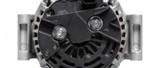
Generator device
The pulley transmits energy from the motor to the shaft using a belt.
Covers on the housing are needed to accommodate the rotor supports, install the unit on the motor and secure the stator. The back cover is needed for the brush assembly and outputs for powering electrical equipment. The stator produces power through a three-phase winding. The rotor is a steel shaft with two bushings. The terminals of this winding are connected to copper rings. The regulator stabilizes the voltage under various factors:
rotor speed delta;
temperature changes in nature.
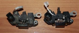
The brush assembly is a plastic element with brushes attached to it that interact with the rotor rings. The electric generator also includes six diodes (three in “-” and three in “+” heat sinks).
Malfunctions of the relay regulator
Most often, the malfunction of the brush mechanism with a built-in regulator is the failure of the semiconductor transistor, a break or a short circuit to the housing. It is also possible for the graphite brushes themselves to wear out or break. This is characterized by a drop or complete disappearance of the charge current. On the Priora this can be seen not only by the battery indicator lamp, but also on the mini display of the instrument panel. It has a charging voltage monitoring function.
The brush mechanism of the generator on the Priora cannot be repaired. In case of any breakdown, you only need to replace the brush assembly.
The process of setting the parameters of the idle air control on a Priora
After replacing the IAC on a car or removing the standard device to check it, it is necessary to perform a procedure called setting parameters or resetting the counter. The procedure is quite simple, for which you should do the following manipulations:
- Turn on the ignition for 5 seconds, then turn it off.
- Turn it on again and then turn it off.
- Start the engine and warm it up for 5 minutes.
- This is quite enough to set the IAC parameters.
After this, we monitor changes in engine operation. The improvements indicate that the IAC was indeed faulty.
In conclusion, it should be noted the importance of the device discussed. On Priora, IAC is often the cause of floating speed. And often the reason is hidden not in the quality of the product, but in a clogged valve, which, due to deposits, cannot efficiently open the channel by the required amount of steps. The reason for its contamination is dust when the filter is not replaced in a timely manner, as well as crankcase gases that adhere to the surface of the IAC. However, oil deposits are not as dangerous as dust entering the collector. Make it a rule to change the air filter in a timely manner in order to increase the service life of not only the IAC, but also the entire engine as a whole.
How to replace brushes on a Priora generator without removing it
All dynamos installed on Russian Priors are convenient in that the brush mechanism can be replaced without removing the unit itself from the car. This is not a very complicated operation, accessible to almost any car owner who knows how to hold tools in his hands. The replacement is carried out in several stages.
- Battery disconnection.
- Removing the power wire with a 10mm wrench from the generator.
- Disconnecting the test lamp input from the connector.
- Removing the rear plastic cover with snaps.
- Using a screwdriver or wrench, unscrew the 2 bolts or nuts securing the brushes.
- Replace the brush mechanism with a new one, connecting the wires.
- Reassemble in reverse order.
After replacing the generator brushes, be sure to measure the flow of charging current to the battery with a voltmeter and compare it with the readings on the Priora instrument panel. We need to make sure that its work is objective.
In the video you can watch a repair involving the replacement of a relay with brushes on a Priora generator:
>
FakeHeader
Comments 41
And don’t throw away the old TRT; it’s easier to rearrange the brushes than to find a replacement if the car already has CAN.
TRT5-01 is a regulator with the ability to control generator voltage via the DFM bus. It contains the Bosch control protocol. On the new Priors, this control bus is activated and the brains that control the engine can control the generator by adjusting the voltage when the voltage drops to idle. Regulators 897.3702 are equally capable of working with generators of the entire line from 800 to 135 amperes, the main parameter is 5 amperes, this is the current that is supplied to the rotor through the excitation brushes, by commutating it the regulator maintains the generator voltage within the required limits. But TRT05, in the absence of a control signal, which was not present on the previous generation Prior, keeps the voltage in the middle position. Due to the absence of this output in 897.3702, it cannot work on new Priors, in which both control (DFM) and power supply (L) are supplied from the ECU. In this case, circuit L is a lamp in the original version, through which, when the ignition is turned on, the power supply to the entire LV circuit is connected in the ECU to the output of the driver, which, when power is supplied to the system, the engine turns on the voltage regulator. And not as in the old scheme, through the charging lamp in the dashboard. Now the charging lamp in the dashboard is turned on by the processor in the dashboard, which receives a signal from the engine ECU via the CAN bus. a bunch of wires were replaced with a computer bus of two wires. Those. on new machines, in the parameters displayed by the scanner during diagnostics, there is also a generator control parameter in %. At the same time, only TRT5 should be installed on new RN generators - the entire old line of domestically produced regulators does not yet have a DFM bus. If you install it instead of TRT5, then there may be problems with the LV power not being turned off when the ignition is turned off, since the L bus from the ECU does not carry pure zero, but some kind of residual voltage and it is possible to drop the battery to zero. You can trick the relay by breaking the circuit using a relay, but you can also get glitches with a charging lamp.
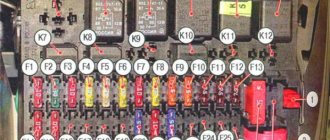
Priora fuse box diagram
| Fuse no. | Current strength, A | "Standard" and "Norm" | “Norma” with air conditioning and “luxury” |
| F1 | 25 | Engine cooling radiator fan | Reserve |
| F2 | 25 | Heated rear window | Mounting block, rear window heating relay (contacts). Electrical package controller, contact “10” of XP2 block. Rear window heating element. |
| F3 | 10 | Right headlight, high beam | Right headlight, high beam lamp. Instrument cluster, headlight high beam indicator. |
| F4 | 10 | Left headlight, high beam | |
| F5 | 10 | Sound signal | Mounting block, horn relay. Sound signal. |
| F6 | 7.5 | Left headlight, low beam | |
| F7 | 7.5 | Right headlight, low beam | |
| F8 | 10 | Alarm signal | Mounting block, alarm relay. Alarm sound. |
| F9 | 25 | Priora heater fuse | Reserve |
| F10 | 7.5/10* | Interior lighting, instrument panels, brake light | Instrument cluster, pin “20”. Brake light switch. Brake light bulbs. Interior lighting unit. Interior lighting. The door sill light on the right front door. Additional brake signal. |
| F11 | 10/20* | Wiper | Mounting block, high speed windshield wiper relay. Switch for cleaners and washers, contact “53a”. Wiper and washer switch, contact “53ah”. Heated rear window switch. Mounting block, rear window heating relay (winding). Windshield wiper motor. Rear window wiper motor (2171,2172). Windshield washer motor. Rear window washer motor (2171,2172). Airbag control unit, pin “25”. |
| F12 | 20/10* | Terminal 15 devices | Instrument cluster, pin “21”. Electrical package controller, contact “9” of block X2. Electromechanical power steering control unit, contact “1” of block X2. Reversing light switch. Reversing lamps. Parking system control unit, contacts “11” and “14”. |
| F13 | 15 | Cigarette lighter fuse Priora | |
| F14 | 5 | Left headlight, parking light, license plate light, trunk light | Side light lamps (left side) Instrument cluster, main light indicator License plate lights Trunk light Electrical package controller, pin “12” of block X2 |
| F15 | 5 | Right headlight, parking light | Side light lamps (right side) Glove compartment lamp |
| F16 | 10 | Terminal 15 ABS | Hydraulic unit, contact "18" |
| F17 | 10 | Left fog lamp | |
| F18 | 10 | Right fog lamp | |
| F19 | 15 | Seat heating | Seat heating switch, contact "1" Front seat heaters |
| F20 | 5/10* | Immobilizer control unit | Recirculation switch (switch on) Mounting block, relay for low beam headlights and parking lights (automatic lighting control system) Heater electric fan relay Automatic lighting control switch Windshield wiper and external lighting control unit, contacts “3”, “11” Automatic climate control system controller installation, pin “1” Automatic window cleaning system sensor (rain sensor), pin “1” |
| F21 | 7.5/5* | Rear fog lights | Light switch, contact "30" Diagnostic block, contact "16" Clock Automatic climate control system controller, contact "14" |
| F22 | -/20* | Reserve | Windshield wiper motor (automatic) Mounting block, windshield wiper relay and windshield wiper high speed relay, (contacts) |
| F23 | -/7.5* | Reserve | Windshield wipers and external lighting control unit, pin “20” |
| F24-F30 | Reserve | ||
| F31 | 30 | Electrical package control unit | Electrical package controller, terminal “2” of block X1 Electrical package controller, terminal “3” of block X1 Driver’s door module, pin “6” Threshold light of the left front door |
| F32 | Reserve | ||
* - for the “Norma” configuration with air conditioning and “luxury”
| Relay | "Norm" | "Norma" with air conditioning | "Lux" |
| K1 | relay for turning on the electric radiator fan of the engine cooling system | Reserve | Relay for turning on the low beam and side lights of the headlights (automatic lighting control system) |
| K2 | rear window heating relay | ||
| K3 | starter activation relay Priora | ||
| K4 | additional relay (ignition relay) | ||
| K5 | space for backup relay | ||
| K6 | windshield washer and wiper relay | ||
| K7 | headlight high beam relay | ||
| K8 | horn relay | ||
| K9 | alarm relay | ||
| K10 | Reserve | Fog light relay | |
| K11 | Reserve | Front seat heating relay | |
| K12 | Reserve | ||
Blocks under the hood
Fuse box
This unit is located next to the battery.
Photo - diagram
Description Option 1
| F1 | 60A Generator power circuit (generator to battery connection) |
| F2 | 50A Electric power steering power supply circuit |
| F3 | 60AC generator power circuit (connection of the generator to the battery) |
| F4 | 30A ABS control unit |
| F5 | 40A ABS control unit |
| F6 | 30A Engine control circuits |
Description Option 2
| F1 | 15A Air conditioning compressor electromagnetic clutch circuit |
| F2 | 40A Heater fan motor |
| F3 | Reserve |
| F4 | 50A Heated windshield element |
| F5 | 30A Main cooling fan motor |
| F6 | 30A Electric motor for additional cooling fan |
Relay and fuse box
It is located next to the fuse box and is covered with a protective cover.
Option 1
Appointments
- Right electric fan power supply fuse (30 A)
- Left electric fan power supply fuse (30 A)
- Right electric fan relay
- Additional relay (sequential activation of left and right electric fans)
- Left electric fan relay
- Heater fan power supply fuse (40 A)
- Compressor power supply fuse (15 A)
- Heater fan relay
- Compressor relay
Option 2
Designation
- Heater fan maximum speed
- Right fan
- Fan sequential relay (low speed)
- Left fan
- Left fan fuse (low speed)
- Right fan
- Heater fan
- Compressor
- Heater fan
- Compressor relay
Generator relay Lada Priora 2170 (Lada PRIORA)
Found an error in the compatibility of a spare part with a car? Report it to our specialists.
AutoPro experts know additional configurations:
- Generator regulator relay, (charging relay) standard equipment: VRR0110, 21103701500, AVR37803O7
- Generator voltage regulator relay type: Bosch; Generator current, A: 80-120: 230994, F00M145352, 130603, 082988352, IB230, 333569, 82988352, IB230
- Generator regulator relay type: Iskra/Letrika; Generator current, A: 45-80: 134861, 139513, IK543, VRIK149, 130511, ARE9008
- Relay regulator (voltage) type: Bosch; Generator current, A: 80-140: 9459741, 232927, 8637851, IB229, VRB221, BOR229, F00M145369, F00MA45211, 130604, 237267, F00MA45207, VRB369, CQ1010468, C Q1010468, IB229, KO7501543, ARE0041