A three-level voltage regulator (VR) is one of the main components of the generator device. As you know, the failure of a generator can lead to the inoperability of the car as a whole, so the condition of all its parts and mechanisms must always be in working order. You can learn more about the regulator, its types, as well as diagnostics from this material.
Which TRN is suitable for LADA
| Generator, article number | Automobile | TRG, article number |
| 26.3701, 37.3701, 371.3701, 372.3701 | VAZ-2107, -2108, -2109, -2110, OKA | 67.3702-01 |
| 3002.3771, 332.3771, 3202.3771, 3212.3771, 4302.3771, 94.3701, 9402.3701, 9422.3701, 3740.3771-38, 3743.3771-61, 3747.3771- 93, eld-a-21214, LG01214 | VAZ, GAZ | 67.3702-02 |
| 4052.3701, 409.3701, PRAMO “ISKRA” 5102.3771, -10, 5112.3771, -10, 5122.3771, -10, -30, 5142.3771, AAK 5727 | VAZ, GAZ, UAZ with generators PRAMO “ISKRA” 5102.3771, 5122.3771 | 67.3702-04 |
| G222 | VAZ-2104, -2105, -2107 | 67.3702-09 |
| 26.3701, 37.3701, 371.3701, 372.3701 | VAZ-2107, -2108, -2109, -2110, OKA | 67.3702-11 |
| 3002.3771, 332.3771, 3202.3771, 3212.3771, 4302.3771, 94.3701, 9402.3701, 9422.3701, 3740.3771-38, 3743.3771-61, 3747.3771- 93, eld-a-21214, LG01214 | VAZ, GAZ | 67.3702-12 |
| generators with an additional three diodes, the excitation winding of which is connected to the positive circuit | 673.3702 |
Installation and connection instructions
For Lada cars (except Vesta, XRAY)
, photo author:
2.
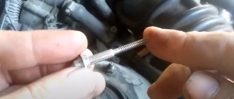
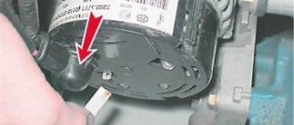
Remove the plastic casing of the generator. To do this, first disconnect the generator excitation wire. Then unscrew the nut from the stud (10mm wrench) and move the power wire to the side. Next, 3 latches on the plastic casing are unfastened.
3.
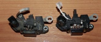
Remove the standard voltage regulator from the generator. To do this, unscrew two screws ("8" key) and disconnect the wire.
4.
Install a three-level voltage regulator on the generator instead of the standard one.
5.
Output 2 wires for the control module. The module itself should be mounted in conditions of reliable contact with the “ground” and as far as possible from the possibility of moisture ingress. For example, on a hairpin near the right headlight.
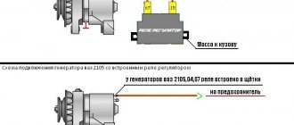
For Lada Vesta, XRAY cars (with Valeo TG12C209 generator).
This generator is no different from the previous ones, the only difference is in the voltage regulator. It communicates with the engine ECU via a “lin” interface. The task of this “lin” is to avoid loss of throttle response at power modes. By installing the TRN, we cut off the ability to control the regulator using the ECU!
For this generator there is no ready-made solution in the form of a TRN yet, so the design will have to be modified.
- three-level voltage regulator (article 67.3702-01)
- 2-pin block 904576 NORD YADA
- generator voltage regulator (leave the standard one (if the brushes are live) or ARV1103AD)
- wire for powering the regulator (2 meters)
2.
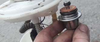
Remove the voltage regulator, open the cover and clean everything under it. Reinstall the cover.
3.
Isolate the negative brush from ground (for example, drill out the negative outlet, place washers). It is necessary to completely eliminate contact between the regulator and the generator.
4.
Solder the female connector to the brushes.
5.
Solder the male connector to the 3-level regulator. Also, connect an additional wire to the positive output, which is needed to power the regulator and rotor.
- Output “Ш” on the regulator goes to the negative brush.
- Output “+” - to the positive brush.
The “+” output needs to be supplied with 12V, which appears when the ignition is turned on:
PRICE CATEGORIES
To find out the cost of a voltage regulator for a VAZ 2114, it is advisable to simply go to the nearest car market and ask, the price range may vary. This factor is influenced by the type of components and the region in which the store is located.
Typically, the price of a two-level standard regulator, which is installed at the factory in the VAZ 2114 and their families, can range from 300 to 1200 rubles, here the reason for the fluctuation depends on the quality and the specific manufacturer; more reliable and high-quality options will always be somewhat more expensive than their low-quality counterparts. As for three-level models, their price starts from 1,500 rubles, but their productivity is much greater. During the purchase, it is advisable to immediately ask the seller to check the functionality so that there are no problems in the future.
Checking the work
- Switch position “min” - for operation at high ambient temperatures (above 20ºС), as well as during operation in particularly difficult conditions (traffic in traffic jams, long climbs in the mountains, etc.);
- The middle position of the switch is for operation at ambient temperatures from 0ºС to 20ºС;
- The “max” switch position is for operation at low ambient temperatures (below 0ºC), as well as for recharging a discharged battery.
Average load (PTF, dimensions, music and heater fan at first speed)
:
Maximum load, maximum number of consumers activated
:
Will you be installing a three-level voltage regulator on your car? Take part in the survey and leave your feedback in the comments.
Let us remind you that another reason for low voltage on the on-board network may be a bad ground.
Share on social networks:
Why do you need a three-level voltage regulator?
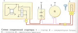
A modern car is densely saturated with numerous instruments and devices, the performance of which is determined by receiving power from the on-board DC network. When the engine is running, the current source is an electric generator, the rotor of which rotates due to the presence of a mechanical connection with the shaft. The engine speed varies widely, causing the generator output voltage to fluctuate. To reduce voltage variations to the required value, a stabilizer is installed at the output of the rectifier, which is made in the form of a relay regulator.
SHI stabilizer
Pulse-width stabilizers are characterized by more stable operation, that is, an almost constant voltage is supplied to the vehicle network, and small deviations within the normal range are smooth. The device circuit uses the same parts as in the original, but at the same time the K561TL1 microcircuit is included. This made it possible to assemble a multivibrator and a short pulse shaper on the 1st node. The output switch control unit has also been simplified due to the use of a field-effect transistor with increased power.
Car alternator output voltage problem
The list of functions of the generator necessarily includes recharging the on-board battery, which is carried out with a certain current to ensure a long service life. The simplest way to set its value is to slightly exceed the voltage taken from the output of the relay-regulator over the current value of the battery voltage. In this case, a serious problem immediately arises, which is due to the fact that, depending on the ambient temperature, the value of this excess should be different.
An obvious and fairly easily implemented solution to obtain a given output voltage using temperature correction of the regulator response threshold by installing an appropriate sensor is of low efficiency. The reason for this is that the temperature in the engine compartment, due to its proximity to a heated engine, differs from the air temperature, and it is not possible to determine the degree of this difference by simple means.
Another problem in determining the set value of the charging current is due to the fact that even at a constant ambient temperature, the load on the on-board network varies within wide limits. This leads to a “failure” in the battery charge level and difficulty starting a cooled engine after parking.
A good way to solve these problems is to switch to a relay-regulator, which makes the necessary adjustments by discretely changing the voltage that the generator creates. The specified value of the response threshold of this device is set by the driver independently using a three-position toggle switch. Some regulators connect automatically and contain an internal sensor that monitors the instantaneous value of the on-board network voltage. In both cases, the selection of the cutoff threshold is carried out taking into account external factors, primarily the current temperature and operating conditions of the vehicle.
Standard regulator diagram
The usual voltage regulator circuit provides diodes of different levels. However, their barriers may differ significantly. This is primarily due to a sharp change in voltage in the system. The current should also be taken into account. Among other things, the regulators have radiators.
Their main task is to cool the diodes. The position of the device is directly controlled using a toggle switch. The voltage regulator circuit also contains an electric drive strip, which closes the circuit.
Operating modes of a three-level relay-regulator
The “Minimum” level or mode, which corresponds to the generator output voltage of 13.6 V, is used for operation at air temperatures above 20°C and is used under high engine load (traffic jams, mountainous areas).
The “Normal” level assumes an output voltage of 14.2 V, corresponds to the average load on the engine, and is used in spring and autumn at ambient temperatures of 0–20 °C.
It is recommended to switch the regulator to “Maximum” mode at negative air temperatures. In the warm season, it is activated for a short time to charge the battery, which is heavily “dead” after a long stay, for example, by the speaker system or for other reasons.
The consumer qualities of some models of three-level relays are improved by introducing an additional semiconductor switch into the circuit, which ensures safe engine starting. This unit blocks the supply of current to the generator windings if it does not have a stable output voltage.
Something else useful for you:
FakeHeader
Comments 33
Several years ago I developed a PP circuit with a temperature sensor, the same as a three-level one, only the voltage changes automatically depending on the temperature.
When I created my relay regulator, the goal was to create a reliable relay regulator that would make it easier to start the engine in winter, because... In cold weather, I had to remove the battery and heat and charge it at home, which was not convenient. When I did it, the problem with starting the engine in cold weather disappeared. Moreover, other useful qualities appeared. Like increasing battery life. The engine began to start with batteries that had not started it before (smaller capacity or old, dead ones). more stable voltage.
here's a video of how it works,
Anyone interested can order from me. vk.com/id6807678
The bridge's kick came from him(((
Handsome, my friend)) I installed it for myself and also noticed such a hat. Everything flickers, today I’ll redo it +100500 for you :)
The regulator just broke. Thank you I will install it)
By the way, it is more convenient to route the wire through a large hole that looks like a circle with a rectangle. It seems to be under W. We don't have an output for this W. As far as I understand Gennady’s circuit, this is one of the generator windings (phase). This hole is on the right side of the cover (if we assume that B+ and D are on the left) and is located vertically between the holes for B+ and D.
Advantages of using a three-level relay and features of its installation
In practice, three-level regulators designed for the 9th and older VAZ models have become widespread. This is due to the fact that replacing the standard relay with a three-level one provides the following advantages:
- stabilization of alarm operation in severe frosts;
- increasing the brightness of headlights and interior lighting lamps;
- a sharp increase in the efficiency of the heater;
- increasing the speed of power windows.
Kits for VAZ “ten” and 14th models are quite common; there are also devices for “Volga” and “Gazelle”. Their use on these vehicles gives a similar effect.
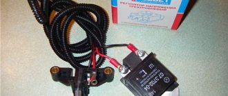
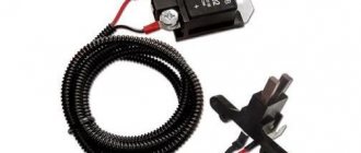
A three-level relay-regulator is purchased in the form of a ready-to-install kit, which includes detailed illustrated instructions. The main elements of the kit are a contact group, a relay itself with a slide-type switch for selecting the stabilization voltage, and connecting wires.
Before starting replacement work, it is advisable to charge the battery and then disconnect its negative terminal.
The contact group of the new device is mounted directly on the seats of the previously dismantled old one; installation does not require the use of adapters and other auxiliary elements. The connecting wire is pulled through the generator cover (you may need to cut a hole in it to the required size), and the relay itself is attached to a free mounting stud with the terminals facing down. When installing, additionally check for reliable ground contact. After installing and assembling the generator, we check it.
Independent connection of the relay regulator to the generator’s on-board network (step-by-step instructions)
When installing a new control device, the following points must be taken into account:
- Before performing the task, it is necessary to diagnose the integrity and reliability of the contacts. This is a cable that runs from the vehicle body to the generator set housing.
- Then connect terminal B of the regulatory element to the positive contact of the generating set.
- It is not recommended to use twisted wires when making connections. They overheat and become unusable after a year of use. Soldering should be used.
- It is recommended to replace the standard conductor with a wire whose cross-section is at least 6 mm2. Especially if, instead of the factory generator, a new one is installed, which is designed to operate under current conditions above 60 A.
- The presence of an ammeter in the generator-battery circuit allows you to determine the power of power sources at a specific time.
Remote controller connection diagram
Connection diagram for remote type devices
This device is installed after the wire into which it will be connected is determined:
- In older versions of Gazelles and RAF, mechanisms 13.3702 are used. They are made in a metal or polymer case and are equipped with two contact elements and brushes. It is recommended to connect them to the negative open circuit; the outputs are usually marked. The positive contact is taken from the ignition coil. And the output of the relay is connected to the free contact on the brushes.
- VAZ cars use devices 121.3702 in a black or white case; there are also double modifications. In the latter, if one of the parts breaks down, the second regulator will remain working, but you need to switch to it. The device is installed in the open circuit of the positive circuit with terminal 15 to the contact of the B-VK coil. The conductor number 67 is connected to the brushes.
In newer versions of the VAZ, the relays are installed in the brush mechanism and connected to the ignition switch. If the car owner replaces the standard unit with an AC unit, then the connection must be made taking into account the nuances.
More details about them:
- The need to fix the unit to the vehicle body is determined by the car owner independently.
- Instead of a positive output, contact B or B+ is used here. It must be connected to the car's electrical network via an ammeter.
- Remote type devices are usually not used in such cars, and built-in regulators are already integrated into the brush mechanism. There is one cable coming from it, designated D or D+. It must connect to the ignition switch.
In cars with diesel engines, the generator unit can be equipped with output W - it is connected to the tachometer. This contact can be ignored if the unit is installed on a gasoline modification of the car.
User Nikolay Purtov spoke in detail about installing and connecting remote devices to a car.
Checking the connection
The engine must start. And the voltage level in the car’s electrical network will be controlled depending on the number of revolutions.
Perhaps, after installing and connecting a new generator device, the car owner will encounter difficulties:
- when the power unit is activated, the generator unit starts, the voltage value is measured at any speed;
- and after the ignition is turned off, the vehicle engine runs and does not turn off.
The problem can be solved by disconnecting the excitation cable, only then will the engine stop.
The engine may stall when the clutch is released and the brake pedal is pressed. The cause of the malfunction is residual magnetization, as well as constant self-excitation of the unit winding.
To avoid this problem in the future, you can add a light source to the gap in the exciting cable:
- the light will light when the generator is turned off;
- when the unit starts, the indicator goes out;
- the amount of current that passes through the light source will not be sufficient to excite the winding.
The Altevaa TV channel talked about checking the connection of the regulatory device after connecting the motorcycle to a 6-volt network.
Study, connection and diagnostics of a three-level voltage regulator
A three-level voltage regulator (VR) is one of the main components of the generator device. As you know, the failure of a generator can lead to the inoperability of the car as a whole, so the condition of all its parts and mechanisms must always be in working order. You can learn more about the regulator, its types, as well as diagnostics from this material.
Advantages of regulators
As mentioned earlier, regulators can save battery life. This gives the driver tremendous opportunities. First of all, any problems with warming up disappear. Even on frosty days, the engine will start much easier. At the same time, problems with the alarm system, if any, may disappear. For many motorists, again in winter, it does not function well.
Among other things, the power of the lamps will increase. In this case, visibility in low and high beam will improve significantly. Also, a three-level voltage regulator can affect the operation of the stove. According to motorists, it has the ability to work much better with a fully charged battery. You can also notice an increase in the speed of switching the power windows. As a result, the driver is deprived of many problems.
Characteristics of the voltage regulator
What is a DC regulator, what role does it play in a car alternator, what voltage should the alternator produce? Is it possible to raise and increase the number of output parameters using a simple three-level device? First, let's look at what the design of the element is and what its purpose is.
Purpose
So, what is an electronic car generator voltage regulator used for? When starting a power unit, as is known, the crankshaft begins to rotate first; this occurs as a result of the influence of direct current on it. The current in amperes initiates the movement of the rotor mechanism, after which the generator unit begins to function. A constant voltage regulator is used to control all processes.
If the voltage is not high, and due to the failure of the generator voltage regulator there is no power to the mechanism, the unit will not be able to start. If there is no generator power, the current in amperes will simply not be supplied to the equipment. A simple voltage regulator makes it possible to keep the current in amperes in the specified range; this is its main purpose.
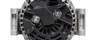
Design
Now let’s look at the issue of the device: any increasing pH, even simple and homemade, will consist of:
- Rectifier block. This element includes several diode components, usually their number is six. All components of this block are connected to each other via a special bridge.
- Rotary mechanism with winding. This device rotates around an axis; its purpose is to generate a magnetic field inside the unit.
- Stator mechanism. On the body of this device there are three windings connected to each other. Thanks to these windings, it is possible not only to provide a higher charge, but also to increase power for the car battery. They also make it possible to supply current to the entire electrical network of the vehicle.
- Impellers. This element is installed on the outer part of the mechanism. The impeller is used to blow and cool the winding; without it, the latter may overheat.
- Case cover. Its purpose is to hide all the constituent structural parts of the unit, thereby ensuring reliable protection of the device from dirt and dust. Depending on the model, the lid may have a special casing - if the design implies its presence, then the regulatory element will be located immediately behind it.
- And the relay itself. If the generator produces a high voltage that is not typical for the on-board network, or is too low, then the relay will stabilize this parameter to the desired level. The stabilizer must provide exactly the optimal voltage, not increased or decreased (video author - Vitaly Galankin).
Principle of operation
If you decide to connect a winding without a regulator to a power source, then the DC value after connection will, of course, be increased. Using this device, the value is equalized, which helps prevent equipment breakdown. The control device of an asynchronous generator unit is, in fact, a switch. If the voltage at the generator terminals is not normal, the mechanism adjusts the parameter to the desired value.
REPLACING THE REGULATOR WITH A NEW OWNER ON YOUR OWN
Now we need to figure out how to replace the VAZ 2114 voltage regulator. First, you need to understand that it itself is located inside the generator housing. Mechanically, it consists of a special armature, an electromagnet and a relay. To disassemble the generator and remove the regulator we will need the following necessary tools:
- Set of open-end wrenches;
- Various screwdrivers.
Typically, repairs involve a complete replacement, but the generator itself does not need to be completely removed from the car. However, first you need to remember to remove the terminals from the battery, 12 V is not much, but it will be unpleasant to get hit. After the car has been de-energized, you need to remove the caps from the generator terminals and unscrew them with a screwdriver. Now you need to carefully remove the protective casing from the generator; on the VAZ 2114 it is equipped with spring latches; it is important not to break them right away. Now the voltage regulator of the VAZ 2114 generator will be visible under the casing; you need to unscrew its fastenings and pull it out of the seats along with the brushes.
Carrying out diagnostics of RN with your own hands
Now we’ll tell you how to check a three-level voltage regulator with your own hands. The procedure for checking the regulator can be carried out both at a service station and in a garage, but we will consider the second option. Testing a voltage regulator of 40 amps or less should be done using a tester - a voltmeter or a multimeter. It should also be taken into account that fault detection in the operation of the launch vehicle should be carried out exclusively with a fully charged battery.
So, how to check the generator voltage regulator using a tester:
- First of all, you need to open the hood and turn the key in the lock, turning on the ignition.
- Next, the power unit is started. The engine should idle for some time; to obtain more accurate diagnostic data, it is recommended to turn on the optics. The engine speed when running should be around 2.5-3 thousand. For the internal combustion engine to switch to this operating mode, you usually need to wait about 10 minutes.
- Then the tester probes are connected to the battery terminals. When you connect the tester, diagnostic indicators should appear on its display, ideally they should be approximately 14.1-14.3 volts.
If the check shows other values, be they higher or lower, then you need to start repairing the generator unit. But as practice shows, the problem usually lies precisely in the launch vehicle, so most likely it will have to be replaced. Before you begin diagnostics, make sure that the belt is properly tensioned . During diagnostics, contacts must not be closed, as this may cause deformation and failure of the rectifier unit.
Stories from our readers
“Fucking basin. "
Hi all! My name is Mikhail, now I’ll tell you a story about how I managed to exchange my two-wheeler for a 2010 Camry. It all started with the fact that I began to be wildly irritated by the breakdowns of the two-wheeler, it seemed like nothing serious was broken, but damn it, there were so many little things that really started to irritate me. This is where the idea arose that it was time to change the car to a foreign car. The choice fell on the melting Camry of the tenth years.
Yes, I had matured morally, but financially I just couldn’t handle it. I’ll say right away that I am against loans and taking a car, especially not a new one, on credit is unreasonable. My salary is 24k a month, so collecting 600-700 thousand is almost impossible for me. I started looking for different ways to make money on the Internet. You can’t imagine how many scams there are, what I haven’t tried: sports betting, network marketing, and even the volcano casino, where I successfully lost about 10 thousand ((The only direction in which it seemed to me that I could make money was currency trading on the stock exchange, they call it Forex. But when I started delving into it, I realized that it was very difficult for me. I continued to dig further and came across binary options. The essence is the same as in Forex, but it’s much easier to understand. I started reading forums, studying trading strategies. I tried it on a demo account, then opened a real account. To be honest, I didn’t manage to start earning money right away, until I understood all the mechanics of options, I lost about 3,000 rubles, but as it turned out, it was a precious experience. Now I earn 5-7 thousand rubles a day. I managed to get the car buy after half a year, but in my opinion this is a good result, and it’s not about the car, my life has changed, I naturally quit my job, I have more free time for myself and my family. You’ll laugh, but I work directly on the phone)) If If you want to change your life like me, then here’s what I advise you to do right now: 1. Register on the site 2. Practice on a Demo account (it’s free). 3. As soon as you get something on the Demo account, top up your REAL ACCOUNT and go to REAL MONEY! I also advise you to download the application to your phone, it’s much more convenient to work from your phone. Download here.
2. MAX - both diodes are used 3. MID - only diode D2 is used. In such a scheme, any switching is painless - in intermediate states of the toggle switch there will be mode No. 2.
I connected the red wire to the “In” terminal, and the black wire to the “Out” terminal.
- When toggle switch S1 is in position “1” , the generator operates in normal mode.
- In position “3” of toggle switch S1, one Schottky diode is connected. The voltage at the generator output increases by 0.3-0.4V.
- When toggle switch S1 is in position “2” , two Schottky diodes connected in series are connected to the generator circuit. The generator output voltage increases by (0.3-0.4V)*2.
The arrangement of parts in the case and the fastening of the metal strip on the case cover are shown.
To connect the box with diodes to the generator, I had to remove the plastic cover. I ran the wires through the slot in the generator cover.
- I soldered the male terminal to the red wire. It connects to the wire with the “mother” coming from the additional diodes of the diode bridge.
- I soldered the “mother” terminal to the black wire with the wire sealed at 90 degrees. This wire connects directly to the excitation terminal of the voltage regulator.
Having connected these wires to the generator circuit, we put the plastic cover in place and connect the standard wires going to the gene. This is what it looks like assembled:
Next, we screw the plastic box with diodes to the car body between the adsorber and the right headlight. To make it look better, we put plastic on the wire and lay it along the standard wiring and secure it with clamps.