| Click to open full size |
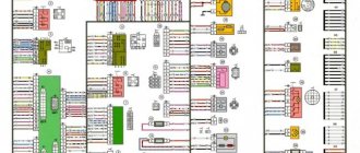
1 – front lights; 2 – side direction indicators; 3 – headlight washer electric motor*; 4 – voltage regulator; 5 – battery charge warning lamp relay; 6 – Battery; 7 – starter; 8 – generator; 9 – headlights; 10 – gearmotors for headlight cleaners*; 11 – sound signals; 12 – spark plugs; 13 – carburetor solenoid valve; 14 – ignition coil; 15 – windshield wiper gearmotor; 16 – coolant temperature indicator sensor; 17 – ignition distributor; 18 – windshield washer electric motor; 19 – oil pressure indicator sensor; 20 – oil pressure warning lamp sensor; 21 – brake fluid level warning lamp sensor; 22 – plug socket for a portable lamp; 23 – relay for turning on headlight cleaners and washer*; 24 – relay for turning on low beam headlights; 25 – relay for turning on the high beam headlights; 26 – windshield wiper relay; 27 – additional fuse block; 28 – main fuse block; 29 – additional resistor of the heater electric motor; 30 – reverse light switch; 31 – brake light switch; 32 – heater electric motor; 33 – relay-breaker for alarm and direction indicators;
34 – parking brake warning lamp switch; 35 – alarm switch**; 36 – cigarette lighter; 37 – switch for cleaners and headlight washers*; 38 – heater motor switch; 39 – external lighting switch; 40 – three-lever switch; 41 – ignition switch; 42 – instrument lighting switch; 43 – lamp switches located in the door pillars; 44 – interior lamps; 45 – oil pressure gauge with insufficient pressure warning lamp; 46 – fuel level indicator with reserve warning lamp; 47 – tachometer; 48 – parking brake warning lamp; 49 – battery charge indicator lamp; 50 – control lamp for the carburetor air damper; 51 – side light indicator lamp; 52 – turn signal indicator lamp; 53 – control lamp for high beam headlights; 54 – speedometer; 55 – switch for the carburetor air damper warning lamp; 56 – relay-interrupter for the parking brake warning lamp; 57 – coolant temperature indicator; 58 – brake fluid level warning lamp; 59 – differential lock warning lamp; 60 – switch for differential lock warning lamp; 61 – rear lights; 62 – license plate lights; 63 – sensor for level indicator and fuel reserve.
The order of conditional numbering of plugs in blocks:
a – windshield and headlight wipers, windshield wiper relay breaker; b – relay-breaker for alarm and direction indicators; c – three-lever switch; d – hazard warning switch.
* Installed on parts of manufactured cars; ** on cars produced in the 90s, due to the installation of breaker relays 33 without the fifth terminal, the brown wire connecting switch 35 to breaker relay 33 is missing.
Schematic electrical diagrams, connecting devices and pinouts of connectors
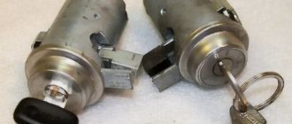
The ignition switch in cars of the VAZ family fails from time to time due to weakening of the contact posts or burning of the contacts inside it. It also happens that the cams of a plastic roller are produced. You can disassemble the lock and clean it, but it’s better to just replace it with a new one, considering that it costs pennies compared to imported locks.
But if connecting the wires together did not result in the starter operating (or it did not turn on the first time), check the solenoid relay on the starter. The contact spots on it may also burn out, which will prevent the circuit from closing normally. Alternatively, you can use a screwdriver to short-circuit the two large terminals on the solenoid relay (before doing this, put the car in neutral and use the handbrake). When closed, the starter should begin to spin vigorously. If this happens, remove and change the solenoid relay. If the starter rotates “sluggishly” when it closes, you will have to remove it and check the condition of the brushes.
All operations are performed with your own hands, without the help of car service specialists. Moreover, the price of an ignition switch on a VAZ2106 is up to 100 rubles. To replace it, you will need to know the pinout of the wires coming from it, for which the editors of the site 2 Schemes.ru have prepared a large reference material.
The ignition switch is designed not only to start the engine - it performs several functions at once:
- supplies voltage to the vehicle’s on-board network, closing the circuits of the ignition system, lighting, sound alarm, additional devices and instruments;
- at the driver’s command, turns on the starter to start the power plant and turns it off;
- turns off the power to the on-board circuit, preserving the battery charge;
- protects the car from theft by fixing the steering shaft.
Breakdowns
Most often, the contact group fails, since it is made of plastic into which copper contacts are inserted; due to the flow of high currents and weak contact between the brackets, heating occurs. Due to high temperature, the plastic is deformed and damages the contact group.
The mechanical part fails much less often, but it also happens. It becomes damaged due to prolonged use, the springs in the lock sag, the lock becomes loose, which leads to its jamming or the ability to turn it with almost any key, which reduces the car’s protection to zero.
About the castle
The ignition switch on the Niva is a part that has a mechanical and electrical part. Each part is responsible for specific functions. The mechanical part protects the car from turning on the ignition with another key and increases the car’s protection against theft. The electrical part (contact group) is responsible for closing the power supply and vehicle control circuits.
Each of the parts can fail, which will lead to the inability to start the engine or stop it altogether.
Chevrolet Niva hub - replacement
To replace the wheel bearing in the field, you need to pull out the hub. This is carried out according to the following plan.
1. Dismounting the conical bushing.
2. Unlocking the nuts. The problem may lie in the fact that they often lick off or turn sour. In this case, you can use a chisel and a light hammer.
3. Use the nineteenth socket or wrench to remove the lever clamps. They are located both front and back.
4. The locking plates are removed. These are metal perforated strips that are often overlooked.
5. The seventeenth and tenth keys require removing the circuit pipes.
6. A stop is installed under the lever. Using two twelfths keys, unscrew the nut fixed on the upper arm retainer bolt.
7. The lower block is also unscrewed in the same way.
8. When there are no fasteners left, it is possible to pull out the entire system at once.
9. By fixing the steering knuckle with a clamp, you can knock out the hub.
10. After this, the screws securing the knuckle to the lever mechanism are removed.
Knowing the structure of the front wheel hub of Niva 21213, you can carry out repairs yourself, without contacting a service center.
Chevrolet Niva ♥♥♥ › Logbook › Electrical diagram of the Chevrolet NIVA car
Removing and installing the ignition switch. replacing the ignition lock cylinder Electrical diagram of a Chevrolet NIVA car Designations for the electrical diagram of a Chevrolet Niva car - engine 2123:
1 — right headlight; 2 — sound signal; 3 — engine compartment lamp; 4 — engine compartment lamp switch; 5 - starter; 6 - battery; 7 - generator; 8 — air temperature sensor; 9 — left headlight; 10 — power window switch for the right front door; 11 — gear motors for electric windows; 12 — switch for interior lighting in the door lock; 13 — gear motor for door lock; 14 — connection block to the right front speaker of the audio system; 15 — heater electric motor; 16 — speed sensor; 17 — windshield washer electric motor; 18 — windshield wiper electric motor; 19 - switch for interior lighting in the driver's door lock; 20 — gear motor for locking the driver’s door lock; 21 — brake fluid level sensor; 22 — connection block to the left front speaker of the audio system; 23 — power window switch of the right front door; 24 — left front door power window switch; 25 — mounting block; 26 — relay for turning on electric windows; 27 — relay for turning on the sound signal; 28 — diagnostic block; 29 — control unit for the door lock system; 30 — connection block to the wiring harness of the front seat heating system; 31 — connection block to the injection system wiring harness; 32 — instrument cluster; 33 — right side turn signal; 34 — glove box lighting lamp; 35 — switch for the glove compartment lighting lamp; 36 — ignition switch; 37 — brake signal switch; 38 — reverse light switch; 39 — control lamp block; 40 — electric headlight range control regulator; 41 — instrument lighting regulator; 42 — steering column switch; 43 — left side direction indicator; 44 — heater motor switch; 45 — additional resistor of the heater electric motor; 46 — parking brake sensor; 47 — rear fog light switch; 48 — fog lamp switch; 49 — rear window heating switch; 50 — external lighting switch; 51 — alarm switch; 52 — connection block to the right rear speaker of the audio system; 53 — electric fuel pump with fuel level sensor; 54 — backlight lamps for heater control levers; 55 — differential lock activation sensor; 56 — cigarette lighter; 57 — backlight lamp; 58 — control unit for the automobile anti-theft system; 59 — interior lamp; 60 — canopy for individual interior lighting; 61 — connectors for connecting to the head unit of the audio system; 62 — connection block to the left rear speaker of the audio system; 63 — right rear light; 64 — trunk lighting; 65 — license plate lights; 66 — tailgate glass washer motor; 67 — tailgate glass wiper motor; 68 — rear door glass heating element; 69 — additional brake signal; 70 - left rear light
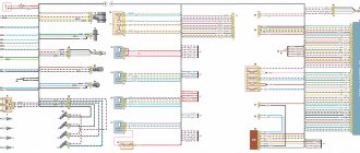
Electrical connection diagram of the engine control system
Designations for the electrical connection diagram of the engine control system:
1 - spark plugs; 2 — nozzles; 3 — ignition module; 4 - controller; 5 - main relay; 6 - fuse box that protects the power circuits of the main relay and the left electric fan relay; 7 — right electric fan relay; 8 - fuse protecting the constant power supply circuit of the controller; 9 — mass air flow sensor; 10 — throttle position sensor; 11 — coolant temperature sensor; 12 — idle speed regulator; 13 — oxygen concentration sensor; 14 — knock sensor; 15 — crankshaft position sensor; 16 — solenoid valve for purge of the adsorber; 17 — electric motor of the left fan of the cooling system; 18 - additional resistor; 19 — electric motor of the right fan of the cooling system; 20 — sensor of the warning lamp for insufficient oil pressure; 21 — electric fuel pump relay; 22 — coolant temperature indicator sensor; 23 — left electric fan relay; 24 — additional relay for the right electric fan; 25 - fuse box that protects the power circuits of the additional relay, the right electric fan relay and the electric fuel pump relay; A - to the “-” terminal of the battery; B - to the “+” terminal of the battery; C - block connected to the instrument panel wiring harness; G1, G2 - ground connection points
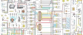
Electrical diagram of VAZ 21214 with central fuel injection
(Image is clickable)
| 1. “CHECK ENGINE” indicator light; 4. Electric heater for the intake pipe; 5. Air temperature sensor; 6. Absolute pressure sensor; 8. Block connected to the throttle position sensor; 9. Central fuel injection unit; 10. Block connected to the idle speed regulator; 11. Block attached to the nozzle; 12. Diagnostic block; 13. Controller; 14. Knock sensor; 15. Speed sensor; 16. Oxygen concentration sensor; 17. Adsorber; 18. Battery; 19. Main relay; 20. Engine control system fuse block; | 21. Relay for turning on the electric fuel pump; 22. Relay for turning on the electric fan*; 23. Relay for turning on the electric heater of the inlet pipe; 24. Electric heater protection fuse; 25. Starter activation relay; 26. Ignition relay; 27. Main car fuse box (fragment); 28. Spark plugs; 29. Tachometer; 30. Electric fuel pump with fuel level sensor; 31. Ignition module; 32. Crankshaft position sensor; 33. Courtesy light switch located on the driver's door pillar; 34. Control unit for automobile anti-theft system**; 35. Automotive anti-theft system status indicator** ; |
A – wire going to plug “50” of the ignition switch; B – wire going to plug “15” of the ignition switch; B – wire going to terminal “30” of the generator; G – rear wiring harness wires connected to the fuel level indicator; D – rear wiring harness wire connected to switch 33.
a – controller;
c – indicator of the state of the automobile anti-theft system; g – speed sensor; d – central fuel injection unit;
g – ignition module; h – absolute pressure sensor.
* Installed on parts of manufactured cars;
** installed since 1999
Replacing the ignition switch on a VAZ car
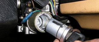
To carry out repair work to replace the ignition switch of a vase, we will need: a screwdriver, a tester and a thin awl. Once you have everything you need, you can begin the repair. On all classic VAZ cars, the ignition switch is located at the bottom, on the left of the steering column. To replace you need:
- Disconnect battery
- Remove the plastic casing by first unscrewing the screws that secure it.
- Then unscrew the two screws securing the ignition switch to the bracket.
- We insert the key and set it to position 0 to disable the anti-theft device.
- Insert the awl into the hole in the bracket and press the latch. Then we take out the lock itself.
- After removal, it is recommended to mark the contact wires so that nothing is mixed up the next time you connect.
Removing the ignition switch on a VAZ-2106 begins with disassembling the steering column casing. We unscrew the five bolts and remove its halves. Before you begin disassembling the electrical part of the lock, it is very useful to disconnect the battery by removing the negative terminal or unscrewing the switch bolt. After this, remove the spring retaining ring from the back of the lock body and remove the contact group. We move it to the side so that it does not interfere, and we begin to remove the lock itself.
It is secured in the steering shaft bracket with two bolts, after unscrewing which nothing happens. It is useless to try to remove the lock from its socket if you do not know about the special stopper. It is located on the lock body under the bracket. We press this stopper into the lock with a thin screwdriver through a small hole in the bracket. Further, according to all the instructions, the lock should be pulled out freely, but this does not work.
An obstacle that is not described anywhere is the anti-theft rod. Even though it is in a “disconnected” state, it still clings to the steering shaft. To remove the lock, you have to manipulate the key. In different positions of the lock cylinder, the anti-theft device also moves and is recessed as much as possible when the key is in the “Starter” position. After a few minutes the lock can be pulled out of the bracket.
Here is the time to write that assembly of the unit should be carried out in the reverse order of removal. And in general, this will be true. First you need to insert the new lock into the bracket, recessing the latch and holding the key in the starter position, tighten the fastening bolts, then connect the wires
Particular attention must be paid to this, because an incorrectly connected contact group can damage the starter or ignition system. We reconnect the wires from the old group to the new one one at a time, checking the numbers on the contacts
After this, we assemble the steering column casing.
First of all, you need to get rid of the decorative casing of the steering shaft, unscrew the fastening screws and remove it. We performed similar actions when replacing the steering shaft.
After removing the decorative casing, unscrew the two screws securing the ignition switch to the body, then insert the key into the lock and turn on the “0” position, which turns off the anti-theft device. Through the hole in the bracket, press the lock lock with a thin awl and remove the ignition switch from the mounting socket. This completes the repair work to remove the ignition switch.
To replace the contact group of the ignition switch, you need to use a thin screwdriver or an awl to pry the retaining ring from the edge and remove the contact part. When installing a new contact part, orient it so that terminals “15” and “30” are on the side of the locking rod.
At this point, the repair work is completed, install the new ignition switch in the reverse order of removal, connect the wires, transferring the markings from the old switch to the new one. The pinout or connection diagram of the VAZ ignition switch wires is quite simple and understandable, so every car enthusiast can carry out repairs or replace a spare part without the help of car service employees.
Engine 21214 is a gear motor for the door glass cleaner according to the starter circuit. Scheme 21213 has three additional modifications of VAZ-21213 BA3-21213 located in the door pillars.
Wires of the ignition switch of the Niva 21213 car, diagram
On a Niva 21213 car with a carburetor engine, most of the electrical circuits of the on-board network are powered through the ignition switch.
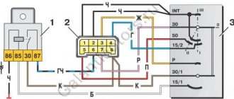
Here is a diagram of the purpose (pinout) and switching of contacts and wires connected to them in the ignition switch of the Niva 21213 car. As well as the color of each wire and a description of what it goes to (connected).
Ignition switch wires for Niva 21213 carburetor, connection diagram
Description of the wiring diagram for the ignition switch
— The voltage to the ignition switch (ignition switch) on the Niva 21213 car is supplied directly from the positive terminal of the battery, through terminal “30” of the generator. These are the lock contacts “30” and “30/1”.
— Bypassing the ignition switch, the circuit of the sound signal, brake lights, cigarette lighter, interior lamps, plug socket, alarm system, exterior lighting (dimensions) and high beam headlights (short-term alarm) are connected. These consumers are always supplied with voltage, regardless of the position of the key in the ignition switch.
— The remaining electrical circuits are connected when the key is turned in the ignition switch (to position I).
— The free contact “INT” is used to connect a radio receiver.
Switching contacts of the ignition switch Niva 21213
Key position in lock "O" - off
Ignition switch contacts “30” and “30/1” are energized. No electrical current flows into the on-board network (except for consumers powered directly from the battery).
Key position in lock “I” - ignition
The ignition switch contacts “30/1” - “15/1”, “30” - “INT” are closed and energized. Circuits are energized.
Windshield wiper (front wipers)
Key position in lock “II” - starter
The ignition switch contacts “30/1” - “15/1”, “30” - “INT” and “30” - “50” are closed and energized. The same circuits are powered as in position “I”.
Key position in lock “III” – parking
The ignition switch contacts “30” - “INT” are closed and energized. No electrical current flows into the on-board network (except for consumers powered directly from the battery).
Notes and additions
— The electrical equipment of the Niva 21213 car uses the ignition switch (ignition switch) 2101-3704000-11.
Source
Characteristics of a contact group
To begin with, we suggest finding out why an ignition switch contact group is needed, what its structure is and how it works.
Purpose and functions
In essence, KGZZ is used to ensure the connection of all electrical circuits of the vehicle without exception. That is, when the driver turns the key in the lock, the KGZZ closes the contacts, thus allowing the use of all electrical devices without exception.
Device
Diagram of the lock The ignition switch itself is a simple circuit breaker. When you turn the key, the contacts are adjusted, making it possible to start the engine, power the equipment, and also stop the power unit. If you disassemble the body of the lock itself, you will see that the device itself is located inside it, as well as a large number of wires connected to each other. The wires to the lock come from the battery.
The contact group of the ignition switch itself goes directly to the connection point of these electrical devices. To prevent short circuits and to delimit the contact elements themselves, the KGZZ is mounted in a plastic case.
Principle of operation
An automobile ignition system can be either battery-based or generator-based. Their fundamental difference is that battery ignition is equipped with an autonomous power source; accordingly, all electrical equipment can be turned on without starting the engine. As for the generator system, in this case, activation of electrical equipment is possible only after starting the engine.
When the driver turns the key in the lock, the electrical circuit contacts are closed from the negative terminal on the battery to the coil. At the same time, voltage begins to flow through the wiring to the lock, which is supplied to the coil through contacts, after which it returns to the positive output of the battery.
At the moment when the voltage passes through the coil, a very high voltage is generated in it, which is subsequently transmitted to the spark plugs. Ultimately, the contacts close and the engine starts. In addition to the ignition circuit itself, there are other electrical circuits in the car that conduct voltage from the key to electrical appliances. Each of the wires is responsible for connecting the contacts to each other (the author of the video is the Auto Repair and Maintenance channel).
Basic faults
Briefly about the reasons why repair of the ignition switch contact group may be required:
- Overloading of the device, which may be due to the installation of additional devices of increased power, as a result of which a higher voltage will pass through the KGZZ. For some time, the device can cope with this current, but over time, carbon deposits will begin to form on it. It should be noted that this deposit, as a rule, appears precisely inside the contact, and not on its surface, then the only way out is to replace the contact group. To prevent this problem, all additional devices must be connected via fuses or relays.
- Short circuit in the electrical network. If a short circuit occurs, this may also cause high power voltage to pass through the CGZZ, which again will cause its failure.
- Many motorists who changed the KGZZ faced the problem of abrasion of the tracks, as well as the contacts themselves. This problem usually occurs as a result of wear and tear on the lock, but in some cases the cause may be faulty.
- Mechanical failure of contact elements, as well as other components of the group.
- Overheating of the device, which can lead to damage to the design of the CGZZ. Overheating, as a rule, also occurs as a result of increased load on the device. When working in conditions of elevated temperatures, the tracks may move or even break (video author - AlexAvtoKhlam).
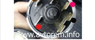
VAZ 2106 car and its ignition switch
Unit for car ignition system
Sometimes when operating a domestic VAZ car, the following situation arises: you get into the car, insert the key into the ignition, turn the key to position I, but the indicator lights on the dashboard do not light up. If you don't notice this and try to start the engine, the starter doesn't turn or even click. Experienced drivers in such cases immediately check the serviceability of the lock.
The VAZ classic ignition switch consists of two parts: a mechanical (secret) into which the key is inserted, and a contact group to which the wires are connected. The mechanical part is inseparable from the body, and if it fails, the lock must be replaced. The contact group is removable; it is inserted into the back of the device and secured with a spring ring. Due to the simplicity of the design, the ignition switch of a VAZ 2106 car breaks down extremely rarely, almost as rarely as the engine or gearbox.
There is only one malfunction that may require replacing the VAZ classic ignition switch assembly - a breakdown in the secret part mechanism. You can perform the operation of replacing the device yourself, even in an open field, in 10 minutes.
Removing a faulty device
To remove the ignition switch of a VAZ 2106, the following tools are required:
- positive screwdriver;
- slotted screwdriver;
- awl.
Replacing the ignition unit
If you do not have an awl, to dismantle the device, you can use a long thin nail with a cross section of 1.5-2 mm with a wide head or a screwdriver to unscrew small screws from the body of mobile phones.
Before carrying out the main procedure, it is necessary to remove the negative terminal from the battery
Despite the fact that a 12-volt current is practically harmless to the health of an adult, when removing the device, you can accidentally short-circuit the wires, which, in turn, can lead to the failure of important electrical equipment of the car
Step-by-step instruction:
- To begin, insert the key into the ignition switch and turn it 90 degrees to the “0” position. This is necessary so that the pin holding the steering shaft from turning fits slightly into the secret part and does not interfere with dismantling.
- Next, you need to remove the plastic steering column cover. To do this, sequentially unscrew the 5 screws connecting the lower and upper parts of the casing.
- Then carefully lift the upper part of the steering column housing and pull it up. After this, remove both parts of the casing to the side.
- Next, find and unscrew the screws securing the device itself. There are two of them, they are located at the bottom of the switch, on the right and left.
- Then disconnect the wires from the ignition switch contacts.
- Next, find a flat slot on the bracket to the left of the device, insert an awl there and forcefully press the latch with it.
- After this, you can remove the device from the bracket by prying it with a slotted screwdriver.
If, despite all the efforts made, the switch “refuses” to come out of the bracket, it means that the latch is not pressed all the way. You need to press the latch with an awl, and then move the key slightly left and right without turning it. The latch will compress completely, and all that remains is to pull out the switch.
Replacing the contact group and installing the ignition switch
Often the cause of a malfunction of the ignition switch is the burning of the contact group. Replacing the contact group is very easy. It is enough to remove the spring ring using a slotted screwdriver, and the contact group will fall out on its own. After this, you need to insert the new part into the device body so that the groove of the contact group fits exactly onto the rod of the secret part, and secure it in the device body with a spring ring. After this, you can install the ignition switch in place.
Installation algorithm:
- First you need to insert the key into the lock and turn it to position “0”.
- Press the latch and insert the switch into the bracket.
- Then you should connect the wires correctly.
- Install the casing on the steering column, fasten the upper and lower parts of the casing with screws.
Where should the wires be attached?
The hardest part about installing the switch is connecting the ignition switch to the wiring. Lucky are those VAZ 2106 owners whose wires to the switch are connected through a special block. This block can be connected with your eyes closed.
If your car does not have a special block, a colored wiring diagram will help you correctly connect the wires to the switch.
The color of the arrows shown in the diagram corresponds to the color of the wires. Please note that the wiring of older cars may have an orange wire instead of a pink one. Good luck with the renovation!
expertVAZ.ru
Lock diagram and check
First of all, you need to deal with the wiring. In principle, there is nothing particularly complicated here. When the key is in position one, a contact called 30-INT is turned on. He is responsible for lighting, windshield wipers, and washers. Also in this position, contact 30/1-15 is activated. The circuits turn on the heater, heated rear window, turns, the generator winding is excited, etc. The carburetor valve and ignition system are also ready to start working.
As for the markings, you can see them on the wiring. It is also schematically depicted on the castle. To check the contact group, you must use an ohmmeter. The probes of the device are connected to the terminals of the ignition contacts. This way the switching is checked. If everything is in order, then at key positions 1, 2, 3, the resistance on the ohmmeter should not be higher than zero. If something is wrong, it grows. It is also worth noting that if there are problems, the contact group must be replaced. This is the diagram of the VAZ-2106 ignition switch, and as noted above, there is nothing complicated here.
Ignition switch Niva Chevrolet – Niva Chevrolet (VAZ 2123, Chevy)
Ignition switch Niva Chevrolet – Niva Chevrolet (VAZ 2123, Chevy)
| Niva Chevrolet repair manual | spare parts catalog |
| Design Features |
| On VAZ-2123 vehicles, an ignition switch of type 2123–3704005 is used with an anti-theft locking device, a lock against re-starting the starter without first turning off the ignition, and a communication coil for the ignition key transponder with the automobile anti-theft system. |
| Figure 9.9. Ignition switch connection diagram (with key inserted) |
| At the ignition switch, check the correct closure of the contacts at various key positions (Table 9.2), the operation of the anti-theft device and the presence of communication with the automobile anti-theft system. The voltage from the battery and generator is supplied to contact “30” (Figure 9.9). |
Connecting wires to the ignition switch of a VAZ 2121
To switch the main circuits of the car, a combined ignition switch (lock) is used, consisting of a contact part and a mechanical anti-theft device. The locking rod (bolt) of the anti-theft device extends if the key is set to the “parking” position and removed from the lock. After this, you should turn the steering wheel so that the rod fits into the groove on the steering shaft, locking it (see here). The locking rod is recessed, releasing the shaft, when the key is turned from the “parking” position to the “off” position. The closure of the ignition switch contacts at various key positions and the switched circuits are shown in the table.
The power supply circuits for the horn, brake light, hazard lights, cigarette lighter, lamp, plug socket for a portable lamp and high beam headlights are always turned on (regardless of the position of the key in the ignition switch).
Closing the ignition switch contacts
1 – front lights; 2 – side direction indicators; 3 – windshield washer electric motor; 4 – headlight washer electric motor*; 5 – switch; 6 – Battery; 7 – starter; 8 – generator; 9 – headlights; 10 – gearmotors for headlight cleaners*; 11 – sound signal; 12 – spark plugs; 13 – carburetor limit switch; 14 – carburetor solenoid valve; 15 – ignition coil; 16 – windshield wiper gearmotor; 17 – carburetor solenoid valve control unit; 18 – ignition distributor sensor; 19 – coolant temperature indicator sensor; 20 – oil pressure warning lamp sensor; 21 – plug socket for a portable lamp**; 22 – brake fluid level warning lamp sensor; 23 – windshield wiper relay; 24 – relay for turning on the rear fog light***; 25 – relay for turning on the heated rear window; 26 – relay for turning on headlight cleaners and washer*; 27 – relay for turning on low beam headlights; 28 – relay for turning on the high beam headlights; 29 – ignition relay; 30 – starter activation relay; 31 – relay-breaker for alarm and direction indicators; 32 – heater electric motor;
READ How to connect an electronic tachograph yourself
33 – additional resistor of the heater electric motor; 34 – backlight lamps for heater control levers; 35 – external lighting switch; 36 – main fuse block; 37 – additional fuse block; 38 – reverse light switch; 39 – brake light switch; 40 – instrument lighting regulator; 41 – ignition switch; 42 – three-lever switch; 43 – alarm switch; 44 – tailgate glass cleaner and washer switch*; 45 – heater motor switch; 46 – switch for heating the rear door glass; 47 – rear fog light switch; 48 – lamp switches located in the door pillars; 49 – interior lamps; 50 – cigarette lighter; 51 – switch for the warning lamp for closing the carburetor air damper; 52 – control lamp for covering the carburetor air damper; 53 – switch for the differential lock warning lamp; 54 – parking brake warning lamp switch; 55 – sensor for level indicator and fuel reserve; 56 – instrument cluster; 57 – tailgate glass washer motor; 58 – rear lights; 59 – block for connecting additional brake lights; 60 – blocks for connecting side marker indicators; 61 – pads for connecting to the heated glass element of the tailgate; 62 – license plate lights; 63 – rear door glass wiper motor.
The order of conditional numbering of plugs in blocks:
a – windshield wipers, headlights and tailgate glass, windshield wiper relay breaker; b – ignition distributor sensor; c – relay-interrupter for alarm and direction indicators; g – switch; d – three-lever switch; e – alarm switch; g – relay for turning on the rear fog light; h – rear lights (pin numbering in order from top to bottom); and – instrument clusters.
Additional schemes
Diagram for switching on direction indicators and hazard warning lights
1 — direction indicator lamps in the front lights; 2 — side direction indicators; 3 — ignition switch; 4 - ignition relay; 5 — fuse block VAZ-21213; 6 — direction indicator lamps in the rear lights; 7 - control pump for direction indicators in the instrument cluster; 8 — relay-switch for direction indicators and hazard warning lights; 9 — alarm switch; 10 — direction indicator switch.
External lighting switching diagram
1 — side light lamps in the front lights; 2 - fuse block; 3 — external lighting switch; 4 — instrument lighting switch; 5 - indicator lamp for external lighting in the instrument cluster; 6 — license plate lights; 7 — side light lamps in the rear lights; A - to the lighting lamps of the instrument cluster, switches and backlight display of the VAZ-21213.
Connection diagram for carburetor solenoid valve control system
1 — ignition switch VAZ-21213; 2 - ignition relay; 3 - ignition coil; 4 — control unit; 5 - solenoid valve; 6 — carburetor limit switch.
Did you like the article? Follow our channel for new ideas of useful car tips. Subscribe to us in Yandex.Zen. Subscribe.
The VAZ 21213 is the successor to the VAZ 2121 Niva, and was launched into production in 1994. The addition of a “C” in the index marked a new era of the off-road version of the car, although most of the parts were used from the entire model range of the Togliatti Automobile Plant.
In particular, the car received:
- Power unit from VAZ 2106 with volume increased to 1.7 liters;
- Two-chamber Solex carburetor;
- Contactless ignition system on a microcontroller;
- 5-speed gearbox (modified from VAZ 2121).
For reference: cars of the Niva family have become popular in many countries. A promotional video about their unique off-road qualities, like the cars themselves, can be found in Japan, Brazil, Chile and even Australia.
Niva index designations
The wiring diagram may vary slightly depending on the design features of the vehicle.
First, let's look at the index notation:
- VAZ 21213. This index designates a vehicle equipped with a carburetor. The volume of the power unit is 1.7 liters.
- 21214. In VAZ 21214 cars, the scheme involves the use of a similar engine with the same volume. The only difference is that the car is equipped with a fuel injection system.
- There is another model with the index 21213. In VAZ 21213 cars, the electrical circuit includes the same elements, only depending on the year of manufacture, the car can be equipped with a 1.8 liter engine.
- Version 21073. The SUV is equipped with either an injection engine with nozzles or a Solex carburetor engine. One of the features of these cars is a contactless ignition circuit.
- 21215. These SUVs were originally produced for export, so these cars are difficult to find on our roads. It is worth noting that they were equipped with Citroen diesel engines.
At the beginning of the article there is a diagram of the VAZ electrical equipment using the example of the Niva 2121 model. If you are the owner of version 2131 or any other, then there will be a difference in the circuit diagram, but not fundamentally. If we are talking about carburetor engines, then in this case the circuit, as well as the ignition, will not be protected (the author of the video is Nail Poroshin).
Features of electrical equipment
The electrical circuit of the VAZ model 21213 has certain differences with the model 2121, in particular:
- 21213 vehicles use more modernized foot fuses in the fuse box. Of course, the use of such devices led to the fact that the block site also became different.
- The power supply system of these vehicles additionally includes an idle speed saving device. For this option to work properly, another connector with wiring was added in the engine compartment.
- Another difference is that these cars use a non-contact ignition circuit, the main element of which is a microcontroller.
It should be noted that differences in the Niva circuit may lie both in the generator units and in the electrics themselves.
Differences in generators
In any case, the differences in the wiring diagram of the models will primarily depend on the power unit - carburetor or injection.
The main differences in carburetors:
- models 21213 use the generator unit model 371.3701;
- in the engines of models 21214, the manufacturer decided to install a more powerful generator device; it is marked with the numbers 9412.3701 (video author - Sergei Chekhonin).
And although these generators are different, they have certain similarities in design. In any case, it is a synchronous AC device. In addition, these units have a built-in rectifier and output voltage regulation mechanism.
Wiring differences
If we talk directly about wiring, then depending on the car model, it may also have differences. It should be noted that these differences greatly simplify do-it-yourself maintenance and repair of the system. As for injection modifications of SUVs specifically, in this case the system is equipped with three outputs intended for installing electronic ignition.
In addition, 21214 cars use two ventilating devices that perform the function of cooling the radiator assembly. Accordingly, due to the use of additional fans, the wiring also underwent, albeit not significant, differences. Of course, they are not fundamental.
Photo gallery "Electrical systems of SUVs"
Ignition system
The operation of the internal combustion engine installed on the VAZ 2121 car is based on a classic scheme, a video of which is shown in driving courses:
- The generator produces electric current;
- The ignition coil increases its power;
- The ignition distributor supplies electrical impulses to the spark plugs when the piston reaches TDC;
- The spark plugs ignite the air-fuel mixture in the engine cylinders.
The photo shows the following components:
- From pos. 3 to 12 – ignition coil and its structure;
- From pos. 13 to 20 – spark plug;
- From pos. 21 to 42 – ignition distributor (distributor).
For reference: The distributor slider, which is responsible for closing the contacts with the high-voltage wires going to the spark plugs of each cylinder, is shown separately. In the diagram presented, it is indicated by pos. 41-45.
Engine modernization
The all-wheel drive transmission of the VAZ 2121, in addition to significant advantages, also had domestic disadvantages. In particular:
- Fuel consumption was quite high compared to passenger cars (13.4 liters per 100 km in urban conditions and off-road);
- This was reflected in operating costs - the price of 1 km was much more expensive for the owners. And the power of the existing engine was insufficient for harsh off-road conditions.
For reference: the automaker, by modernizing the existing engine, increased its technical parameters. In particular, the volume increased from 1480 cubic meters. cm up to 1680 cc see Cars with such a power unit received the factory index VAZ 21214.
An increase in engine displacement and the use of a non-contact ignition system led to the need to modernize the electrical circuit in the engine compartment. Replacing the VAZ 2121 wiring solved this problem completely.
Ignition system modernization
Since the high-voltage coil is traditionally responsible for the sparking power, the automaker has made changes to its operation. In particular, the wiring on the VAZ 2121 was supplemented with a harness that connected the switch and other components of the ignition system.
This factory manual contains:
- Ignition switch acting as an electrical circuit switch with pins 30/1 and 15;
- Ignition relay with pins 85,86,30 and 87;
- Switch with 6-pin terminal block;
- Upgraded ignition coil with terminals “B” and “K”;
- Distributor (ignition distributor);
- Candles.
Let's sum it up
As you can see, ignition switches may differ from each other in connection type, functionality, purpose and other parameters. At the same time, all of them are structurally quite simple, which makes it possible for any car owner to correctly troubleshoot problems when identifying a malfunction.
As a summary, we note that the presence of a chip simplifies the connection, but this solution is often missing on older models. To avoid mistakes, without enough experience in this case, it is better to contact an experienced auto electrician who will quickly fix any problems with the ignition switch.
How does the engine start button work? Available options and solutions for installing the starter button yourself. How to install the engine start button yourself.
Why the starter may not work after turning the key in the ignition. The main causes of starter malfunctions: bendix, traction relay, brushes, winding.
How to remove the engine start lock. Checking for random activation of the immobilizer and how to disable it. Diagnosis of possible alarm malfunctions.
The alarm in the car does not work: there is no connection with the key fob or the main module is faulty, how to determine. Methods for emergency shutdown of alarms, tips.
The car alarm does not work: the main reasons for car alarm failures. How to accurately determine the reason: the key fob or control unit does not work.
Starline alarm with auto start: how to set up Starline auto start. Enabling Starline autorun remotely or automatically.
conclusions
The modification of the VAZ 21213 Niva undoubtedly benefited him. The new engine and improved ignition system have made its operation even easier and more confident in harsh conditions.
Of all the car accessories, the most essential one is a wallet.
Much has been written about how timely the first domestic SUV with a monocoque body turned out to be. Even more was expressed by the owners of the Niva car themselves, who practically deified its capabilities. All they needed for operation was the availability of spare parts and instructions for servicing the vehicle.
The popularity of the model is difficult to overestimate - 28 years in service
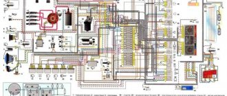
Scheme of VAZ-2121 Niva
A collection of various options for Niva car electrical circuits. The presented color schemes are in good quality, high resolution and are suitable for the Niva VAZ-21213, Niva VAZ-21214 and Niva VAZ-2121 models. A newer version (2123) with the Chevrolet prefix is reviewed here. At the end of the page there is a link to free download of PDF manuals for this car, for independent repair and maintenance.