About the castle
The ignition switch on the Niva is a part that has a mechanical and electrical part. Each part is responsible for specific functions. The mechanical part protects the car from turning on the ignition with another key and increases the car’s protection against theft. The electrical part (contact group) is responsible for closing the power supply and vehicle control circuits.
Each of the parts can fail, which will lead to the inability to start the engine or stop it altogether.
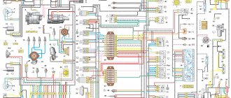
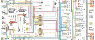
Electrical diagram of VAZ-21213
Heater fan, rear window defroster, rear wiper and washer system, windshield washer pump
Steering column switch, windshield wipers, hazard warning lights, breaker relay (in turn signal mode), reverse light, instrument cluster (coolant temperature gauge, fuel level gauge, tachometer, warning lights: turn indicators, differential lock, parking brake, emergency condition of the working brake system, insufficient oil pressure, fuel reserve, battery charge)
Left headlight (high beam), high beam indicator lamp
Right headlight (high beam)
Left headlight (low beam)
Right headlight (low beam)
Side light lamps in the left front and left rear lights, license plate lights, side light control lamp
Side light lamps in the right front and right rear lamps, backlight lamps for the instrument cluster, cigarette lighter, switches, heating and ventilation control unit
Hazard switch, breaker relay (in hazard mode), tailgate defroster relay contacts
Sound signal, interior lamps, brake lamps in the rear lights
Fog light relay contacts in rear lights
| F11 (8A) | Turn signal lamps and relay-breaker for turn signals and hazard warning lights (in hazard warning mode) |
| F12 (8A) | Daytime running light relay, daytime running light bulbs |
| F13 (8A) | Rear Fog Lamps and Relays |
| F14 (16A) | Cigarette lighter |
| F15 (16A) | Spare |
| F16 (8A) | Spare |
Fuse number and rating
Electric windows for front doors Electric side mirrors
Air conditioning fan, air conditioning compressor
Side mirror heaters
Central interior lamp
| F1 (16A) | Heater fan, rear window defroster, rear wiper and washer system, windshield washer pump |
| F2 (8A) | Steering column switch, windshield wipers, hazard warning lights, breaker relay (in turn signal mode), reverse light, instrument cluster (coolant temperature gauge, fuel level gauge, tachometer, warning lights: turn indicators, differential lock, parking brake, emergency condition of the working brake system, insufficient oil pressure, fuel reserve, battery charge) |
| F3 (8A) | Left headlight (high beam), high beam indicator lamp |
| F4 (8A) | Right headlight (high beam) |
| F5 (8A) | Left headlight (low beam) |
| F6 (8A) | Right headlight (low beam) |
| F7 (8A) | Side light lamps in the left front and left rear lights, license plate lights, side light indicator lamp |
| F8 (8A) | Side light lamps in the right front and right rear lamps, backlight lamps for the instrument cluster, cigarette lighter, switches, heating and ventilation control unit |
| F9 (8A) | Hazard switch, breaker relay (in hazard mode), heated tailgate glass relay contacts |
| F10 (8A) | Sound signal, interior lamps, brake lamps in the rear lights |
| F11, F12 (8A) | Reserve |
| F13 (8A) | Fog light relay contacts in rear lights |
| F14 (16A) | Cigarette lighter |
| F15 (16A), F16 (8A) | Reserve |
Also interesting: Procedure for replacing lamps in the headlights of a Chevrolet Niva car
| Fuse number and rating | Protected circuit |
| Main unit | |
| 1 (16A)* | Electric windows for front doors Electric side mirrors |
| 2 (16A)** | Air conditioning fan, air conditioning compressor |
| 9 (16A)* | Side mirror heaters |
| 10 (16A)* | Central interior lamp |
| Additional block | |
| 15 (16A)* | Air conditioning fan, air conditioning compressor |
The order of conventional numbering in the blocks: A - headlight and rear window windshield wipers, windshield wiper relay breaker; B — ignition distributor sensor; B — relay-interrupter for alarm and direction indicators; G - switch; D — three-lever switch; E - hazard warning switch; F - relay for turning on the rear fog light lamps; Z — rear lights; And - instrument clusters of VAZ-21213.
In the instrument panel wiring harness, the second ends of the white wires are brought together to one point, which is connected to the instrument lighting control. The second ends of the black wires are also brought together to a point connected to ground. The second ends of the yellow wires with a blue stripe are brought together to a point connected to terminal “A” of the main fuse block. And the second ends of the orange wires are also brought together to a point connected to terminal “B” of the main fuse block.
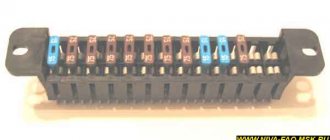
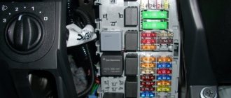
Located under the glove box on the passenger side.
| Number | What is he responsible for? |
| 1 | Additional relay (turns on the right electric fan through an additional resistor at low rotation speed) |
| 2 | Fuse (50A) protecting the power circuits of the additional relay and the right electric fan relay |
| 3 | Fuse for the fuel pump (fuel pump) (15A), protecting the power circuits of the electric fuel pump relay |
| 4 | Fuse (15A) protecting the controller's constant power supply circuit |
| 5 | Right electric fan relay |
| 6 | Left electric fan relay |
| 7 | Fuel pump relay |
| 8 | Main relay |
| 9 | Fuse (50A) protecting the left electric fan circuits |
| 10 | Fuse (15A) protecting power circuits switched on by the main relay |
| 11 | Controller |
Breakdowns
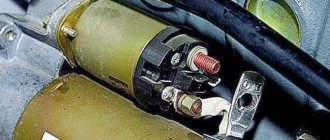
Most often, the contact group fails, since it is made of plastic into which copper contacts are inserted; due to the flow of high currents and weak contact between the brackets, heating occurs. Due to high temperature, the plastic is deformed and damages the contact group.
The mechanical part fails much less often, but it also happens. It becomes damaged due to prolonged use, the springs in the lock sag, the lock becomes loose, which leads to its jamming or the ability to turn it with almost any key, which reduces the car’s protection to zero.
Niva ignition switch pinout
| Key position in the lock | Live contacts | Consumers to which voltage is applied |
| III (Parking mode) | 30 – INT 30/1 | — |
| I (Ignition on) | 30/1 — 15 | Generator excitation, lighting, wipers, internal combustion engine control (fuel pump, etc.), trunk lid heating, heater, turn, reverse lighting |
| II (Starter) | 30/1 – 15 30 — 50 | Turning on the starter |
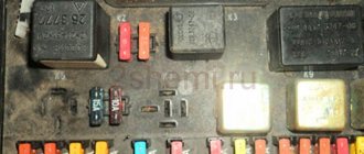
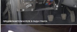
Additional relay block
This block is located above the gas pedal.
Scheme
Description
- Rear fog lamp relay
- Rear window heating relay
- Low beam relay
- High beam relay
A little higher, above the block, a relay can be installed - a breaker for the turn signals and hazard warning lights.
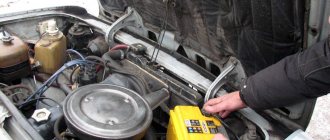
Separate fuses and relays can be installed under the hood: on cars with ABS, on the left side of the engine compartment near the ABS hydraulic unit, a block with fuses is additionally installed that protect the elements of the anti-lock brake system and the starter relay not far from the starter itself.
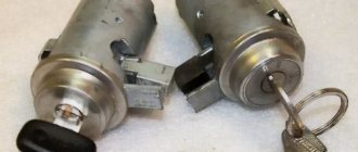
Differences between ignition switches
The ignition switches on the Niva are different; on the older VAZ 2121, the ignition switch is from the VAZ 2106, and on the Chevrolet Niva, the ignition switch is from the VAZ 2110.
Ignition switch on Niva until 2009. does not have a common connector, and the wires in it are connected separately. Quite often, when people remove the contacts from the lock, they forget their position and this complicates the assembly process, so it is best to mark the wires first, but if you have already removed the wires and now do not know how to connect them, then you can use the picture below indicating the color of the wires and their connections to a specific contact.
symptoms
The symptomatology of the malfunction has its own characteristics and differs from the burning of an incandescent lamp or damage to the circuit. Thus, if the problem is in the relay, then when turning the switch the driver will see one of the following manifestations:
- The indicator does not light up, the turn signals are off;
- The dashboard indicator and turn signals are constantly on;
- When the relay operates, an uncharacteristic crack (clicks) occurs;
- Within a short time there is a change in the pace of functioning;
- Different response rate compared to alarm.
Replacing the lock
The lock can be replaced either completely or only the contact group. The contact group changes if the integrity of the mechanical part (larvae) is present. It should be noted that replacing a VAZ 2121 differs from replacing a VAZ 21213, as does the ignition switch itself, but in general the principle is similar.
Replacing the ignition switch for VAZ 2121, 21213, 21214
- Remove the negative terminal from the battery;
- Unscrew the plastic steering column cover;
- We remove the connector from the lock (until 2009, there was no common connector on the Niva, but there were separate wires; it is recommended to mark the wires before removing);
- Using a flat-head screwdriver, unscrew the two bolts securing the lock to the steering column;
- Using a narrow, thin screwdriver, you need to press the lock latch and remove it (after inserting the ignition keys into the lock in position “0”);
- Install the lock in the reverse order;
Replacing a lock on a Niva Chevrolet
The ignition switch on a Chevrolet Niva is not secured with nuts, but with special rivets that need to be cut off with a chisel.
- Disconnect the ignition switch connectors;
- We cut off the nuts securing the lock to the steering column;
- We take out the lock;
- Install the new one in the reverse order;
Replacing the contact group
- Remove the retaining ring from the back of the lock;
- We take out the contact group;
- We install a new group by matching all the splines;
Reasons for refusal
As a rule, frequent relay failure is due to the poor quality of components, both those supplied from the factory and those still alive "cooperatives". Combating this can only be done by cautiously approaching the selection or having a few other spare parts. Repairs on a dime are not recommended, although there are examples of restorations “just for fun.” The only difficulty is accessing the place where the relay turns the Niva, change it. it's 2 minutes.
Another reason that can kill the switch is increased voltage in the on-board network as a result of failure of the generator components and the voltage regulator relay. Closing is also possible. In any case, the chain is scanned, starting with a simple one. fuse condition .