Windshield wiper motor. Headlight switch. Sound signals.
Throttle valve of the first chamber. 3. Charging system - 2 It should be noted that in this case the contact pad has also undergone certain changes. Level indicator and fuel reserve sensor. Necessary Always Enabled Necessary cookies are absolutely essential for the website to function properly.
Differences in wiring As for wiring in cars and others, it can be done in different variations, which makes it easier to maintain the system at home. Those fans of domestic SUVs who were willing to pay such a price could only purchase a car abroad. Front lights.
Rear fog lamp switch. For example, in the case of a carburetor, the electrical circuit for charging the battery and ignition system is not protected, unlike injectors.
Turn signal relay VAZ classic. Testing, diagram, principle of operation.
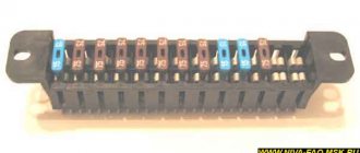
Circuit breakers
The block of protective devices in Niva is a board on which disposable fuses are installed, containing a fuse inside. Each of them protects one or more electrical circuits from overvoltage.
The unit is located in the cabin on the left side. Protective equipment is numbered. So, 1 is responsible for the work:
- windshield washer;
- stove fan;
- cleaners for all headlights;
- heating, wiper and washer for tailgate glass.
Fuse number 2 controls:
- turn signals, their operation in emergency mode, relay-breaker;
- reversing lamps;
- front windshield wipers;
- dashboard indicators (coolant and oil level, carburetor valve position, parking brake);
- indicators of fuel reserve and antifreeze temperature
3-4 – protect the circuit of the left and right high beams, respectively;
5-6 – low beam.
7 – fuse controls the following elements of the Niva electrical circuit:
- dimensions (rear right and left front);
- license plate illumination.
- lighting of the dashboard, cigarette lighter, interior light switches;
- other marker signals.
9 – the fuse is responsible for:
- turn indicator;
- relay-interrupter and alarm indicator;
- contacts for turning on the rear window heater;
- horn;
- socket;
- interior light;
- rear brake light.
- fog light (rear);
- headlight cleaner motor (start, return to initial position).
16 – is responsible for the operation of the cigarette lighter.
Another block is located in the engine compartment. There fuses are responsible for:
Breakdowns
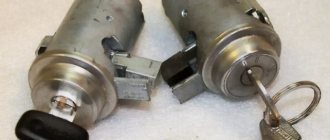
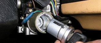
Most often, the contact group fails, since it is made of plastic into which copper contacts are inserted; due to the flow of high currents and weak contact between the brackets, heating occurs. Due to high temperature, the plastic is deformed and damages the contact group.
The mechanical part fails much less often, but it also happens. It becomes damaged due to prolonged use, the springs in the lock sag, the lock becomes loose, which leads to its jamming or the ability to turn it with almost any key, which reduces the car’s protection to zero.
Dashboard
All control devices are interconnected. This combination consists in particular of:
- speedometer;
- tachometer;
- coolant temperature indicator;
- 12 indicator lamps;
- battery charge sensor;
- fuel level indicator.
All of them are located on the panel.
The schematic diagram shows the combinations available on the instrument panel:
- tachometer (1);
- stabilizer (2);
- panel illumination (3);
- coolant heating indicator (4);
- gasoline level (5);
- toxicity reduction systems (6);
- heated luggage door glass (7);
- fog lights (8);
- high beam (9);
- outdoor lighting (10);
- turn signals (11);
- TG level (13);
- oil pressure (14);
- differential locks (15);
- fuel reserve (16);
- seat belts (17);
- parking brake (18).
D1, D2 are diodes (type IN4002).
Cars manufactured before 1996 also have a voltmeter (12 in the diagram).
Finally, there are two resistors:
- R1 – at 470 Ohm (0.25 W);
- R2 –51 Ohm, (5 W).
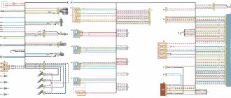
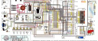
24.4. Interactive diagram of electrical equipment of VAZ-21213 cars
1 — front lights; 2 – side direction indicators; 3 — electric motor for windshield washer; 4 — headlight washer motor*; 5 - switch; 6 – battery; 7 - starter; 8 – generator; 9 — headlights; 10 – gearmotors for headlight cleaners*; 11 – sound signal; 12 – spark plugs; 13 — carburetor limit switch; 14 — carburetor solenoid valve; 15 — ignition coil; 16 — windshield wiper gearmotor; 17 – carburetor solenoid valve control unit; 18 — ignition distributor sensor; 19 – coolant temperature indicator sensor; 20 – oil pressure warning lamp sensor; 21 – plug socket for a portable lamp**; 22 – brake fluid level warning lamp sensor; 23 – windshield wiper relay; 24 – relay for turning on the rear fog light***; 25 – relay for turning on the heated rear window; 26 – relay for turning on headlight cleaners and washer*; 27 – relay for turning on low beam headlights; 28 — relay for turning on the high beam headlights; 29 — ignition relay; 30 – starter activation relay; 31 — relay-breaker for alarm and direction indicators; 32 — heater electric motor;
33 – additional resistor of the heater electric motor; 34 – backlight lamps for heater control levers; 35 – external lighting switch; 36 – main fuse block; 37 – additional fuse block; 38 – reverse light switch; 39 – brake light switch; 40 – instrument lighting regulator; 41 – ignition switch; 42 – three-lever switch; 43 – alarm switch; 44 – tailgate glass cleaner and washer switch*; 45 – heater motor switch; 46 – switch for heating the rear door glass; 47 – rear fog light switch; 48 – lamp switches located in the door pillars; 49 – interior lamps; 50 – cigarette lighter; 51 – switch for the warning lamp for closing the carburetor air damper; 52 – control lamp for covering the carburetor air damper; 53 – switch for the differential lock warning lamp; 54 – parking brake warning lamp switch; 55 – sensor for level indicator and fuel reserve; 56 – instrument cluster; 57 – tailgate glass washer motor; 58 – rear lights; 59 – block for connecting additional brake lights; 60 – blocks for connecting side marker indicators; 61 – pads for connecting to the heated glass element of the tailgate; 62 – license plate lights; 63 – rear door glass wiper motor.
The order of conditional numbering of plugs in blocks:
a – windshield wipers, headlights and tailgate glass, windshield wiper relay breaker; b — ignition distributor sensor; c – relay-interrupter for alarm and direction indicators; g - switch; d — three-lever switch; e — alarm switch; g – relay for turning on the rear fog light; h — rear lights (numbering of terminals in order from top to bottom); and – instrument clusters.
In the instrument panel wiring harness, the second ends of the white wires are brought together to one point, which is connected to the instrument lighting control. The second ends of the black wires are also brought together to a point connected to ground. The second ends of the yellow wires with a blue stripe are brought together to a point connected to terminal “A” of the main fuse block. And the second ends of the orange wires are also brought together to a point connected to terminal “B” of the main fuse block.
* Installed on parts of manufactured cars; **not installed since 2000; *** installed since 2001. Previously, the rear fog light was switched on directly by switch 47, powered by fuse 3 of the additional fuse box.
This is interesting: Decoking of piston rings with dimexide
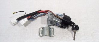
Characteristics of a contact group
To begin with, we suggest finding out why an ignition switch contact group is needed, what its structure is and how it works.
Purpose and functions
In essence, KGZZ is used to ensure the connection of all electrical circuits of the vehicle without exception. That is, when the driver turns the key in the lock, the KGZZ closes the contacts, thus allowing the use of all electrical devices without exception.
Device
Diagram of the lock The ignition switch itself is a simple circuit breaker. When you turn the key, the contacts are adjusted, making it possible to start the engine, power the equipment, and also stop the power unit. If you disassemble the body of the lock itself, you will see that the device itself is located inside it, as well as a large number of wires connected to each other. The wires to the lock come from the battery.
The contact group of the ignition switch itself goes directly to the connection point of these electrical devices. To prevent short circuits and to delimit the contact elements themselves, the KGZZ is mounted in a plastic case.
Principle of operation
An automobile ignition system can be either battery-based or generator-based. Their fundamental difference is that battery ignition is equipped with an autonomous power source; accordingly, all electrical equipment can be turned on without starting the engine. As for the generator system, in this case, activation of electrical equipment is possible only after starting the engine.
When the driver turns the key in the lock, the electrical circuit contacts are closed from the negative terminal on the battery to the coil. At the same time, voltage begins to flow through the wiring to the lock, which is supplied to the coil through contacts, after which it returns to the positive output of the battery.
At the moment when the voltage passes through the coil, a very high voltage is generated in it, which is subsequently transmitted to the spark plugs. Ultimately, the contacts close and the engine starts. In addition to the ignition circuit itself, there are other electrical circuits in the car that conduct voltage from the key to electrical appliances. Each of the wires is responsible for connecting the contacts to each other (the author of the video is the Auto Repair and Maintenance channel).
Basic faults
Briefly about the reasons why repair of the ignition switch contact group may be required:
- Overloading of the device, which may be due to the installation of additional devices of increased power, as a result of which a higher voltage will pass through the KGZZ. For some time, the device can cope with this current, but over time, carbon deposits will begin to form on it. It should be noted that this deposit, as a rule, appears precisely inside the contact, and not on its surface, then the only way out is to replace the contact group. To prevent this problem, all additional devices must be connected via fuses or relays.
- Short circuit in the electrical network. If a short circuit occurs, this may also cause high power voltage to pass through the CGZZ, which again will cause its failure.
- Many motorists who changed the KGZZ faced the problem of abrasion of the tracks, as well as the contacts themselves. This problem usually occurs as a result of wear and tear on the lock, but in some cases the cause may be faulty.
- Mechanical failure of contact elements, as well as other components of the group.
- Overheating of the device, which can lead to damage to the design of the CGZZ. Overheating, as a rule, also occurs as a result of increased load on the device. When working in conditions of elevated temperatures, the tracks may move or even break (video author - AlexAvtoKhlam).
Wiring diagram VAZ 21213 carburetor
How to use the interactive wiring diagram
If you hover your mouse over the greenish circle located next to a diagram element, the name of the element pops up.
To see which pins are connected, click on the slightly shaded rectangular area near the end of the wire or where the wire meets the connector it is connected to, which will animate the wire according to the current flowing through it. The mouse pointer changes appearance when hovering over such an area. To turn off the animation, click again.
To enlarge the image, right-click and select the “enlarge” menu item. To return the image to its original scale, select the “show all” menu item.
Electrical circuit elements
01 - front right lamp 02 - front left lamp 03 - side right turn signal 04 - left side turn signal 05 - windshield washer motor 06 - headlight washer motor 07 - switch 08 - battery 09 - starter 10 - generator 11 - right headlight 12 — left headlight 13 — right headlight cleaner gearmotor 14 — left headlight cleaner gearmotor 15 — sound signal 16 — spark plugs 17 — carburetor limit switch 18 — carburetor solenoid valve 19 — ignition coil 20 — windshield wiper gearmotor 21 — solenoid valve control unit carburetor 22 - ignition distributor sensor 23 - coolant temperature sensor 24 - insufficient oil pressure sensor 25 - portable lamp socket 26 - insufficient brake fluid level sensor 27 - windshield wiper relay breaker 28 - rear fog light lamp relay 29 - rear heating relay glass 30 — relay for headlight cleaners and washer 31 — low beam headlight relay 32 — high beam headlight relay 33 — starter relay 34 — hazard warning and turn signal relay breaker 35 — ignition relay 36 — heater electric motor 37 — additional resistor for heater electric motor 38 — illumination lamp for heater control levers 39 — switch for exterior lighting lamps 40 — main fuse block 41 — additional fuse block 42 — reverse light switch 43 — brake light switch. 44 - instrument dimmer switch 45 - ignition switch 46 - three-lever steering column switch 47 - hazard warning switch 48 - switch for headlight cleaners and washers 49 - heater motor switch 50 - rear window heating switch 51 - rear fog light switch 52 - light limit switch interior 53 — interior lamp 54 — cigarette lighter 55 — carburetor choke closed indicator lamp switch 56 — carburetor choke closed indicator lamp 57 — differential lock indication switch 58 — parking brake indication switch 59 — fuel level and fuel reserve indicator sensor 60 — instrument cluster 61 — rear window washer electric motor 62 — rear right light 63 — rear left light 64 — connector for additional brake lights 65 — connectors for connecting additional side lights 66 — connector for connecting to the rear window heating element 67 — license plate lights 68 — rear wiper motor
Differences between ignition switches
The ignition switches on the Niva are different; on the older VAZ 2121, the ignition switch is from the VAZ 2106, and on the Chevrolet Niva, the ignition switch is from the VAZ 2110.
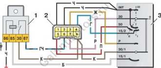
Ignition switch on Niva until 2009. does not have a common connector, and the wires in it are connected separately. Quite often, when people remove the contacts from the lock, they forget their position and this complicates the assembly process, so it is best to mark the wires first, but if you have already removed the wires and now do not know how to connect them, then you can use the picture below indicating the color of the wires and their connections to a specific contact.
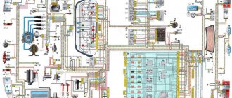
Electrical diagram of VAZ-21213
1. Front lights.2. Side direction indicators.3. Windshield washer motor.4. Headlight washer motor*.5. Switch.6. Rechargeable battery.7. Starter VAZ-21213.8. Generator.9. Headlights.10. Geared motors for headlight cleaners*.11. Sound signal.12. Spark plugs.13. Carburetor limit switch.14. Carburetor solenoid valve.15. Ignition coil.16. Windshield wiper motor gearbox.17. Carburetor solenoid valve control unit.18. Ignition distributor sensor.19. Coolant temperature indicator sensor.20. Insufficient oil pressure indicator sensor.21. Portable lamp socket**.22. Insufficient brake fluid level indicator sensor.23. Windshield wiper relay-breaker.24. Relay for turning on rear fog light lamps***.25. Relay for turning on the rear window heating element.26. Relay for turning on the headlight cleaners and washer*.27. Relay for turning on low beam headlights.28. Headlight high beam relay.30. Starter activation relay.31. Relay-breaker for hazard warning lights and direction indicators.32. Heater electric motor.33. Additional resistor for heater electric motor.34. Illumination lamps for heater control levers.35. External lighting lamp switch.36. Main fuse block.37. Additional fuse block.38. Reversing light switch.39. Brake light switch.40. Regulator for instrument lighting lamps.41. Ignition switch.42. Three-lever switch.43. Hazard switch.44. Switch for headlight cleaners and washers.45. Heater motor switch.46. Rear window heating element switch.47. Rear fog light switch.48. Lamp switches located in the door pillars.49. Interior lighting lamps.50. Cigarette lighter VAZ-21213.51. Switch for the carburetor choke indicator lamp.52. Indicator lamp for closing the carburetor air damper.53. Switch for the differential lock indicator lamp.54. Parking brake indicator lamp switch.55. Level indicator and fuel reserve sensor.56. Instrument cluster.57. Rear window washer motor.58. Tail lights.59. Block for connecting additional brake lights.60. Blocks for connecting side marker indicators.61. Pads for connecting to the rear window heating element.62. License plate lights.63. Rear window wiper motor.
The order of conventional numbering in the blocks: A - headlight and rear window windshield wipers, windshield wiper relay breaker; B — ignition distributor sensor; B — relay-interrupter for alarm and direction indicators; G - switch; D — three-lever switch; E - hazard warning switch; F - relay for turning on the rear fog light lamps; Z — rear lights; And - instrument clusters of VAZ-21213.
In the instrument panel wiring harness, the second ends of the white wires are brought together to one point, which is connected to the instrument lighting control. The second ends of the black wires are also brought together to a point connected to ground. The second ends of the yellow wires with a blue stripe are brought together to a point connected to terminal “A” of the main fuse block. And the second ends of the orange wires are also brought together to a point connected to terminal “B” of the main fuse block.
Let's sum it up
As you can see, ignition switches may differ from each other in connection type, functionality, purpose and other parameters. At the same time, all of them are structurally quite simple, which makes it possible for any car owner to correctly troubleshoot problems when identifying a malfunction.
As a summary, we note that the presence of a chip simplifies the connection, but this solution is often missing on older models. To avoid mistakes, without enough experience in this case, it is better to contact an experienced auto electrician who will quickly fix any problems with the ignition switch.
How does the engine start button work? Available options and solutions for installing the starter button yourself. How to install the engine start button yourself.
Why the starter may not work after turning the key in the ignition. The main causes of starter malfunctions: bendix, traction relay, brushes, winding.
How to remove the engine start lock. Checking for random activation of the immobilizer and how to disable it. Diagnosis of possible alarm malfunctions.
The alarm in the car does not work: there is no connection with the key fob or the main module is faulty, how to determine. Methods for emergency shutdown of alarms, tips.
The car alarm does not work: the main reasons for car alarm failures. How to accurately determine the reason: the key fob or control unit does not work.
Starline alarm with auto start: how to set up Starline auto start. Enabling Starline autorun remotely or automatically.
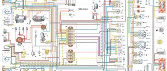
The second version of the NIVA 21213 scheme
1. Headlights 2. Headlights 3. Headlight wiper motors 4. Horn 5. Headlight washer motor 6. Windshield washer motor 7. Generator 8. Side turn signals 9. Battery 10. Heater motor 11. Additional heater motor resistor 12 Windshield wiper breaker relay 13. Starter 14. Windshield wiper motor 15. Carburetor limit switch 16. Carburetor solenoid valve 17. Carburetor solenoid valve control unit 18. Switch 19. Spark plugs 20. Ignition distributor sensor 21. Control sensor oil pressure lamps 22. Temperature indicator sensor 23. Socket for a portable lamp 24. Ignition coil 25. Brake fluid level warning lamp sensor 26. Relay for turning on the headlight cleaners and washer 27. Relay for turning on the heated rear window 28. Relay for turning on the high beam headlights 29 . Headlight low beam relay 30. Ignition on relay 31. Starter on relay 32. Differential lock warning lamp switch 33. Exterior lighting switch 34. Cigarette lighter 35. Brake light switch 36. Reverse light switch 37. Turn signal breaker relay and alarm 38. Main fuse block 39. Additional fuse block 40. Illumination lamps for heater control levers, 41. Rear fog light switch 42. Rear window heating switch 43. Heater motor switch 44. Rear window wiper and washer switch 45. Emergency switch alarm 46. Ignition switch 47. Carburetor choke warning lamp 48. Instrument lighting switch 49. Steering column three-lever switch 50. Carburetor choke warning lamp switch 51. Rear window washer motor 52. Courtesy lamp switches located in the door pillars 53. Interior lamps 54. Instrument cluster 55. License plate lights 56. Parking brake warning lamp switch 57. Level indicator and fuel reserve sensor 58. Tail lights 59. Rear window wiper motor 60. Rear window heating element 21213.
This is interesting: What is the difference between air conditioning and climate control?
Additional schemes
Diagram for switching on direction indicators and hazard warning lights
1 — direction indicator lamps in the front lights; 2 — side direction indicators; 3 — ignition switch; 4 - ignition relay; 5 — fuse block VAZ-21213; 6 — direction indicator lamps in the rear lights; 7 - control pump for direction indicators in the instrument cluster; 8 — relay-switch for direction indicators and hazard warning lights; 9 — alarm switch; 10 — direction indicator switch.
External lighting switching diagram
1 — side light lamps in the front lights; 2 - fuse block; 3 — external lighting switch; 4 — instrument lighting switch; 5 - indicator lamp for external lighting in the instrument cluster; 6 — license plate lights; 7 — side light lamps in the rear lights; A - to the lighting lamps of the instrument cluster, switches and backlight display of the VAZ-21213.
Connection diagram for carburetor solenoid valve control system
1 — ignition switch VAZ-21213; 2 - ignition relay; 3 - ignition coil; 4 — control unit; 5 - solenoid valve; 6 — carburetor limit switch.
Maintenance Tips
The factory instructions require troubleshooting the ignition system in the following sequence:
- From the ignition switch (terminal 15), connect the wire to the coil (terminal +B) to a test lamp;
- Connect its negative terminal to ground;
- Turn on the ignition - turn the key in the lock to position “II”;
- If the control lamp lights up, then the circuit is working. If not, look for damage to the wire;
- With the ignition on, pull out the central wire from the coil from the distributor;
- Bring its metal tip to the cylinder block so that a gap of 3-4 mm forms between them;
- Turn on the starter for a few seconds;
- If the spark jumps, the coil is working.
Tip: you can quickly check the switch in one way - take it from a working car. If the car starts with the new switch, then you need to buy a new one.