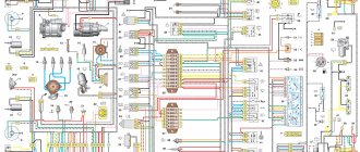
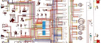
Electrical diagram of VAZ-2111 carburetor
1. block headlight; 2. front brake pad wear sensors; 3. fan motor activation sensor; 4. electric motor of the engine cooling system fan; 5. sound signal; 6. generator: 7. oil level sensor; 8. carburetor solenoid valve control unit; 9. heater controller; 10. recirculation valve switch; 11. illumination lamp for heater control levers; 12. switch; 13. carburetor limit switch; 14. oil pressure warning lamp sensor; 15. spark plugs; 16. carburetor solenoid valve; 17. coolant temperature indicator sensor; 18. ignition distributor sensor; 19. ignition coil; 20. VAZ-2111 starter; 21. heater fan electric motor; 22. additional resistor for the heater electric motor; 23. speed sensor; 24. reverse light switch; 25. micromotor gearbox for heater damper drive; 26. recirculation valve; 27. brake fluid level sensor; 28. blocks for connecting the rear window washer motor; 29. battery; 30. windshield washer motor; 31. washer fluid level sensor; 32. coolant level sensor; 33. windshield wiper gearmotor; 34. mounting block: 35. blocks for connecting the warning light harness; 36. outdoor lighting switch; 37. instrument cluster; 38. rear fog light switch; 39. fog light indicator lamp; 40. indicator lamp for heated rear window; 41. watch; 42. rear window heating switch; 43. steering column switch; 44. block for switching wires when installing headlights of a different type; 45. instrument lighting regulator; 46. ignition switch; 47. connectors for connecting the headlight cleaner wiring harness; 48. socket for a portable lamp; 49. lamp for individual interior lighting; 50. brake light switch; 51. interior lamp; 52. on-board control system unit; 53. fuel level indicator sensor; 54. hazard warning switch VAZ-2111; 55. driver's seat belt sensor; 56. cigarette lighter; 57. ashtray illumination lamp; 58. glove compartment lamp switch; 59. block for connecting the on-board computer; 60. glove box lighting lamp; 61. side direction indicators; 62. switches in the front door pillars; 63. switches in the rear door pillars; 64. parking brake warning lamp switch; 65. trunk lighting; 66. temperature sensor for the heating system; 67. external rear lights; 68. internal rear lights; 69. license plate lights; 70. rear window heating element; 71. block for connecting an additional brake light for VAZ 2111.
Wiring diagram for VAZ 2111 injector
- 1 – block headlight
- 2 – front brake pad wear sensors
- 3 – sound signal
- 4 – cooling system fan
- 5 – reverse light switch
- 6 – battery
- 7 – generator
- 8 – oil pressure warning lamp sensor
- 9 – oil level sensor
- 10 – spark plugs
- 11 – nozzles
- 12 – idle speed regulator
- 13 – electronic control unit blocks
- 14 – throttle position sensor
- 15 – crankshaft position sensor
- 16 – ignition module
- 17 – coolant temperature indicator sensor (for instrument cluster)
- 18 – starter
- 19 – diagnostic block
- 20 – coolant temperature sensor (for engine management system)
- 21 – speed sensor
- 22 – fuel pump activation relay
- 23, 35, 39 – fuses
- 24 – electric fuel pump
- 25 – micromotor gearbox for heater damper drive
- 26 – recirculation valve
- 27 – heater fan
- 28 – windshield washer pump
- 29 – washer fluid level sensor
- 30 – brake fluid level sensor
- 31 – coolant level sensor
- 32 – windshield wiper gear motor
- 33 – additional heater fan resistor
- 34 – injection system power supply relay
- 36 – adsorber purge valve
- 37 – mass air flow sensor
- 38 – relay for turning on the cooling fan
- 40 – external lighting switch
- 41 – knock sensor
- 42 – oxygen concentration sensor (heated lambda probe)
- 42* – CO potentiometer (installed on cars running on leaded gasoline; in this case, an oxygen concentration sensor is not installed)
- 43 – fog light indicator lamp
- 44 – indicator lamp for heated rear window
- 45 – fog light switch
- 46 – rear window heating switch
- 47 – instrument cluster
- 48 – mounting block
- 49 – fuel level sensor
- 50 – ignition switch
- 51 – instrument backlight brightness control
- 52 – steering column switch
- 53 – backlight lamp for heater control levers
- 54 – hazard warning switch
- 55 – electronic heater control unit; 56 – recirculation valve switch
- 57 – display unit of the on-board control system
- 58 – side direction indicators
- 59 – temperature sensor for the heating system
- 60 – interior lamp
- 61 – front interior lamp
- 62 – socket for a portable lamp
- 63 – electronic watch
- 64 – switches in the front door pillars
- 65 – switches in the rear door pillars
- 66 – glove box lighting lamp
- 67 – glove box lighting switch
- 68 – cigarette lighter
- 69 – ashtray lighting lamp
- 70 – brake light switch
- 71 – rear window heating element
- 72 – external rear lights
- 73 – internal rear lights
- 74 – license plate lamps
- 75 – trunk lighting lamp.
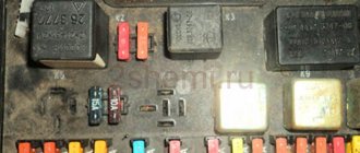
Designations of elements and malfunctions of the mounting block
If you can still somehow figure out the electrical circuit diagram, then the mounting block is a dark forest. All we know is the assignment of fuses, which can be found in any table. Some of the relays did not fit into the main mounting block for some reason and the engineers made a strategic decision to space some of the elements across the front panel. Thus, the main mounting block is located to the left of the driver, similar to the old fuse blocks. There is another small unit in the same niche, and another one is hidden in the center console. To figure out what was hidden where, let’s look at the relays that are in these three blocks.
The main block contains 6 relays, each of which has its own functions: these are the low-power lamp relay K1, the wiper drive relay K2, the hazard warning relays K3, K4 and K5 turn on the high and low beam, and the K7 relay starts the heated rear window. Behind the main block there is a second mounting block, which must be contacted in cases where there are problems with the power supply of the fan, fuel pump, ignition unit (these are three relays), and there you can also find the fuses of the ignition controller, speedometer sensor, oxygen mass flow sensor fuse , fuses for the heating sensor, purge valve, fuel pump and power system module. These fuses should be rated at 15 A. Everything that did not fit into these two blocks was hidden in the console - the fog lights and additional lighting relays, the immobilizer, the central locking.
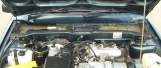
VAZ 2111 engine control circuit
- 1 — fragment of the mounting block.
- 2 — electric fan of the engine cooling system.
- 3 - status indicator of the car anti-theft system.
- 4 — control unit of the automobile anti-theft system.
- 5 — coolant temperature sensor.
- 6 — air flow sensor.
- 7 - throttle pipe.
- 8 - block connected to the throttle position sensor.
- 9 - block connected to the idle speed regulator.
- 10 – VAZ 2111 controller.
- 11 - block connected to the air conditioner wiring harness.
- 12 — oxygen sensor.
- 13 - knock sensor.
- 14 - crankshaft position sensor.
- 15 - speed sensor.
- 16 – adsorber.
- 17 - battery.
- 18 - main relay.
- 19 - block connected to the wiring harness of the anti-lock brake system.
- 20 — diagnostic block.
- 21 - main relay circuit protection fuse.
- 22 - controller protection fuse.
- 23 - fuse for protecting the electric fuel pump and its relay.
- 24 - relay for turning on the electric fuel pump.
- 25 — relay for turning on the electric fan.
- 26, 27 — blocks connected to the instrument panel wiring harness.
- 28 — ignition module.
- 29 - electric fuel pump with fuel level sensor.
- 30 - spark plugs.
- 31 – injectors.
Purpose of the plugs in block 26: 1 - to the low-voltage input of the tachometer in the instrument cluster; 3 - to the “Engine fault” lamp in the instrument cluster (from the controller); 4 - to the lamp switch located on the driver's door pillar; 5 - to the “Engine fault” lamp in the instrument cluster (supply “+” power); 6 — to the trip computer (fuel consumption signal); 7 - to the instrument cluster (vehicle speed signal 2111); 8 – to terminal “15” of the ignition switch (plug 4 of the switch block).
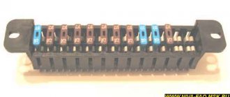
VAZ-2111 fuse block diagram
- 1 - ignition module
- 2 — speed, air flow, heating sensors
- 3 - fuel relays, pump, injectors
- 4 - fan
- 5 - fuel pump
- 6 - ignition
- F1 5 Lighting lamps: license plates, instruments, dimensions on the dashboard, left dimensions, trunk lighting
- F2 7.5 Low beam in the left headlight
- F3 10 High beam in the left headlight
- F4 10 Right front fog lamp
- F5 30 Door windows
- F6 15 Portable lamp, cigarette lighter
- F7 20 Radiator fan, sound signal
- F8 20 Heated rear window
- F9 20 Windshield washer and wiper
- F10 20 Reserve
- F11 5 Clearance on the right side
- F12 7.5 Low beam in the right headlight
- F13 10 High beam in the right headlight
- F14 10 Fog lamp, left
- F15 20 Car seat heating VAZ-2111
- F16 10 Hazard signal, turn signals
- F17 7.5 Brake light, ignition switch illumination, interior lighting
- F18 25 Cigarette lighter, glove compartment light, interior heater
- F19 10 Reversing lamp, brake light monitoring
- F20 7.5 Rear fog lights.
CAR ELECTRONICS REPAIR
Prevention measures
To prevent problems in the operation of electrical equipment, it is necessary to follow certain preventive measures, in particular:
- Charge the battery at least once a year using a charger. This is especially important to do before winter, as well as in cases where you plan to leave the car in a garage or parking lot for a long time. If the car will be parked, it is better to remove the battery altogether and charge it before installation. The battery also needs to be serviced, checking at least twice a year for the presence of electrolyte in the system and the charge of the device with the engine running and off.
- Never use low quality fuses. The same applies to the use of homemade fuses in the form of a wire or coin. Drivers usually install homemade devices if a certain fuse has failed and there is nothing to replace it with. If you are faced with the need for replacement, then, of course, a homemade version can also be used, but only in order to get to the nearest store and replace it with a normal fuse. Using homemade products can lead to short circuits and even fire.
- Always install only high-quality devices and equipment on your car - from the generator unit to the light bulbs in the dashboard. If the equipment is of low quality, its service life will not be as long, especially since its use over time can lead to inconvenience for the driver.
- If there are problems with the operation of the equipment, they must be resolved immediately. For example, you saw that the Check Engine indicator appeared on the control panel - we recommend that you check the engine as soon as possible. To obtain more accurate results, use computer diagnostics - it will help determine which node needs attention first. It should be noted that the appearance of this light is quite often due to problems in the operation of certain sensors. And their performance, in turn, can be impaired as a result of broken wiring or oxidation of contacts on the connectors. In this case, it is not necessary to immediately change the sensor - you need to change the wire and clean the contact - it is quite possible that this will solve the problem.
- If there are short circuits in the electrical circuit, they must be eliminated, since they can lead to breakdown of the electrical equipment as a whole.
- Never forget that all network elements must be reliably sealed, especially take this into account when installing equipment and wiring yourself. Auto electrical appliances and their circuits should not be affected by moisture or other factors.
Loading …