If you need to distribute power to external consumers (DVR, headlight washer, radio) when you turn on the ignition, it is better to take power from the battery through a relay. According to the scheme, 86 for the body, 85 for the ignition (for example, yellow-blue heater switch). Contact 30 through a 30 Amp fuse to the battery, 87 to consumers. That is, when you turn on the ignition, the new relay will turn on and the power will come directly from the battery.
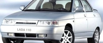
Car modifications 2115
VAZ-2115 . The very first car that was produced since 1997. It was equipped with a 1.5-liter carburetor engine producing 76 horsepower. The maximum speed was 165 km/h, and the acceleration time from 0 to 100 km/h was 13.2 seconds.
VAZ-21150 . The next modification, released in 1998, was equipped with a 1.5-liter carburetor engine producing 68 horsepower. was discontinued in 2000.
VAZ-2115-20 . A modification of the car released in 2000, equipped with a 1.5-liter VAZ-2111 injection engine with a power of 77.8 horsepower. The maximum speed was 170 km/h, and the acceleration time from 0 to 100 km/h was 14 seconds.
VAZ-2115-40 . A modification with a 1.6-liter injection engine, which has been produced since 2003. The car's maximum speed was 158 km/h, and the acceleration time to 100 km/h took 13.2 seconds.
VAZ-2115-91 . A car with a 1.3-liter Wankel rotary piston engine producing 135 horsepower. The maximum speed is 190 km/h, and the acceleration time to 100 km/h is 9 seconds.
VAZ-21154 . The latest modification of the car with a new VAZ-11183 engine with a volume of 1596 cm3 and a power of 81 horsepower. Produced since 2007. The maximum speed and acceleration time to 100 km/h are exactly the same as that of the VAZ-2115-40.
The starter does not turn over, what should I do?
In the life of owners of the VAZ-2114, and other cars close to this line (see above), sometimes such an unpleasant moment arises when you need to go somewhere, but it is not possible to start the power plant due to the fact that the starter does not turn the flywheel engine.
That is, when you turn the ignition key to the “start” position, nothing happens.
And if in the summer you can calmly look for the cause of the malfunction, then in the winter, in severe frost, you won’t spend much time searching for the malfunction. And in order to quickly fix a breakdown, you need to know where to look for it.
How to quickly start your car in cold weather, see below.
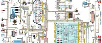
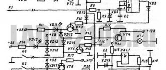
Electrical diagram of VAZ-2115-01
Years of production 2115: 1997—2012. This is a circuit with a regular button for rear fog lights (with locking), a fluorescent interior light, a connector for the clock and an 8-pin connector for the injector wiring.
1 — block headlights; 2 — fog lights; 3 — air temperature sensor; 4 - generator; 5 — electric motor of the engine cooling system fan; 6 — fan motor activation sensor; 7 — engine compartment lamp switch; 8 — block for connection to a single-wire type audio signal; 9 — sound signal; 10 — oil level sensor; 11 — front brake pad wear sensors; 12 — washer fluid level sensor; 13 — spark plugs; 14 — ignition distributor sensor; 15 - switch; 16 — carburetor solenoid valve control unit; 17 — carburetor solenoid valve; 18 — carburetor limit switch; 19 — speed sensor; 20 - starter; 21 - battery; 22 — relay for turning on fog lights; 23 — coolant level sensor; 24 — brake fluid level sensor; 25 — reverse light switch; 26 — coolant temperature indicator sensor; 27 — engine compartment lamp; 28 — windshield wiper gearmotor; 29 — oil pressure warning lamp sensor; 30 — block for connecting to the rear window washer electric motor; 31 — electric motor for windshield washer; 32 — ignition coil; 33 — instrument cluster; 34 — mounting block; 35 — brake light switch; 36 — blocks connected to the injection system wiring harness; 37 — ignition switch unloading relay; 38 — ignition switch; 39 — glove box lighting lamp; 40 — switch for the glove compartment lighting lamp; 41 — rear window heating switch; 42 — fog light switch; 43 — fog light switch; 44 — external lighting switch; 45 — alarm switch; 46 — steering column switch; 47 — instrument lighting regulator; 48 — hydraulic corrector scale illumination lamp; 49 — socket for a portable lamp; 50 — side direction indicators; 51 — switches in the front door pillars; 52 — lamp for individual interior lighting; 53 — electric heater fan; 54 — additional resistor of the electric heater fan; 55 — heater electric fan switch; 56 — backlight lamp for the electric heater fan switch; 57 — backlight lamp for heater control levers; 58 — display unit of the on-board control system; 59 — trip computer; 60 — switches in the rear door pillars; 61 — block for connection to the clock; 62 — electric fuel pump with fuel level sensor; 63 — ashtray lighting lamp; 64 — cigarette lighter; 65 — trunk lighting; 66 — trunk light switch; 67 — interior lamp; 68 — parking brake warning lamp switch; 69 — external rear lights; 70 — internal rear lights; 71 — plugs for connecting to the rear window heating element; 72 — license plate lights; 73 - additional brake signal.
See the complete diagram in one file below (click to enlarge):
There is a harness for the carburetor ignition system with a speed sensor; it is not connected to the injector. The 4th wire of the interior lamp is the ignition, so that when the ignition is turned on, the backlight goes out immediately. Jumper on Ш11 for wipers. On 2109 they are powered through a fuse on the motor (6-pin), here it is not used and therefore there are 5 wires going to the motor.
Circuit 2115 with “high” panel 21083 is similar to circuit 21099 (except for the rear harness).
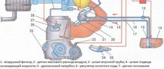
Operating principle
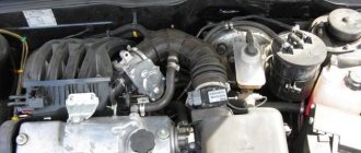
A fan is a device that allows you to increase the efficiency of a cooling radiator. The radiator takes heat from the engine and releases it into the air. This process is accelerated by blowing through the blades of an electric fan.
The coolant flows through a closed, sealed system. Its task is to remove excess heat from overheated engine parts. Hot antifreeze flows into the radiator, is cooled here and returns back. While in the radiator, the coolant passes through a system of thin tubes. The incoming air flow while the car is moving helps to quickly remove excess heat from the engine compartment.
But when the car is stuck in traffic or idling, the air flow stops cooling it. In this case, the cooling system may not cope with its task. An electric radiator fan is designed to create air flow artificially. The temperature for turning on the fan on a VAZ 2114 is 85 degrees Celsius.
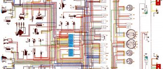
Scheme of VAZ-2115 Lux configuration
Luxury equipment is a model with headlight cleaners, heated seats, electric windows, central locking, trip computer and luminescent interior lighting.
- block headlights;
- gearmotors for headlight cleaners*;
- fog lights*;
- ambient temperature sensor;
- sound signals;
- engine compartment light switch;
- engine cooling fan electric motor;
- generator VAZ-2115;
- low oil level indicator sensor;
- washer fluid level sensor;
- front brake pad wear sensor;
- wire ends connected to the common windshield washer pump**;
- windshield washer pump;
- headlight washer pump*;
- wire ends for connecting to the rear window washer pump on VAZ-2113 and VAZ-2114 cars;
- low oil pressure indicator sensor;
- engine compartment lamp;
- wire lug for connecting to the engine management system wiring harness;
- windshield wiper gear motor;
- starter VAZ-2115;
- block connected to the wiring harness of the ignition system on carburetor cars;
- coolant temperature indicator sensor;
- reverse light switch;
- low brake fluid level indicator sensor;
- accumulator battery;
- low coolant level indicator sensor;
- relay for turning on fog lights;
- mounting block;
- brake light switch;
- plug socket for a portable lamp;
- hydrocorrector scale illumination lamp;
- parking brake indicator lamp switch;
- block for connecting a backlight lamp;
- switch for instrument lighting lamps;
- Understeering's shifter;
- hazard switch;
- front seat heating element relay;
- ignition switch;
- rear fog lamp circuit fuse;
- front seat heating elements circuit fuse;
- door lock circuit fuse;
- front ashtray illumination lamp;
- ignition relay;
- cigarette lighter VAZ-2115;
- glove box lighting lamp;
- glove compartment light switch;
- heater fan motor;
- additional heater motor resistor;
- heater fan switch;
- heater switch illumination lamp;
- heater lever illumination lamp;
- gear motors for electric windows of the front doors;
- right front door ESP switch (located in the right door);
- gear motors for locking front door locks;
- wires for connecting to the right front speaker;
- gear motors for locking rear doors;
- wires for connecting to the right rear speaker;
- door lock control unit;
- wires for connecting to radio equipment;
- headlight wiper switch*;
- rear window heating element switch;
- rear fog light relay;
- block for connection to the heating element of the right front seat;
- rear fog light switch;
- right front seat heating element switch;
- fog light switch*;
- switch for external lighting lamps;
- left front seat heating element switch;
- block for connection to the heating element of the left front seat;
- wires for connecting to the left front speaker;
- left front door power window switch (located in the left door);
- right front door power window switch (located in the left door);
- wires for connecting to the left rear speaker;
- side direction indicators;
- dome light switches on the front door pillars;
- dome light switches on the rear door pillars;
- lampshade VAZ 2115;
- individual interior lighting lamp;
- block for connecting to the wiring harness of the electric fuel pump;
- trunk light switch;
- instrument cluster;
- trunk light;
- on-board control system display unit;
- trip computer*;
- block for connecting the wiring harness of the engine management system;
- rear exterior lights;
- rear interior lights;
- pads for connecting to the rear window heating element;
- license plate lights;
- additional brake signal located on the spoiler.
Useful: Connection diagram for VAZ cooling fan
Numbering order of plugs in blocks:
A – headlight units and headlight cleaners; B – cigarette lighter; B – mounting block, instrument cluster, ignition switch, windshield wiper and other electrical components (for blocks with a different number of plugs, the numbering order is similar); G – relay for turning on the rear fog light; D – alarm switch; E – electric window motors and door lock motors; F – interior lamp.
In the instrument panel wiring harness, the second ends of the white wires are brought together into one point, which is connected to the instrument lighting switch (except for the white wire, from plug “4” of block “X2” of mounting block 28 to display block 83 of the on-board control system). The second ends of the black wires are also brought together to points connected to ground. The second ends of the yellow wires with a blue stripe are brought together to a point connected to plug “4” of the “X1” block of the mounting block. The second ends of the white wires with a red stripe are brought together to a point connected to plug “10” of the “X4” block of the mounting block. The second ends of the orange wires are brought together to a point connected to plug “3” of the “X4” block of the mounting block.
Explanations for the 8-pin injector block: white-red and blue - for the check light bulb, blue-red - ignition, gray - speed sensor, brown-red - tachometer, blue-white - driver's door switch (for the immobilizer), green- red - K-line (may not exist), green - fuel consumption. Next to it is a pink wire - to the fuel level sensor.
See the complete diagram in one file below (click to enlarge):
Video - connecting and checking VO
Overheating of the engine leads to serious problems: the pistons may jam, the cylinder block gasket may break, which leads to the need to overhaul the engine. To protect the power unit from overheating, it is important to maintain stable operation of the cooling fan. In this article we will discuss the operating principle of the device, its connection diagram, independent diagnostics and repair, as well as modernization of the control circuit. The instructions are fully suitable for VAZ 2115 and VAZ 2113 cars.
VAZ-2115 wiring harness diagrams
With a 9-pin square block for the injector, a non-locking button for turning on the automatic transmission, and a starter blocking relay (the injector turns off the starter if the engine is running).
Instrument panel harness
There is a relay for rear fog lights (attached next to the mounting block, the fuse dangles nearby), a button without locking. It works like this: if the low beam and/or front fog lights (if equipped) are on, press and release the button - the automatic transmissions turn on. They turn off when the button is pressed again or automatically when the headlights are turned off, so that the driver does not forget to turn them off.
Glove compartment lighting harness
There is a magnet on the lid; when it is far from the sensor with the reed switch, the glove compartment light turns on (the reed switch closes the contacts).
Front harness with fog lights
Rear harness VAZ-2115
License plate light harness
Wiper harness 2115
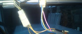
Additional harness – lock
Connects to the instrument panel, the connector is next to the hood handle. Pink - door lock, permanent plus, fuse hangs next to the hood release handle. White and black - on the door for electric windows, plus during ignition, switched on through a relay and fuse in the mounting block. Also in the photo is the wiring for the radio speakers.
Right door harness
Connects to an additional harness.
Left door harness
Connects to an additional harness.
Seat heating harness
The gray wire is connected to the connector where the additional harness is connected (to the gray wire if there is one), plus when igniting, the relay is attached next to the mounting block and the fuse is located next to the hood handle. The white wire is connected to the additional harness, button illumination.
Cooling fan diagnostics
If signals appear on the dashboard indicating that the permissible temperature level in the cooling system has been exceeded, this may indicate that the fan on the VAZ 2114 is not working. The main symptom of the malfunction is that the mechanism does not start even with a significant increase in temperature. It is urgent to turn off the engine to prevent its elements from overheating.
The engine should not be operated with a faulty electric cooling fan. This may damage the cylinder head.
If the cooling fan on a VAZ 2114 does not work, the following malfunctions may be the cause of the breakdown:
- The fan switch sensor on a VAZ 2114 has failed.
- Lack of contact at the sensor connector.
- The wiring has broken.
- Electric fan relay faulty.
- The fuse has blown.
- Damage to the device's electric motor drive.
Unplug the device. Connect it to the battery terminal. Maintaining polarity. If a direct connection to an energy source starts the electric motor, then the drive is working. There may be problems with the wiring, the fuse, or the temperature sensor.
Now it’s time to diagnose the fuse. You don't even have to open the plastic box to do this. If the relay malfunctions, the horn stops working at the same time as the fan. Therefore, if you notice the loss of the sound signal, it means that the fuse has definitely blown. You can find it in the engine compartment in a small plastic box. We release the cover, pressed by two latches, take out the burnt fuse with tweezers and replace it with a new one.
But diagnosing a relay is quite difficult. Especially for those who are exclusively “you” with auto electrics. To check functionality, the easiest way is to find a working relay and temporarily install it. If, after installing a new device, the fan begins to work properly, then it is time to replace the old one.
To diagnose the temperature sensor that supplies a signal to the radiator, you need to disconnect the connector from the sensor and start the ignition. The emergency mode will start, in which the electric fan will start blowing. If the fan starts late when the connector is disconnected, the sensor is most likely faulty. Replacing it will take no more than five minutes. You just need to unscrew two bolts using a Phillips screwdriver and install a new device in its place.
Even if a malfunction has occurred in the VAZ 2114 fan itself, this does not mean that it is time to change it. Sometimes you can simply replace a damaged bearing or brushes. But if the electric motor is faulty, it is much easier to purchase a new mechanism.