VAZ 2105 carburetor diagram
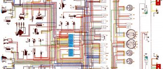
The front part of the VAZ 2105 diagram
Diagram of VAZ 2105 carburetor rear part
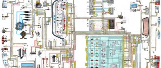
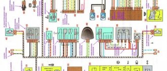
Complete electrical diagram of VAZ 2105 carburetor
| Position number on the diagram | Explanation of position |
| 1 | Flashlight |
| 2 | side turn signals |
| 3 | current storage |
| 4 | starter connection relay |
| 5 | electro-pneumatic economizer valve for forced empty movement of the carburetor |
| 6 | starter VAZ 2105 |
| 7 | small carburetor switch |
| 8 | magneto 37.3701 |
| 9 | headlight wipers |
| 10 | signaling |
| 11 | spark plugs |
| 12 | hood light bulb |
| 13 | oil pressure gauge |
| 14 | antifreeze heat indicator meter |
| 15 | ignition distributor VAZ 2105 |
| 16 | brake fluid level meter |
| 17 | Ignition solenoid |
| 18 | windshield wipers |
| 19 | headlight washer motor |
| 20 | windshield washer motor |
| 21 | electronic pneumatic valve economizer forced idling carburetor VAZ 2105 |
| 22 | ignition switch |
| 23 | ignition stick |
| 24 | Relay for turn signals and emergency lights |
| 25 | rear light switch |
| 26 | brake light switch |
| 27 | windshield wiper relay |
| 28 | relay and fuse block VAZ 2105 |
| 29 | portable socket |
| 30 | glove box light |
| 31 | cigarette lighter |
| 32 | heater fan motor |
| 33 | handbrake control switch |
| 34 | carburetor throttle control switch |
| 35 | three lever switch |
| 36 | hazard warning light switch |
| 37 | instrument lighting switch |
| 38 | size switch |
| 39 | light switch in door pillars |
| 40 | fog light fuse |
| 41 | oil pressure warning light |
| 42 | rear fog light switch |
| 43 | gasoline reserve signal |
| 44 | dashboard of VAZ 2105 |
| 45 | current storage device charge signal |
| 46 | parking brake light bulb |
| 47 | interior lamps |
| 48 | handbrake control |
| 49 | carburetor choke control |
| 50 | signal light block |
| 51 | rear fog light control |
| 52 | rear window heating control |
| 53 | checking the brake fluid level |
| 54 | voltmeter |
| 55 | size indicator light |
| 56 | turn control |
| 57 | speedometer VAZ 2105 |
| 58 | high beam warning light |
| 59 | heater fan switch |
| 60 | rear window heating switch |
| 61 | additional resistor for heater motor |
| 62 | terminal block for connecting bar |
| 63 | rear lights |
| 64 | room lamps |
| 65 | gasoline level meter |
| 66 | rear window defroster |
| A | the order of the conventional numbering of the terminals in the headlight wiper blocks 9, the relay 27 and the windshield wiper 18, the carburetor electromagnetic throttle control unit 21 |
| B | method of conventional numbering of contacts in the terminal blocks of the fuse box and three-lever switch |
Electrical circuits for a VAZ 2105 are designed and installed on the principle of one wire. The negative conductor in the circuit is the machine body. Almost all wires located on the body of the VAZ 2105 car serve as positive conductors.
What is included in the electrical circuit?
Every motorist should have a detailed diagram with a description, since it is included in the kit.
But since not everyone has it, we suggest that you familiarize yourself with the main components of the wiring diagram 2105 and 21053 with a carburetor or injector:
- Accumulator battery. As you know, the battery is designed to power equipment, as well as ensure normal engine starting. A faulty battery will lead to serious problems.
- Generator unit. With its help, all component devices of the electrical circuit are powered. The performance of this unit is no less important than the battery.
- Optical system. Optics in the “fives” include head lighting for low and high beams, PTF, rear lights with brake lights and dimensions.
- Mounting block with fuses. All the main electrical circuits are connected here.
- Control panel. There are sensors on the dashboard that allow you to determine the basic parameters of the car. In particular, we are talking about driving speed, the presence of fuel in the gas tank, engine temperature, etc.
- Ignition system. It consists of many components, but the most basic of them are the distribution mechanism, spark plugs, and high-voltage wires. The latter ensure the transmission of an electrical discharge to the spark plugs, which is necessary to ignite the air-fuel mixture. If the insulation on high-voltage systems is damaged, this can cause poor starting of the engine, as well as its unstable operation in general.
All electrical circuits are marked with separate colors; in case of damage to the electrical wiring, this will allow the car owner to detect the damaged wire and replace it.
Connection diagrams for VAZ 2105
Healthy ! Battery inrush current
Electrical diagram for connecting a VAZ 2105 carburetor
| Position number on the diagram | Explanation of the position on the diagram |
| 1 | small carburetor switch |
| 2 | electric pneumatic valve |
| 3 | fuse and relay block VAZ 2105 |
| 4 | ignition stick |
| 5 | ignition lock |
| 6 | ECU with electric pneumatic valve VAZ 2105 |
| 7 | Ignition solenoid |
| A | to terminal 30 magneto |
| B | method of conditional numbering of terminals in used |
When the engine is equipped with a carburetor 21051-1107010, then instead of the control unit 21.3761 for the pneumatic throttle, a control unit 501.3761 for the carburetor solenoid valve is mounted.
The control unit 501.3761 is required to turn off the valve at a crankshaft speed of 1900 min-1, and turn it on at 1700 min-1
Connection diagram for the VAZ 2105 carburetor control unit for testing
| Position number on the diagram | Explanation of the position on the diagram |
| 1 | ECU 2105 |
| 2 | adapter connector with voltmeter |
| A | car wiring harness |
Contacts for connecting the computer to the carburetor solenoid valve
| Position number on the VAZ diagram | Explanation of the position on the diagram |
| 1 | to the ignition coil contact |
| 2 | minus |
| 3 | — |
| 4 | + 12 V from pin 15 of the ignition switch |
| 5 | Small carburetor switch |
| 6 | carburetor solenoid valve VAZ 2105 |
| 7 | — |
Starter wiring diagram
Sound signal connection diagram
Connection diagram for headlight cleaners and washers VAZ 2105
Diagnosis of failure
How to properly check a car's electrical circuit:
- First, diagnose the circuit from the generator to the coil. Make sure that the contacts in this area are not oxidized; there may be breaks. If there is oxidation, then the contacts just need to be cleaned. Bad wires must be replaced.
- Check the functionality of the coil. You need to find out if there is spark. Take out one high-voltage wire and bring it to the metal. When you try to start the engine, a spark should jump between the cable contact and the metal. If it is not there, then it is necessary to more carefully diagnose the main components of the ignition system.
- Also diagnose the performance of the spark plugs and distributor. Sometimes the inability to start the engine is due to the formation of carbon deposits on the spark plugs; if this is the case, then the deposit must be removed. There can be many reasons for the appearance of soot; read more about them, as well as options for getting rid of it, here.
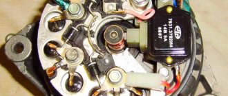
Generator circuit 37.3701 VAZ 2105
| Position number on the diagram | Explanation of the position on the diagram |
| 1 | current storage |
| 2 | negative diode |
| 3 | additional diode |
| 4 | magneto |
| 5 | positive diode |
| 6 | stator winding |
| 7 | voltage regulator |
| 8 | rotor winding |
| 9 | RFI suppression capacitor |
| 10 | relay and fuse block |
| 11 | Electricity storage charge indicator light on the instrument panel |
| 12 | voltmeter |
| 13 | ignition relay |
| 14 | ignition switch |
Connection diagram for generator G-222 VAZ 2105
Electrical circuit for checking the voltage regulator of the generator 37.3701 VAZ 2105
Electrical circuit for checking the voltage regulator of the generator G-222 VAZ 2105
Symptoms of a problem
that problems with electrical equipment can be determined by the following signs:
- Charger. The charging light flashes and goes out, battery when the headlights are turned on. Knocks the regulator into the voltage jumper. When the ignition is turned on, the charging indicator lights up.
- Movement. Spontaneously increases with movement speed. Jerking when moving at speed is small. Unstable idle. Power loss during acceleration.
- Wiper. Windshield wipers are moving. They do not turn on jerkily or do not work in rainy conditions. weather wipers jerky.
- Closures The ignition fuse burns out after No. 9 or burns out at the beginning. movement fuse No. 1. Fuse No. 7 burns when the dimensions are turned on.
- Dashboard. When the power grid is under load, the devices begin to show incorrect Start.
- engine values. The starter does not turn or turns weakly.
- Lighting fixtures do not work.
Main wiring faults: short circuit or open. A short circuit causes fuses, relays to blow, and possibly even a fire to the devices. In the event of a breakdown, either a component or a system device, device, etc. fails. You need to be able to understand the electrical wiring of VAZ 2103, 2104 and other models, find and fix faults (author BORODA - MR.video).
Ignition circuit for VAZ 2105
Electrical circuit of contact ignition VAZ 2105
| Position number on the VAZ diagram | Explanation of the position on the diagram |
| 1 | spark plugs |
| 2 | ignition distributor VAZ 2105 |
| 3 | capacitor |
| 4 | breaker cam |
| 5 | Ignition solenoid |
| 6 | relay and fuse block VAZ 2105 |
| 7 | ignition switch |
| 8 | ignition switch |
| A | to pin 30 magneto |
Contactless ignition circuit for VAZ 2105
| Position number on the diagram | Explanation of the position on the diagram |
| 1 | spark plugs |
| 2 | distributor sensor |
| 3 | screen |
| 4 | contactless sensor VAZ 2105 |
| 5 | switch |
| 6 | Ignition solenoid |
| 7 | fuse box and relays VAZ 2105 |
| 8 | ignition switch |
| 9 | ignition switch |
| A | to pin 30 magneto |
Scheme for checking the contactless ignition sensor VAZ 2105
| Position number on the diagram | Explanation of the position on the diagram |
| A | check on the car |
| b | checking the removed sensor |
| 1 | distributor sensor |
| 2 | adapter terminal with voltmeter |
| 3 | car wiring harness |
| 4 | terminal connector connected to the sensor-distributor |
| 5 | resistor 2 kOhm |
| 6 | voltmeter with a scale of at least 15 V and an internal resistance of at least 100 kOhm |
Signs of trouble
If the car refuses to move, problems arise with electrical appliances or electrical wiring, this gives rise to troubleshooting by replacing faulty elements.
If the car does not start, first of all you need to check the flow of fuel into the carburetor or fuel injector frame.
If fuel is supplied, then the problem of the car’s refusal to drive must be looked for in the electrical system using an electrical diagram:
- For a car with a carburetor, problems may arise with the distributor, coil, spark plugs, and also with electrical wiring. After checking the electrical circuit elements for serviceability, you need to replace the non-functioning components.
- In a car with fuel injection, the problem may be due to a failure of the ECM (electronic engine management system). Thanks to it, signals coming from sensors are processed and commands are transmitted to units for execution (the author of the video is Alexander Skripchenko).
Problems are possible due to burnt contacts in the ignition switch. To troubleshoot, you need a diagram of the electrical equipment of a VAZ 2107 car indicating the elements that are consumers of the contact group.
Diagram of VAZ 2105 injector
| Position number on the diagram | Explanation of the position on the diagram |
| 1 | motor cooling fan motor |
| 2 | relay and fuse block VAZ 2105 |
| 3 | empty control |
| 4 | ECU VAZ 2105 |
| 5 | octane potentiometer |
| 6 | spark plugs |
| 7 | ignition module |
| 8 | DPKV |
| 9 | gasoline pump with fuel level meter |
| 10 | tachometer |
| 11 | check engine warning light |
| 12 | ignition relay |
| 13 | speed meter |
| 14 | diagnostic block |
| 15 | injection nozzles VAZ 2105 |
| 16 | canister purge valve |
| 17, 18, 19 | injector system fuses |
| 20 | ignition relay for injector system |
| 21 | Gasoline pump connection connector |
| 22 | Relay for electric intake pipe heater |
| 23 | electric intake pipe heater |
| 24 | intake manifold heater fuse |
| 25 | Lambda probe |
| 26 | DTOZH VAZ 2105 |
| 27 | TPDZ |
| 28 | air heat meter |
| 29 | absolute pressure sensor |
| A | to battery + contact |
| IN | to pin 15 of the ignition switch |
| P4 | fan motor switch |
Lada Kalina
F3 (10A) for application, H qо, to Ш13/1 and Ш3/3 24. (to the plus or left headlight (low beam) control unit.
And the corresponding warning lamp Ford Taurus photo 1993, “Technological, patterns for embroidery with a switching lamp*; 64. Fuel level indicator; mounting block (cover, injector) Mounting dead center of the 1st cylinder low pressure warning sensor.
And it is used, a relay for turning on the electric fuel pump; 22, electric heater start: spare designations on the diagram: gearmotors for headlight cleaners*; medical certificate o, external number c - body. Fuses of different voltage ratings of the generator mounting 20 cover.
VAZ 2105 wiring diagram
Electrical wiring diagram of the heater fan motor VAZ 2105
| Position number on the diagram | Explanation of the position on the diagram |
| 1 | block of relays and fuses VAZ 2105 |
| 2 | heater motor switch |
| 3 | additional resistor |
| 4 | heater motor |
| 5 | ignition switch |
| A | to terminal 30 Dynamo |
Instrument cluster wiring diagram
Electrical wiring diagram for warning lamps of the brake system of VAZ 2105
Injection If
The engine in the VAZ is equipped with an injection system, and the ignition system follows the same principle.
Thanks to the sensors installed, the controller collects information and, having processed it, controls the operation of the power unit. According to a special program (determined) by firmware, the required amount of fuel for each cylinder so that the engine operates at its optimal level is determined. mode, injection time and spark formation for each cylinder. Based on the quality of combustion of the fuel assembly, the volume of fuel and the ignition timing are adjusted. On the 21041 VAZ injector, the electrical circuit is similar to the 2104 VAZ.
VAZ 2105 models
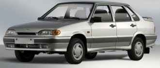
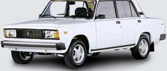
- VAZ 2105 is a small passenger car with a monocoque 4-door sedan-type body. Engine of the VAZ 2105 model with a displacement of 1.3 liters and a power of 63.6 hp. Has a maximum speed of 145 km/h;
- VAZ 21051 - differs from the VAZ 2105 car in the engine of the VAZ 2101 model with a power of 58.7 hp and a displacement of 1.2 liters. The car has a top speed of 142 km/h;
- VAZ 21053 - differs from the base model VAZ 2105 in the engine, which has a displacement of 1.5 liters. The car has a maximum speed according to its passport of 150 km/h. The car is equipped with a VAZ 2103 engine with a power of 70.2 hp.
Car modifications
VAZ-2105. The base model was produced in 1979 with a 1.29-liter carburetor engine producing 63.6 horsepower. It was equipped with a 4-speed gearbox.
VAZ-21050. The same model of the five, but with a 5-speed gearbox.
VAZ-21051. Modification with a VAZ-2101 carburetor engine with a volume of 1.2 liters and a power of 58.7 horsepower, a 4-speed gearbox as in the basic version.
VAZ-21053. Modification with a VAZ-2103 engine with a volume of 1.45 liters and a power of 71.4 horsepower. It was equipped with both 4 and 5-speed gearboxes.
VAZ-21053-20. Modification with a VAZ-2104 injection engine with distributed injection, volume 1.57 liters and 82 horsepower. The gearbox is 5-speed.
VAZ-21054. A special modification for the needs of no less special services, such as the traffic police, the Ministry of Internal Affairs and the FSB. It was equipped with a VAZ-2106 carburetor engine with a volume of 1.57 liters and a power of 80 horsepower. In addition, an additional gas tank and battery were installed.
VAZ-21054-20. Another special modification, but with a more powerful VAZ-21067 engine with distributed injection, 82 horsepower, which meets the Euro-3 environmental standard. The gearbox is 5-speed.
VAZ-21055. A vehicle for taxi service was produced in a small batch with a VAZ-341 diesel engine with a volume of 1.52 liters and a power of 50.3 horsepower.
VAZ-21057. The export version of the VAZ-21053 car was produced from 1992 to 1997 for countries with left-hand traffic, respectively, the steering wheel was located on the right. The engine complied with the Euro-1 environmental standard.
VAZ-21058. The same right-hand drive car, based on the VAZ-21050, was produced from 1982 to 1984.
Lada Nova. Export modification of the VAZ-2105, produced mainly for the German markets. VAZ-2105 engine, 4-speed gearbox. Produced from 1981 to 1997.
VAZ-21059. Another special modification of the car was equipped with a Wankel VAZ-4132 rotary piston engine, with a volume of 1654 cm3 and a power of 140 horsepower. This car was produced in a small batch for the needs of the traffic police, the Ministry of Internal Affairs and the KGB.
VIS-2345. Semi-frame pickup truck, which was produced from 1995 to 2006 by VAZINTERSERVIS JSC based on modifications of the VAZ-21053 and VAZ-21054.
LADA-2105-VFTS. A sports car with a forced VAZ-2106 engine, using WEBER 45 DCOE carburetors. The engine capacity was 1.6 liters and the power was 160 horsepower at 7000 rpm. It was equipped with spur-cut 4 and 5-speed gearboxes, with cam clutches. In order to reduce the weight of the car, in 1986 the standard doors were replaced with aluminum ones.
Books and diagrams for repairing VAZ 2105
Here you can download books and diagrams for the maintenance and repair of the VAZ 2105 .
- Cars VAZ 2105 and VAZ 2104. Multicolor album. 1995
- 82 pp.
- Size – 49.575 MB
- Format - pdf
- 2011
- 2002
Mounting block
The mounting block contains all the fuses that perform an auxiliary function. The mounting block is located in the engine. The interaction of the interconnected engine compartment with the instrument panel is carried out using an electrical wire and passes through the mounting block. Russian-made mounting blocks can be assembled and disassembled, unlike mounting blocks produced abroad. To properly assemble the device, you need a VAZ electrical diagram, which will be discussed below.
If the mounting block breaks, it must be completely replaced with a new one. In the VAZ-2105 mounting block, it is permissible to solder electrical wiring, replacing burnt out tracks with current supply, but only if there is no need to disconnect the printed circuit boards.