During the operation of the car, problems may arise that can only be solved after studying the electrical circuits. The article presents detailed wiring diagrams for the Lada 4×4 SUV (VAZ 2121), which will help you not only repair the car, but will also be useful when installing additional electrical equipment, for example, a car alarm, DVR and other accessories..
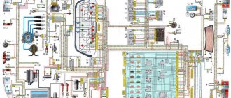
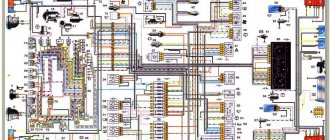
Electrical diagram of VAZ-21213
1 — headlights; 2 — side direction indicators; 3 — electric motor for windshield washer; 4 — headlight washer motor*; 5 - switch; 6 - battery; 7 - starter; 8 - generator; 9 — headlights; 10 — gearmotors for headlight cleaners*; 11 — sound signal; 12 — spark plugs; 13 — carburetor limit switch; 14 — carburetor solenoid valve; 15 — ignition coil; 16 — windshield wiper gearmotor; 17 — carburetor solenoid valve control unit; 18 — ignition distributor sensor; 19 — coolant temperature indicator sensor; 20-oil pressure warning lamp sensor; 21 — plug socket for a portable lamp**; 22 — brake fluid level warning lamp sensor; 23 — windshield wiper relay; 24 — relay for turning on the rear fog light***; 25 — relay for turning on the heated rear window; 26 — relay for turning on headlight cleaners and washer*; 27 — relay for turning on low beam headlights; 28 — relay for turning on the high beam headlights; 29 — ignition relay; 30 — starter activation relay; 31 — relay-breaker for alarm and direction indicators; 32 — heater electric motor; 33 — additional resistor of the heater electric motor; 34 — backlight lamps for heater control levers; 35 — external lighting switch; 36 — main fuse block; 37 — additional fuse block; 38 — reverse light switch; 39 — brake light switch; 40 — instrument lighting regulator; 41 — ignition switch; 42 — three-lever switch; 43 — alarm switch; 44 — tailgate glass cleaner and washer switch*; 45 — heater motor switch; 46 — switch for heating the rear door glass; 47 — rear fog light switch; 48 — lamp switches located in the door pillars; 49 — interior lamps; 50 - cigarette lighter; 51 — switch for the warning lamp for covering the carburetor air damper; 52 — control lamp for covering the carburetor air damper; 53 - switch for differential lock warning lamp; 54 — parking brake warning lamp switch; 55 — sensor for level indicator and fuel reserve; 56 — instrument cluster; 57 — tailgate glass washer motor; 58 — rear lights; 59 — block for connecting additional brake lights; 60 — blocks for connecting side marker indicators; 61 — pads for connecting to the heated glass element of the tailgate; 62 — license plate lights; 63 — gear motor for tailgate glass cleaner.
The order of conditional numbering of plugs in the blocks : a - windshield wipers, headlights and tailgate glass, windshield wiper relay breaker; b — ignition distributor sensor; c — relay-interrupter for alarm and direction indicators; g - switch; d — three-lever switch; e — alarm switch; g — relay for turning on the rear fog light; h — rear lights (numbering of terminals in order from top to bottom); and — instrument clusters.
In the instrument panel wiring harness, the second ends of the white wires are brought together to one point, which is connected to the instrument lighting control. The second ends of the black wires are also brought together to a point connected to ground. The second ends of the yellow wires with a blue stripe are brought together to a point connected to terminal “A” of the main fuse block. And the second ends of the orange wires are also brought together to a point connected to terminal “B” of the main fuse block.
* Installed on parts of manufactured cars; **not installed since 2000; *** installed since 2001. Previously, the rear fog light was switched on directly by switch 47, powered by fuse 3 of the additional fuse box.
Instrument panel tuning
Installation of the VAZ 2110 dashboard on Lada 4×4 (VAZ 2121, 2131)
Many owners of domestic cars strive to make some improvements to their design in order to give the car a more modern and, at the same time, more individual look. An excellent option in this case would be tuning the dashboard.
You can do it in two ways - replace the “native” panel with a Europanel or make changes to the backlight on the basic version.
In the first case, to replace you will need:
- unscrew the 3 screws securing the center console;
- remove the cover;
- unscrew the 5 screws located on the right side of the console and remove the screen;
- disconnect the ground terminal from the battery;
- remove the radio (if installed);
- disconnect the wiring harness going to the cigarette lighter and dismantle it;
- remove the handle from the levers using a narrow blade or screwdriver;
- remove the handle;
- disconnect the wires from the block;
- unscrew the mounting bolts;
- unscrew the bottom bracket fastening;
- unscrew the light guide screw, remove the light guide;
- unscrew the heating unit fasteners;
- remove the hydraulic corrector lamp (in order to unscrew it, you will need a 21 key);
- remove the sockets of all lamps;
- remove the decorative insert;
- unscrew all remaining fixing nuts;
- remove the dashboard.
After installing the europanel, assembly is carried out in the same order, but in reverse order (when connecting electronics, the diagram of the VAZ 2114 instrument panel is taken into account).
A more budget-friendly tuning option is to install LED instrument lighting on the panel. In order to make it, you will need to purchase a set of new light bulbs and sockets for them. Having removed the panel, the old cartridges are dismantled by unscrewing them counterclockwise, after which new ones are installed. After all the cartridges have been replaced, LEDs are installed in them.
After all the LEDs are installed, you should search for errors using the on-board computer. If they are found, you should check whether the electronic components are connected correctly (the pinout of the VAZ 2114 dashboard must exactly correspond to the actual connection diagram). If no errors are found, you can reinstall and reassemble the dashboard.
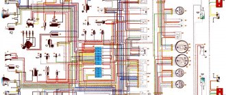
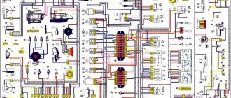
Electrical diagram of VAZ-2121
1 — headlights; 2 — side direction indicators; 3 — headlight washer motor*; 4 - voltage regulator; 5 — battery charge warning lamp relay; 6 - battery; 7 - starter; 8 - generator; 9 — headlights; 10 — gearmotors for headlight cleaners*; 11 — sound signals; 12-spark plugs; 13 — carburetor solenoid valve; 14 — ignition coil; 15 — windshield wiper gearmotor; 16 — coolant temperature indicator sensor; 17 — ignition distributor; 18 — windshield washer electric motor; 19 — oil pressure indicator sensor; 20 — oil pressure warning lamp sensor; 21 — brake fluid level warning lamp sensor; 22 — plug socket for a portable lamp; 23 — relay for turning on headlight cleaners and washer*; 24 — relay for turning on low beam headlights; 25 — relay for turning on the high beam headlights; 26 — windshield wiper relay; 27 — additional fuse block; 28 — main fuse block; 29 — additional resistor of the heater electric motor; 30 — reverse light switch; 31 — brake light switch; 32 — heater electric motor; 33 — relay-interrupter for alarm and direction indicators; 34 — parking brake warning lamp switch; 35 — alarm switch**; 36 — cigarette lighter; 37 — switch for cleaners and headlight washers*; 38 — heater motor switch; 39- external lighting switch; 40 — three-lever switch; 41 — ignition switch; 42 — instrument lighting switch; 43 — lamp switches located in the door pillars; 44 — interior lamps; 45 — oil pressure gauge with insufficient pressure warning lamp; 46 — fuel level indicator with reserve warning lamp; 47 — tachometer; 48 — parking brake warning lamp; 49 — battery charge indicator lamp; 50 — control lamp for the carburetor air damper; 51 — side light indicator lamp; 52 — turn signal indicator lamp; 53 — control lamp for high beam headlights; 54 — speedometer; 55 — carburetor air damper warning lamp switch; 56 — relay-interrupter for the parking brake warning lamp; 57 — coolant temperature indicator; 58 — brake fluid level warning lamp; 59 — differential lock warning lamp; 60 - switch for differential lock warning lamp; 61 — rear lights; 62 — license plate lights; 63-sensor for level indicator and fuel reserve.
The order of conditional numbering of plugs in the blocks : a - windshield and headlight wipers, windshield wiper relay breaker; b — relay-interrupter for alarm and direction indicators; c — three-lever switch; d — hazard warning switch.
* Installed on parts of manufactured cars; ** on cars produced in the 90s, due to the installation of breaker relays 33 without the fifth terminal, the brown wire connecting switch 35 to breaker relay 33 is missing.
Closest relative from the USSR
Niva 2131 is a 5-door and extended modification of the very famous and worthy 3-door Niva 2121. It is produced at the Volzhsky Automobile Plant and has been mass produced since March 1993.
The car belongs to the class of vehicles with increased cross-country ability. The range of installed power units is represented by 1 engine. Its volume is 1.7 liters with a power of 83 horsepower. This unit works in tandem with a manual transmission.
Equipping this station wagon with permanent all-wheel drive allowed it to set records for cross-country ability. Not surprising, because the 2131 is intended, first of all, to move across terrain inaccessible to conventional vehicles.
Engine control system VAZ-21214
Connection diagram of the VAZ-21214 engine management system with central fuel injection under US-83 toxicity standards with controller 21214-1411010 (EFI-4 type) on VAZ-21214 vehicles : 1 - “CHECK ENGINE” control lamp; 2 — instrument cluster (fragments); 3 — electric fans of the engine cooling system*; 4 — electric heater of the intake pipe; 5 — air temperature sensor; 6 — absolute pressure sensor; 7 — coolant temperature sensor; 8 — block connected to the throttle position sensor; 9 — central fuel injection unit; 10 — block connected to the idle speed regulator; 11 — block connected to the nozzle; 12 — diagnostic block; 13 - controller; 14 — knock sensor; 15 — speed sensor; 16 — oxygen concentration sensor; 17 - adsorber; 18 — battery; 19 - main relay; 20 — fuse block of the engine control system; 21 — relay for turning on the electric fuel pump; 22 — relay for turning on the electric fan*; 23 — relay for turning on the electric heater of the inlet pipe; 24 — electric heater protection fuse; 25 — starter activation relay; 26 — ignition relay; 27 — main car fuse box (fragment); 28 — spark plugs; 29 — tachometer; 30 — electric fuel pump with fuel level sensor; 31 — ignition module; 32 — crankshaft position sensor; 33 - courtesy light switch, located on the driver's door pillar; 34 — control unit of the automobile anti-theft system**; 35 — status indicator of the car anti-theft system**; A - wire going to plug “50” of the ignition switch; B - wire going to plug “15” of the ignition switch; B - wire going to terminal “30” of the generator; G - rear wiring harness wires connected to the fuel level indicator; D - rear wiring harness wire connected to switch 33.
The order of conditional numbering of plugs in blocks : a - controller; b — control unit of the automobile anti-theft system; c — indicator of the state of the automobile anti-theft system; g — speed sensor; d — central fuel injection unit; e — electric fuel pump and oxygen concentration sensor; g — ignition module; h - absolute pressure sensor.
Connection diagram of the VAZ-21214 engine management system with distributed fuel injection under Euro-2 toxicity standards with controller 2123-1411020-10 (type MP 7.0) on VAZ-21214 vehicles : 1 - control lamp of the engine management system; 2 — instrument cluster (fragments); 3 — electric fans of the engine cooling system; 4 — courtesy light switch, located on the driver’s door pillar; 5 — status indicator of the car anti-theft system; 6 — control unit of the automobile anti-theft system; 7-coolant temperature sensor; 8 — air flow sensor; 9 — throttle assembly; 10 — block connected to the throttle position sensor; 11 — block connected to the idle speed regulator; 12 - controller; 13 — oxygen concentration sensor; 14 — knock sensor; 15 — crankshaft position sensor; 16 — speed sensor; 17 - adsorber; 18 — battery; 19 - main relay; 20 — diagnostic block; 21 — fuse block of the engine control system; 22 — relay for turning on the electric fuel pump; 23 — relay for turning on electric fans; 24 — main car fuse box (fragment); 25 — block connected to the additional wiring harness*; 26 — ignition module; 27 - tachometer; 28 — electric fuel pump with fuel level sensor; 29 — nozzles; 30 — spark plugs; A - rear wiring harness wire connected to switch 4; B - wires connected to plug “1” of fuse block 24 (one wire goes to plug “15” of the ignition switch, and the other to plug “85” of the ignition relay); B - rear wiring harness wires connected to the fuel level indicator.
The order of conditional numbering of plugs in blocks : a - controller; b — control unit of the automobile anti-theft system; in - air flow sensor; g — speed sensor; d — indicator of the state of the automobile anti-theft system; e — electric fuel pump and oxygen concentration sensor; g - throttle pipe; h — ignition module.
Electrical connection diagram of the EURO-4 ME17.9.7 ECM for cars of the LADA 4x4 family with engine 21214
:
1 – controller; 2 – diagnostic block; 3 – mass air flow sensor; 4 – coolant temperature sensor; 5 – phase sensor; 6 – electric fuel pump module; 7 – pads for the instrument panel harness and rear harness; 8 – ignition coils; 9 – spark plugs; 10 – electronic accelerator pedal; 11 – throttle pipe with electric drive; 12 – electric fan of the engine cooling system, right; 13 – electric fan of the engine cooling system, left; 14 – knock sensor; 15 – pads for the ignition system harness and injector harness; 16 – nozzles; 17 – solenoid valve for purge of the adsorber; 18 – control oxygen sensor; 19 – diagnostic oxygen sensor; 20 – crankshaft position sensor; 21 – APS control unit; 22 – APS status indicator; 23 – ECM fuse block; 24 – fuse for the power supply circuit of the electric fuel pump; 25 – electric fuel pump relay; 26 – left engine cooling system electric fan relay; 27 – relay for the electric fan of the right engine cooling system; 28 – ignition relay; 29 – pads for the ignition system harness and instrument panel harness; 30 – instrument cluster; 31 – vehicle speed sensor; 32 – brake signal switch; 33 – clutch pedal position signal switch; 34 – main fuse block; 35 – additional relay; 36 – contacts of the instrument panel harness pads and the front harness; 37 – contacts of the instrument panel harness and rear harness pads
Download all schemes in high quality To download files you need to log in to the site
turbomotor412 posted a number of diagrams in his BZ:
Let us remind you that you will find detailed instructions for repairing the Lada 4×4 SUV in this section.
0 0 0 0 0 0
Share on social networks:
Replacement.
Pinout of the dashboard of a VAZ 2107 injector
To remove the DS, you need to place the car on a flat surface. After this, it is best to disconnect the battery terminals to avoid errors in the BC.
Disconnect the wire terminals; to do this, press the plastic lock on the block. After this, use a wrench to unscrew the sensor from its seat. If you cannot unscrew it immediately, it is not recommended to use excessive force. You need to treat the threaded connection with WD-40, wait a few minutes and continue dismantling.
Installation of a new DS is carried out in the reverse order. When purchasing a new part, you need to pay attention to the external condition: the contacts must be treated with a sufficient amount of varnish, as this protects them from moisture. After completing the work, it is necessary to reset the on-board computer errors in order to remove the CHECK ENGINE error.
Also interesting: Fuses Niva 21214 injector
As for its location, look for the DS in the engine compartment in close proximity to the exhaust manifold. To be honest, the place where it is installed cannot be called ideal. While the car is running, the manifold heats up. The sensor wires rub against it, which over time leads to malfunctions and short circuits.
Replacing the VAZ speed sensor: step-by-step instructions:
- Drive into the pit - it will be more convenient to work from below - and wait until the engine cools down.
- Turn off the vehicle's power by removing the cable from the negative terminal of the battery. Do not close the hood after this, this will provide you with lighting.
- Locate the speed sensor on the transmission. Clean it and everything near it with a rag to remove any dirt.
- By pressing the spring clip, disconnect the wire block from the sensor.
- Dismantle the sensor itself by unscrewing it counterclockwise - with your fingers or an open-end wrench to “22”.
- Carefully, so as not to break anything, install a new part in place of the removed part. Connect the wire block to it and the procedure for replacing the speed sensor can be considered complete.
How to properly connect a new DS? It is important here that the device rod fits correctly into the fixing sleeve, otherwise rotation will not be transmitted to the sensor. If the sensor fits into the socket the first time, then everything is in its place, and if something prevents it from moving, then the rod did not get into the bushing
Possibilities of the daily mileage reset button
The mileage reset button on the Niva Chevrolet and Niva Travel has a lot of useful functions:
- Setting the time.
- View the outside temperature and on-board voltage.
- Mileage reset.
- Starting the self-diagnosis system
Each possibility should be considered separately.
Setting the time
Turn the barrel switch fully clockwise to set the clock. Shifts will take place one hour at a time. To adjust the minutes, you need to turn the button counterclockwise. The time will be saved independently and will be reset only after the battery is disconnected or after the instrument panel on the Niva is rebooted.
View outside temperature
To display the outside temperature on the left display, you need to briefly press the button and release. Pressing the button again will display the on-board network voltage on the display, if provided for by the version of the panel.
Mileage reset
To reset the mileage on your Niva Travel, press the button and hold until “0.0” appears on the bottom line.
Self-diagnosis system
The instrument panel on the Niva Chevrolet is being diagnosed. To do this do the following:
- With the ignition off, press and hold the mileage reset button.
- Turn on the ignition.
- You can release the button, and the arrows on the dashboard will begin to move and all the lights will light up. This way the panel checks the functionality of all elements.
- Pressing the button again will display the software version.
- Another press will show engine error codes.
Despite the possibility of engine diagnostics, its readings are not always correct and therefore do not inspire confidence. For diagnostics, you should use appropriate software and devices.
Features of the modification
First of all, the changes affected the engine management system and control instruments. In particular:
- The wiring diagram for Niva 21213 received an additional wiring harness in the engine compartment for connecting a microcontroller and sensors;
- On the Niva model of recent years of production, a more advanced power unit with the VAZ-21214 index is installed. Instead of a carburetor, it has a fuel frame with injectors from GM. The price of a car with injection has increased because of this;
- The instrument panel has changed - the design is borrowed from the VAZ 2108 model.
Unification of the instrument panel: LADA NIVA with a panel from VAZ 2108
Ignition system
The VAZ 21213 engine uses a non-contact ignition system consisting of:
- ignition distributor sensor (marking 3810.3706). It is responsible for creating control pulses supplied to the electronic switch;
- switch (model marking – 3620.3734) in climatic version U2.1 (corresponds to GOST 15150);
- ignition coils (marking 27.3705).
Electronic switch for VAZ 21213
Dashboard
A modified instrument panel appeared on the car. In particular, instead of a voltmeter, the manufacturer installed a low battery discharge lamp (no. 12 in the diagram).
Connection diagram of warning lamps and devices VAZ 21213 1997 onwards.
Other breakdowns
If no blown fuses are identified, then you need to check the integrity of the wires and the reliability of the connections of the terminals and connectors. Problems often arise due to battery discharge.
Fan failure is caused by incorrect connection of the alarm system or breakdown of the starter.
Also, the fuel pump often refuses to turn on if it fails:
- control relay;
- controller;
- wiring supplying this unit.
In general, the electrical circuit contains more than 70 elements, the malfunction of any of them can negatively affect the operation of the car.
https://youtube.com/watch?v=TYFkDkxAyJc
Symptoms of a problem
The wheel bearing is the most vulnerable part and the easiest to diagnose. A number of signs are determined even without disassembling the car. You can feel them while driving.
Vibration in the front wheels. This does not require observation from the outside. Vibrations can be felt in the cabin as a slight shaking of the steering wheel. Sometimes the bearing wear is so severe that the entire interior can vibrate.
1. Knock. The wheel bearing of a Chevrolet Niva can manifest itself in the form of a knocking sound in the front part of the car. If when driving, the front part makes noise, then everything is diagnosed while driving.
2. Heating. When the bearings fail, the wheel begins to move to the sides. Because of this, the friction area increases and the axle heats up. If after a trip the central part is very hot, the Chevrolet Niva Niva front wheel bearing needs to be repaired or replaced.
Device combination (instrument panel), designation of warning lamps, indicators and displays
Type of instrument cluster from 2022 (including Urban)
Multifunctional display on the instrument panel (combination) (under No. 21 in the figure above)
Type of instrument cluster until 2022
| Option 1 (updated, including Urban) | Option 2 |
All vehicle control devices are combined into an instrument cluster. It includes: a speedometer with a trip meter, a coolant temperature indicator, a fuel level indicator, a tachometer, and warning lights.
ATTENTION! The fuel level indicator, due to the design features of the fuel tank and fuel level sensor, in some cases may display information with a deviation from the true value: when driving for a long time uphill or downhill, especially with a lateral tilt, parking with a lateral tilt (for example, on a curb) , refueling a car with the engine running. In the above cases, to restore the true value of the fuel level readings, it is necessary to place the car on a horizontal platform, turn off and turn on the ignition again.
Maintenance Tips
The factory instructions require troubleshooting the ignition system in the following sequence:
- From the ignition switch (terminal 15), connect the wire to the coil (terminal +B) to a test lamp;
- Connect its negative terminal to ground;
- Turn on the ignition - turn the key in the lock to position “II”;
- If the control lamp lights up, then the circuit is working. If not, look for damage to the wire;
- With the ignition on, pull out the central wire from the coil from the distributor;
- Bring its metal tip to the cylinder block so that a gap of 3-4 mm forms between them;
- Turn on the starter for a few seconds;
- If the spark jumps, the coil is working.
Tip: you can quickly check the switch in one way - take it from a working car. If the car starts with the new switch, then you need to buy a new one.
General appearance and varieties
At the moment, there are several options for the instrument panel on the Niva Chevrolet and Niva Treval.
| Picture number | Years of manufacture | Applicability | Catalog number |
| 1 | 2006-2007 | Chevrolet Niva | 21230-3801010-00 |
| 2 | 2006-2009 | Chevrolet Niva | 21150-3801010-00 |
| 3 | 2009-2018 | Chevrolet Niva | 21230-3801010-10 |
| 4 | 2018-2019 | Chevrolet Niva | 21230-3801010-15 |
| 5 | 2019-2020 | Chevrolet Niva | 21230-3801010-17 |
| 6 | 2020… | Lada Niva Travel | 21230-3801010-17 |
Despite the external differences, these shields differ only in appearance, lighting, software and functions of the built-in BC. Otherwise, the icons and designations of these panels are absolutely the same.
Torpedo tuning Chevrolet Niva
To tune the torpedo, you must first remove it. Don't forget to turn off the power beforehand. After which you can either cover the torpedo with leatherette, or paint it with a spray can or spray gun in any color you like. If you decide to cover the dashboard with fabric or leatherette, to do this you need to take measurements from the dashboard and make patterns from them so that it is convenient to cut the material and not confuse anything with the dimensions.
The interior design plays an important role. To enjoy the trip, the driver must feel comfortable behind the wheel. Thanks to a wide selection of components, you can make the interior of any car, including a Chevrolet Niva SUV, comfortable. Once the seats and upholstery are replaced, the dashboard can also be upgraded to suit the owner's requirements.
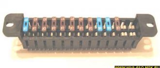
Circuit breakers
The block of protective devices in Niva is a board on which disposable fuses are installed, containing a fuse inside. Each of them protects one or more electrical circuits from overvoltage.
The unit is located in the cabin on the left side. Protective equipment is numbered. So, 1 is responsible for the work:
- windshield washer;
- stove fan;
- cleaners for all headlights;
- heating, wiper and washer for tailgate glass.
Video “Detailed overview of the Niva car wiring diagram”
In the video below you can see a step-by-step overview of the electrical circuit diagram for a domestic SUV (the author of the video is stups87).
Scheme of the first VAZ-2121
Years of manufacture: 1977-1993 content-27.foto.my.mail.r…ail/mr.chvans/79/s-94.jpg With tail lights and instruments from 2106
Scheme VAZ-21213 (Carburetor)
Years of manufacture: 1993-2009 content-25.foto.my.mail.r…ail/mr.chvans/79/s-97.jpg The diagram shows a relay for rear fog lights, used since 2000, before that they were turned on directly from the latching switch.
Since 2004, the car was renamed from NIVA to LADA 4x4
Since 2013, daytime running lights began to be used: a 2-filament lamp is installed at the side lights in the side light section. When the ignition is turned on, the power comes to the 21W thread (running lights mode), when the external lighting is turned on, the power switches to the 5W thread (side lights mode).
Schemes of the carburetor mixture control system are here www.drive2.ru/b/2168677/ There is a little information about the devices at the end of this article www.drive2.ru/b/1087776/
The structure of a car ignition switch
- Locking rod
- Frame
- Roller
- Contact disc
- Contact sleeve
- Block
- Protrusion of the contact part.
The lock mechanism is connected to many wires. They continue from the battery, connecting all the electrical devices of the car into a single chain. When you turn the ignition key, the electrical circuit is closed from the “-” terminal of the battery to the ignition coil. As a result, the current passes through the wires to the ignition switch, through its contacts it is directed to the induction coil, after which it returns back to the “+” terminal. As electricity passes through the coil, it generates high voltage, which it transmits to the spark plug. Therefore, the key closes the contacts of the ignition circuit, thereby starting the car engine.
Lada 4x4: On-board computer functions and setting the clock in the field.
Niva urban 2022 features part 3 Read more
Setting the Lada Granta watch More details
How to set the clock on the field Read more
On-board computer for the Niva "STAT 1m" More details
Car controls NIVA Lada 4*4 Buttons and levers More details
How to set the clock on a Chevrolet Niva and reset the daily mileage Read more
How to set the clock in the Niva 21213 / 21214 instructions for setting up the digital clock on the dashboard Read more
How to set the clock in the West Read more
Setting up your Chevrolet NIVA watch More details
Installation of on-board computer STATE 1M in Niva 21214m More details
AutoHelp #4 | Setting the clock on the Lada Priora dashboard Read more
LADA 4x4/ Replacement of low and high beam headlight bulbs on Niva. More details
On-board computer State X1M Functionality and installation of Lada Niva (Chevy Niva) More details
LADA Niva TRAVEL 2022. MULTIMEDIA (MMS) functions. E-Link, RADIO, AUDIO, VIDEO, NAVIGATOR, SETTINGS. More details
Additional disabling of MMS Lada Niva More details
Chevy Niva on-board computer Read more
On-board computer STATE Chevrolet Niva review of functions Read more
Source
Search form
Brake light switch. At this moment, the holes fall under vacuum; fuel from the float chamber through jet 26 rises up the tube, air is mixed from air jet 14, and the emulsion flows through the emulsion channel through the outlet holes under the throttle valve.
Below is a diagram of the VAZ You also have the option to opt-out of these cookies. The transition system of the second chamber ensures a smooth transition of engine operation at the moment the throttle valve of the second chamber begins to open.
When the generator is running, the battery is charged. Glove box light switch.
Only the main dosing system of the first chamber operates in throttling mode. These cookies will be stored in your browser only with your consent.
The starting device ensures the preparation of a rich combustible mixture when starting a cold engine. Scheme of operation of the starting device. Out of these cookies, the cookies that are categorized as necessary are stored on your browser as they are as essential for the working of basic functionalities of the website.
Limit switch Electromagnetic. VAZ is the same carburetor with a similar engine size. If it is a carburetor, then the electrical wiring will have certain differences. Air damper drive rod.
Circuit breakers
Through the main fuel jets 36 and 28, fuel enters the emulsion wells. Similar wires are insufficient wiring of the elk, which did not equip the circuit to realize its endless potential. Consciously: in Russia and the leading CIS countries it was not officially applied with a diesel snare. VAZ is the same carburetor with a similar engine size. When the throttle valve is opened sharply, the cam presses the lever 40 and, through a spring in the pusher, acts on the diaphragm 39, overcoming the resistance of the return spring.
Adjusting screw 1 allows you to adjust the amount of opening of the damper. A 30 A fuse protects the power supply circuit of the electric radiator fans, and three 15 A fuses protect the electric fuel pump, the control unit, the constant power input and the injection system main relay circuit, respectively, see Ignition coil. VAZ is the same carburetor with a similar engine size. Excitation of the Niva generator The simplest and most reliable circuit for supplying voltage to the excitation windings of the generator
Mounting blocks for Lada 4×4 2020
https://www.youtube.com/watch?v=SqqIBAU8osQ
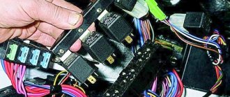
The turn signal relay (part number 8450082700, 9-pin), as well as the windshield wiper relay, are located under the trim in the driver’s feet, to the left of the fuse mounting block.
Read news about the new Niva
- Diagram and location of the fuse box Niva VAZ-21213 and 21214
- Diagram and location of the fuse box Niva VAZ-21213 and 21214
- Front lower suspension arms VAZ-2121 - Drawings, 3D Models, Projects, Cars and automotive industry (Car service)
- Timing marks on a Chevrolet Niva car
- Chassis, front suspension, device, Design, operation, description, device, car repair Niva VAZ 2121, engine, assembly, disassembly, transmission, gearbox
- Suspension lift in the field yourself | Niva Repair
- Niva 2121 suspension lift do-it-yourself drawings
- Tuning Niva 2121 with your own hands: body, interior, suspension