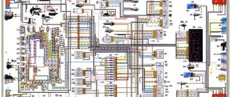
Electrical equipment of the VAZ 21214 car
Symbols on the diagram
1. Left front light. 2. Headlights. 3. Coolant temperature sensor. 4. Sound signal. 5. Throttle position sensor. 6. Mass air flow sensor. 7. Electromagnetic valve for adsorber purge. 8. Injectors. 9. Right front lamp. 10. Side direction indicators. 11. Rechargeable battery. 12. Electric heater motor. 13. Additional resistor for the heater motor. 14. Differential lock warning lamp switch.15. Windshield wiper relay. 16. Starter 21214. 17. Windshield wiper motor.18. Generator VAZ-21214. 19. Windshield washer motor.20. Ignition module. 21. Spark plugs.22. Controller. 23. Idle speed control. 24. APS status indicator. 25. Temperature indicator sensor.26. Oil pressure warning light sensor. 27. Socket for portable lamp(*). 28. Brake fluid level warning lamp switch. 29. Diagnostic block. 30. Relay for turning on the heated rear window. 31. Headlight high beam relay. 32. Relay for low beam headlights. 33. Electric fuel pump with fuel level sensor. 34. Starter activation relay. 35. Additional fuse block.36. Main fuse block. 37. Relay-breaker for direction indicators and hazard warning lights. 38. Reversing light switch. 39. Brake light switch. 40. Cigarette lighter VAZ-21214. 41. External lighting switch.42. Illumination lamps for heater control levers. 43. Rear fog light switch. 44. Rear window heating switch. 45. Heater motor switch. 46. Rear window wiper and washer switch. 47. Hazard switch. 48. Ignition switch. 49. Instrument lighting switch. 50. Windshield wiper switch. 51. Windshield washer switch. 52. Horn switch. 53. Turn signal switch. 54. Headlight switch. 55. Electric fuel pump relay. 56. Vehicle speed sensor. 57. Lamp switches located in the door pillars. 58. Interior lamps. 59. Rear window washer motor. 60. Instrument cluster. 61. Parking brake warning lamp switch. 62. Main relay. 63. Tail lights. 64. License plate lights. 65. Rear window wiper motor. 66. Rear window heating element. 67. Crankshaft position sensor. 68. Knock sensor. 69. VAZ oxygen sensor. 70. Electric fan relay. 71. Electric fans. 72. Injection system fuse block. 73. To the interior lamp. 74. To the courtesy light switch in the driver's door. 75. APS control unit.
Where are the fuse and relay boxes located?
The electrical equipment system, electrical wiring and arrangement of safety blocks on the Niva 21214 and the modern Chevrolet Niva VAZ 2131 are identical. The electrical circuit of these machines has a main mounting block installed under the lower edge of the instrument panel casing in the area of the driver's left foot. An additional one is located under the main block.
A little to the left and below there is another additional block, in which inserts are installed that are responsible for the operation of the components of the fuel injection system. In addition to the fuses, there is a separate relay for controlling the wiper operation parameters and a set of relays for the engine control system.
When installing an injection engine on a car with an old wiring diagram, the designers had to install additional switching boxes.
One of these blocks is located on the left side of the body near the main fuse box. Since the unit is installed in close proximity to the driver’s left foot, it is covered with a special protective plastic casing. The casing is fixed with two self-tapping screws for a Phillips screwdriver. The block itself contains a diagnostic connector and four fuses responsible for the operation of the engine and cooling system.
Block with cover removed
The relay responsible for turning on the engine starter can be installed separately in the engine compartment or next to the relay block. When installed under the hood, it is mounted on the compartment shield next to the brake fluid reservoir.
Replacing the block
In case of burnout or mechanical damage, it is necessary to repair the unit by replacing its components or the entire assembly.
To replace the main unit, follow these steps:
- Disconnect the battery from the on-board network.
- Remove the box cover and unscrew the two 8 mm nuts securing the block. Then you need to pull the box towards you and remove it from the fastening studs.
- Write down the markings and position of the wires on the old unit.
- Disconnect the cables from the plugs of the old unit and connect them in the same sequence on the new one.
- Check fuse ratings and wire installation.
- Secure the replaced block with nuts.
- Connect power to the on-board network and check the functionality of the circuits.
The photo shows some stages of dismantling the block.
Other fuse or relay blocks on the VAZ 21214 are replaced in the same way.
Video “Laying wiring in the sports version of the Niva”
You can learn more about this process from the video (author - Suprotec Racing channel).
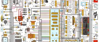
VAZ-21214. A high-quality color wiring diagram contains wiring indicating all components and elements - headlights, fans, switches and various sensors. The car's fuse and relay box is provided separately, with a detailed explanation of the purpose of each fuse link. All diagrams are taken from open sources and are provided for your viewing completely free of charge. By clicking on the picture below, the VAZ-21214 (NIVA) electrical equipment diagram will open in high resolution.
Designation and electrical diagram of the main and additional power supply
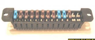
The designations and explanations of the fuses of the main and additional units are printed on the surfaces of the covers.
Diagram of the main and additional blocks
Description of the fuses in the upper main section of the VAZ 212214 Niva injector.
| Number on the diagram | Rated current, A | Purpose |
| PR01 | 16 | Heater fan motor, front glass fluid supply system, rear wiper motor |
| PR02 | 8 | Front wiper, direction indicators (with relay), switch block under the steering wheel, instrument cluster instruments and lamps, reverse indicator lamps |
| PR03 | 8 | High beam in the left headlight and high beam indicator lamp in the instrument cluster |
| PR04 | 8 | High beam for right headlight |
| PR05 | 8 | Low beam left |
| PR06 | 8 | Same as on the right |
| PR07 | 8 | Left side dimensions, registration plate illumination, dimensions indication on the instrument cluster |
| PR08 | 8 | Right dimensions and illumination of control devices |
| PR09 | 8 | Hazard warning relay circuit and activation button, rear defogger system |
| PR10 | 8 | Horn, interior lighting and brake lights (all three) |
Overview of the fuses of the small additional block located under the main one.
| Number on the diagram | Rated current, A | Purpose |
| PR11 and 12 | Positions are reserved | To store two 8 amp inserts |
| PR13 | 8 | Turning on the rear fog lamps |
| PR14 | 16 | Cigarette lighter |
| PR15 and 16 | Positions are reserved | For storing two inserts - 16 and 8 amps |
On Niva Urban 4x4 the fuse ratings have been slightly changed. The changed positions are listed below, the remaining chains and denominations remain the same.
| Number on the diagram | Rated current, A | Purpose |
| PR01 | 16 | Heater fan, start of heated rear window, drives for all windshield wipers and washer. Additionally (optional), this insert displays circuits for electric drives of windows and mirrors. |
| PR02 | 8 or 16 | Higher rating - heater fan and compressor (optional change - only for cars with air conditioning) |
| PR09 | 16 | Heated glass (there may be an additional option - heated mirrors) |
| PR10 | 16 | Horn, brake lights and interior lighting |
| PR11 | 8 | Alarm |
| PR12 | 8 | Daytime running light system |
| PR15 | 16 | Heater fan (not on all cars - only with air conditioning) |
The video by Vladimir Zhupikov shows a copy of Niva 21214 Urban with a heater fuse in position PR15.
Replacing fuses
If any electrical circuit in the vehicle fails, the condition of the fuse must be checked.
If it is necessary to replace parts, it should be taken into account that the VAZ 21214 fuses on the Niva injector belong to two different types:
- in the main block there are cylindrical inserts (inherited from the Zhiguli);
- and in the injection system blocks - modern, knife type.
Therefore, when you go on a trip, you need to take with you spare inserts of different types.
If, for example, a cigarette lighter fails on the road, you must:
- Turn off the ignition.
- Open the cover of the additional unit.
- Visually check the condition of the PR14 16 ampere fuse, which is responsible for the cigarette lighter circuit.
- Remove the burnt insert with your fingers and replace it with a spare one taken from the reserve socket PR15. It is prohibited to use homemade inserts, as they are not able to protect the circuit from overloads. The consequence of this may be overheating of the elements and fire.
- Check the functionality of the circuit. If the insert immediately burns out again, then the reason lies in damage to the wiring, which must be carefully checked.
The remaining fuses and relays on the VAZ 21214 are changed using a similar scheme.
Description
The main elements of the electrical circuit of the car in question are:
- pads for the engine control system (1) and the instrument panel (2);
- right interior lighting lamp (3);
- switch (at the right door) (4);
- fuel system (5);
- switch (at the left door) (6);
- left interior lamp (7);
- rear window wiper (8);
- tailgate wiper pad (9);
- number plate illumination (10);
- heated rear window (11);
- tailgate window washer (13);
- right rear light (14);
- brake signal (15);
- left rear light (16).
Engine control system fuses
Purpose and parameters of fuses in the block (from left to right):
- 1 — ensuring the start of the electric motor of the right fan (rated 30 A);
- 2 — similar fuse-link for the left fan;
- 3 - fan relay, as well as the injection system control unit, control of injection nozzles and ignition coil (rated 15 A);
- 4 - system for reducing gas toxicity - heating of lambda probes, fuel vapor trap valve and sensor for measuring the volume of air entering the engine (rated 15 A);
- 5 - diagnostic connector for monitoring the operating parameters of the injection system.
On some VAZ 21214 with an ABS system, a fuse block with 7 inserts is installed.
Block Niva Urban
Assignment of fuses (numbering starts from the door opening).
| Number | Rated current, A | Purpose |
| PR01 | 15 | Sensors on the engine, gasoline vapor trap, starter |
| PR02 | 15 | Fans, engine operation systems (control unit, ignition, injectors) |
| PR03 | 30 | Fan starting system |
| PR04 | 15 | Gasoline pump |
| PR05 | 5 | ABS unit |
| PR06 | 40 | Likewise |
| PR07 | 25 | Likewise |
Engine Control Relay Box
The engine control relay diagram is shown in the photo.
Engine control relay
The block contains the following relays (from left to right):
- 1 — ignition activation;
- 2 - main relay, which serves to start all engine systems;
- 3 — starting the right fan on the radiator;
- 4 — start of the left fan;
- 5 — ensuring the operation of the fuel pump;
- 6 - safety element of the fuel pump power supply circuit with a rating of 15 A.
Relay block diagram above the gas pedal
The diagram of the block with the relay, which is located slightly deep in the instrument panel and is responsible for lighting the car, is shown in the photo.
The purpose of the relay in the block (from left to right) is given in the table.
| Position | Purpose |
| 01 | Rear fog lamps |
| 02 | Heated glass on the rear door |
| 03 | Low beam |
| 04 | High beam |
Summarizing
The need to understand the wiring diagram may arise if there are malfunctions in the operation of the system and they need to be eliminated. Of course, complex malfunctions associated with the operation of the generator unit and other devices that are not simple in terms of design will be problematic to solve in a garage without certain knowledge. However, even simple knowledge of the electrical circuit and the ability to decipher the symbols can greatly help the car enthusiast during repairs. In addition, the need to understand wiring may also arise if you decide to upgrade your speakers or install a more advanced audio system.