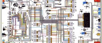
Electrical equipment of the VAZ 21214 car
Symbols on the diagram
1. Left front light. 2. Headlights. 3. Coolant temperature sensor. 4. Sound signal. 5. Throttle position sensor. 6. Mass air flow sensor. 7. Electromagnetic valve for adsorber purge. 8. Injectors. 9. Right front lamp. 10. Side direction indicators. 11. Rechargeable battery. 12. Electric heater motor. 13. Additional resistor for the heater motor. 14. Differential lock warning lamp switch.15. Windshield wiper relay. 16. Starter 21214. 17. Windshield wiper motor.18. Generator VAZ-21214. 19. Windshield washer motor.20. Ignition module. 21. Spark plugs.22. Controller. 23. Idle speed control. 24. APS status indicator. 25. Temperature indicator sensor.26. Oil pressure warning light sensor. 27. Socket for portable lamp(*). 28. Brake fluid level warning lamp switch. 29. Diagnostic block. 30. Relay for turning on the heated rear window. 31. Headlight high beam relay. 32. Relay for low beam headlights. 33. Electric fuel pump with fuel level sensor. 34. Starter activation relay. 35. Additional fuse block.36. Main fuse block. 37. Relay-breaker for direction indicators and hazard warning lights. 38. Reversing light switch. 39. Brake light switch. 40. Cigarette lighter VAZ-21214. 41. External lighting switch.42. Illumination lamps for heater control levers. 43. Rear fog light switch. 44. Rear window heating switch. 45. Heater motor switch. 46. Rear window wiper and washer switch. 47. Hazard switch. 48. Ignition switch. 49. Instrument lighting switch. 50. Windshield wiper switch. 51. Windshield washer switch. 52. Horn switch. 53. Turn signal switch. 54. Headlight switch. 55. Electric fuel pump relay. 56. Vehicle speed sensor. 57. Lamp switches located in the door pillars. 58. Interior lamps. 59. Rear window washer motor. 60. Instrument cluster. 61. Parking brake warning lamp switch. 62. Main relay. 63. Tail lights. 64. License plate lights. 65. Rear window wiper motor. 66. Rear window heating element. 67. Crankshaft position sensor. 68. Knock sensor. 69. VAZ oxygen sensor. 70. Electric fan relay. 71. Electric fans. 72. Injection system fuse block. 73. To the interior lamp. 74. To the courtesy light switch in the driver's door. 75. APS control unit.
Wiring diagram VAZ 21214 Niva
(2011), electronic gas pedal.
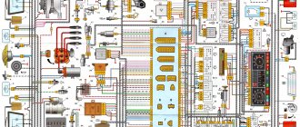
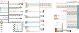
ELECTRICAL CONNECTION DIAGRAM FOR FRONT WIRING HARNESS 21214-3724010-44
1 – right headlight; 2 – starter relay; 3 – front harness block to the instrument panel harness block; 4 – air temperature sensor; 5 – coolant temperature sensor; 6 – oil pressure warning lamp sensor; 7 – sound signal; 8 – brake fluid level sensor; 9 – left headlight; 10 – pads for the front harness, the sidelight harness and the right side turn signal; 11 – pads for the front windshield wiper motor harness and electric motor; 12 – windshield wiper motor; 13 – blocks of the front harness and connecting starter wire; 14 – starter; 15 – rechargeable battery; 16 – generator; 17 – front harness block and connecting generator wire; 18 – right side turn signal; 19 – right side headlight; 20 – electric motor for washers; 21 – pads for the front harness, sidelight harness and left side turn signal; 22 – left sidelight; 23 – left side turn signal. A1, A2 – grounding points of the front wiring harness. A3 – grounding point of the hood ground wire. A4, A5 – grounding points of the connecting motor wire with the battery and housing.
ELECTRICAL CONNECTION DIAGRAM FOR IGNITION SYSTEM WIRING HARNESS 21214-3724026-44
1 – controller; 2 – diagnostic block; 3 – mass air flow sensor; 4 – coolant temperature sensor; 5 – phase sensor; 6 – electric fuel pump module; 7– block of the instrument panel wiring harness to the block of the rear wiring harness; 8 – ignition coils; 9 – spark plugs; 10 – electronic accelerator pedal; 11 – throttle pipe with electric drive; 12 – electric fan of the engine cooling system, right; 13 – electric fan of the engine cooling system, left; 14 – knock sensor; 15 – blocks of the wiring harness of the ignition system and the wiring harness of the injectors; 16 – nozzles; 17 – solenoid valve for purge of the adsorber; 18 – control oxygen sensor; 19 – diagnostic oxygen sensor; 20 – crankshaft position sensor; 21 – APS control unit; 22 – APS status indicator; 23 – ECM fuse block; 24 – fuse for the power supply circuit of the electric fuel pump; 25 – electric fuel pump relay; 26 – left engine cooling system electric fan relay; 27 – relay for the electric fan of the right engine cooling system; 28 – ignition relay; 29 – ignition system wiring harness block to the instrument panel wiring harness block.
ELECTRICAL CONNECTION DIAGRAM FOR INSTRUMENT PANEL WIRING HARNESS 21214-3724030-44
1 – additional relay; 2 – relay-interrupter of direction indicators; 3 – windshield wiper relay; 4 – ignition switch; 5 – alarm switch; 6 – rheostat; 7 – switch for headlights and direction indicators; 8 – windshield wiper and washer switch; 9 – main fuse block; 10 – additional fuse block; 11 – instrument cluster; 12 – external lighting switch; 13 – rear window wiper switch; 14 – rear window heating switch; 15 – rear fog light switch; 16 – heater motor switch; 17 – additional resistor of the heater electric motor; 18 – heater electric motor; 19 – relay for high beam headlights; 20 – low beam headlight relay; 21 – rear window heating relay; 22 – rear fog light relay; 23 – cigarette lighter; 24 – differential engagement sensor; 25 – brake signal switch; 26 – reverse lamp switch; 27 – handbrake warning lamp switch; 28 – illuminator; 29 – illuminator; 30 – instrument panel harness block to the front harness; 31 – block of the instrument panel harness to the radio; 32 – block of the instrument panel harness to the ignition system harness; 33 – instrument panel harness block to the rear harness; 34 – indicator lamp for turning on the differential;
35 – control lamp for heated rear window; 36 – clutch pedal position signal switch; 37 – speed sensor. A1, A2 – grounding points of the instrument panel wiring harness. A3 – grounding point of the heater motor.
REAR HARNESS ELECTRICAL CONNECTION DIAGRAM 21214-3724210-44
1 – rear wiring harness block to the instrument panel wiring harness block; 2 – rear wiring harness block to the ignition system wiring harness block; 3 – switch for the interior lighting in the driver's door pillar; 4 – switch for interior lighting in the passenger door pillar; 5 – left interior lamp; 6 – right interior lamp; 7 – electric fuel pump with fuel level indicator sensor; 8 – rear window heating element; 9 – additional brake signal; 10 – right lamp; 11 – left lamp; 12 – license plate light; 13 – license plate light; 14 – electric motor for rear window wiper; 15 – rear window washer electric motor. A1 – grounding point of the rear window heating ground wire. A2 – grounding point of the right lamp. A3 – grounding point of the left lamp. A4 – grounding point of the wiring harness of the license plate light housing. A5 - A8 - grounding points of the rear wiring harness assembly.
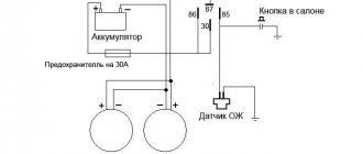
Connection via 5-pin relay
Now it's time to learn how to connect running lights via a five-pin relay. The scheme is the most universal, and was assembled to eliminate the disadvantages of previous options.
First, about connecting the relay for DRLs:
- 30 – to the positive terminals of LED modules;
- 85 – to the positive wire of the side lamp;
- 86 – on the car body;
- 87a – to “+” from the ignition switch;
- 87 – do not connect (isolate).
The circuit with a five-contact relay works as follows. When you turn the key, +12 V is supplied to the DRLs, thereby turning them on. If you turn on the side lights or headlights, the relay will open contact 87a and close inactive contact 87. As a result, the DRLs will go out and the side lights will turn on. The circuit fully complies with the requirements of GOST and traffic regulations and can work with side lights even based on LEDs.
However, the circuit still has one negative point - the DRLs will turn on immediately after turning the ignition switch. That is, if you turn the key in the ignition but do not start the car, the DRLs will light up.
Despite the existing drawback, the circuit is quite successful, but in order to correctly connect the DRL via a five-pin relay, you will need to supplement the circuit with a voltage stabilizer.
This switching option is interesting because the path of current flow through the running lights is independent. This allows you to install light sources of any type and power in headlights and DRLs.
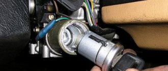
Removing and installing the starter
The starter on a Niva rarely has to be changed, but if you have a need for this, the instructions below will be very useful. First, it’s worth considering the necessary list of tools with which doing all this will be very simple and will not take much time.
- Key for 13
- Ratchet with small extension
- Head for 10
Detailed guide to replacing the starter on Niva VAZ 2121
First of all, open the hood of the car and disconnect all the power wires from the starter structure. To do this, you will need to unscrew the nuts that secure the terminals with a 10mm head. It is impossible to get there with a regular wrench, so a ratchet with a head and an extension would be an ideal option. We feel for the terminal nuts with our hands and, using the ratchet handle, unscrew them one by one.
To show everything clearly, look at the photo below; the key is inserted just under the Niva’s exhaust manifold:
And after that, you can freely disconnect the power wires, which are not attached to anything else:
Next, take a 13mm wrench, it’s more convenient to use a spanner, and unscrew the 2 bolts securing the starter housing to the engine. But there may be three of them; personally, in my example there were only 2.
And then you can shoot it to the right, as clearly shown in the photo below:
And turning it a little to the side, we take it out without any problems:
As you have seen for yourself, there is nothing complicated in this repair, the main thing is that you have all the necessary tools at hand and then any work on your Niva will be done quickly and without unnecessary nerves.
We install the VAZ 2121 starter in the reverse order of removal. If necessary, we replace it with a new part.
Daytime Running Lights
Daytime Running Lights
Post by Moonlight » Nov 20, 2010, 11:58 am
Re: Daytime running lights
Post by ALK » Nov 20, 2010, 12:28 pm
LED strip cut in epoxy+crank or resistance
z.y.y. I'm more concerned about the movement on the roundabout.. who is inferior? or if there are priority signs, then we follow the signs... in front of the circle there are signs “Give way” and “circular traffic”, then everyone on the circle has priority?
Who knows what's going on behind the fence of the zoo? ©
Re: Daytime running lights
Post by Moonlight » November 20, 2010, 12:51 pm
Re: Daytime running lights
Post by EVR » 20 Nov 2010, 14:06
Re: Daytime running lights
Post by Moonlight » 20 Nov 2010, 14:43
Re: Daytime running lights
Post by ryzhijlisik » 20 Nov 2010, 14:56
Re: Daytime running lights
Post by ryzhijlisik » 20 Nov 2010, 14:58
Re: Daytime running lights
Post by Himalaev » 20 Nov 2010, 15:07
Or remake the PTF into the DRL so that the traffic police do not incriminate traffic violations and the possibility of causing an accident involving several vehicles.
Re: Daytime running lights
Post by ryzhijlisik » 20 Nov 2010, 15:17
Re: Daytime running lights
Post by Himalaev » 20 Nov 2010, 15:26
Re: Daytime running lights
Post by ryzhijlisik » 20 Nov 2010, 16:07
Re: Daytime running lights
Post by Moonlight » November 20, 2010, 4:21 pm
Many people have a counter-question about the legality of using such DRLs when passing a technical inspection, since it is prohibited to use additional ones. lighting devices not provided for by the vehicle design. There is an answer to this from the traffic rules:
Installation in accordance with GOST According to GOST R 41.48-2004 “Uniform regulations regarding the certification of vehicles regarding the installation of lighting and light signaling devices,” installation of such devices on a vehicle is allowed. Clause 6.19 of this GOST allows for the optional installation of daytime running lights, provided that the placement complies with the standards (see figure)
and the functional electrical circuit will be proper. “If installed, the daytime running lights shall turn on automatically when the engine start/stop control is turned to the “on” position. It must be possible to activate and deactivate the automatic activation of daytime running lights without the help of a tool (without the participation of additional keys - editor's note). Daytime running lights must turn off automatically when the headlights are turned on, except when the headlights are turned on for a short period of time to signal road users.”
At night, they (LED daytime running lights) must turn off automatically, otherwise the glare effect will be even higher than from xenon.
Source
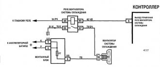
Connection via a 4-pin relay from a generator or oil sensor
The following two methods have a common basis and imply the operation of daytime running lights only after the engine is started. The circuit for switching on DRL from the generator is based on switching a four-contact relay and a reed switch.
The DRL relay contacts are connected as follows:
- 30 – to the positive terminals of LED modules;
- 85 – to the positive wire to the dimensions;
- 86 – to any reed switch output;
- 87 and the second terminal of the reed switch - to the “+” of the battery.
After checking the reliability of all contacts, proceed to setup. To do this, start the engine and, by moving the reed switch near the generator, achieve its activation and a stable glow of the DRL. Then the reed switch is hidden in a thermal tube and fixed in the found place using nylon ties.
At the moment of starting the engine, and then the generator, the contacts of the reed switch and relay close, supplying power to the LED running lights. In this case, the side lamps remain turned off, since the current through the relay coil is small to light them.
LED sidelights (headlights) with DRL function Niva 4*4 reviews
Average customer rating: (2) 3.00 out of 5 stars
no ratingREVIEW FOR THE PRODUCT LED SIDE HEADLIGHTS
Poor sealing, after 2 months, first one dimension fogged up, after 6 months. the other one will have to be disassembled and fixed, winter is ahead, and the LEDs may short out.
SIDE HEADLIGHTS
expensive, but they didn’t cheat on prepayment and it’s worth a lot
Please note that delivery is at the customer's expense and is not included in the initial cost of the order. Please wait until the company manager confirms your order to receive the total order amount. The period for generating and sending an order is 3-10 working days after receipt of payment in our accounts and depends on a number of factors:
— Orders that do not include a painting service , subject to product availability, are completed within 3-5 business days (estimated time frame). — Orders that include a painting service , subject to product availability, are completed within 7-12 business days (estimated time frame). — Individual orders are completed within 7-14 working days (approximate terms).
Scheme VAZ-2129, BA3-2130, VAZ-2131, VAZ-2329
Electrical diagrams of VAZ-2129, BA3-2130, VAZ-2131 and VAZ-2329 cars are provided. Previously, the version with the rear of the VAZ-21213 was mastered. Two modifications of the VAZ-2129 and 8AZ-2130 differed in the engine (1.7 or 1.8 liters), the location of the rear seat and the capacity of the gas tank. The three-door Kedr cars were replaced in 1996 by the five-door version of the VAZ-2131. With the same base extended by 500 mm. A pickup truck with a two-door, four-seater cab, the VAZ-2329, was produced in small quantities on special orders, but then, together with the VAZ-2131, it was transferred to main production. Unlike VIS trucks, the VAZ-2329 retained its monocoque body and spring rear suspension.
The collection of diagrams is intended for professional auto electricians and amateurs to help them perform small repairs on auto electronics with their own hands. At the end, see links to download useful literature on LADA.