As the requirements for the engine power supply system became more stringent, carburetors, as the most complex components on the way of gasoline and air to the cylinders, underwent serious modifications and went from simple fuel sprayers to serious multi-tasking pneumohydraulic devices.
In Russia, this path ended with the creation of Solex-type carburetors; nothing more advanced was produced in our country; the time has come for fuel injection systems.
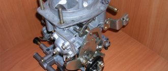
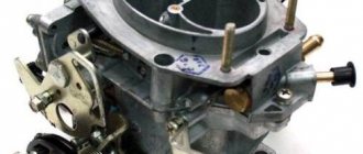
Carburetor
Carburetor appearance
1 – throttle valve zone heating unit; 2 – engine crankcase ventilation fitting; 3 – accelerator pump cover; 4 – electromagnetic shut-off valve; 5 – carburetor cover; 6 – air filter mounting pin; 7 – air damper control lever; 8 – starter cover; 9 – sector of the throttle valve drive lever;
10 – wire block of the EPHH screw sensor; 11 – adjusting screw for the “amount” of idle mixture; 12 – economizer cover; 13 – carburetor body; 14 – fuel supply fitting; 15 – fuel outlet fitting; 16 – adjusting screw for idle mixture composition (arrow); 17 – fitting for supplying vacuum to the vacuum ignition regulator.
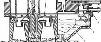
Diagram of the design and operation of the carburetor
I – first chamber; II – second chamber; 1 – accelerator pump drive lever; 2 – adjusting screw; 3 – starting device diaphragm; 4 – air channel of the starting device; 5 – electromagnetic shut-off valve; 6 – idle fuel jet; 7 – main air jet of the first chamber; 8 – idle air jet; 9 – air damper; 10 – sprayer of the main dosing system of the first chamber; 11 – accelerator pump nozzles; 12 – sprayer of the main dosing system of the second chamber; 13 – econostat sprayer; 14 – main air jet of the second chamber; 15 – air jet of the transition system of the second chamber; 16 – channel for balancing the float chamber; 17 – float chamber; 18 – needle valve; 19 – calibrated hole for fuel bypass into the tank; 20 – carburetor fuel filter; 21 – fuel supply fitting; 22 – power mode economizer diaphragm; 23 – fuel jet of the power mode economizer; 24 – ball valve of the power mode economizer; 25 – float; 26 – econostat fuel jet with tube; 27 – fuel nozzle of the transition system of the second chamber with a tube; 28 – emulsion tube of the second chamber; 29 – main fuel jet of the second chamber; 30 – outlet openings of the transition system of the second chamber; 31, 33 – throttle valves; 32 – slit of the transition system of the first chamber; 34 – outlet of the idle system; 35 – throttle valve zone heating unit; 36 – adjusting screw for the composition (the “quality” screw) of the idle mixture; 37 – engine crankcase ventilation fitting; 38 – fitting for supplying vacuum to the vacuum ignition regulator; 39 – main fuel jet of the first chamber; 40 – emulsion tube of the first chamber; 41 – ball valve of the accelerator pump; 42 – accelerator pump diaphragm.
A carburetor is used to prepare the fuel-air mixture of the required composition (depending on the engine mode). On engines -2108, -21081 and -21083, Solex-type carburetors are installed - emulsion type, two-chamber, with sequential opening of the throttle valves. The throttle valve drive is mechanical, cable. Carburetors have a balanced float chamber, a crankcase exhaust system, heating of the throttle valve area of the first chamber, a manual starting device, and an electromagnetic idle shut-off valve. The -21081 engine is equipped with a 21081-1107010 carburetor, the -2108 engine is equipped with a 2108-1107010 carburetor, and the -21083 engine is equipped with a 21083-1107010 carburetor. These carburetors are structurally similar and differ only in the flow sections of the jets.
Fuel is supplied to the carburetor through a strainer and needle valve. The latter maintains a given fuel level in the float chamber.
The float chamber is two-sectional (this design reduces the influence of fuel level fluctuations on engine operation when the vehicle turns and rolls). From the float chamber, fuel flows through the main fuel jets (first and second chambers) into the emulsion wells, where it is mixed with air passing through calibrated holes in the upper part of the emulsion tubes (main air jets). Through the nozzles, the fuel-air emulsion enters the small and large diffusers of the carburetor.
The idle system takes fuel from the emulsion well, after the main fuel jet of the first chamber. The fuel passes through the idle air jet (structurally combined with an electromagnetic idle shut-off valve), after which it is mixed with air from the channel from the idle air jet and from the expanding part of the diffuser (for stable operation when switching to idle mode). The resulting emulsion is fed under the throttle valve through a hole closed by a “quality” screw. The “quantity” screw (number of revolutions) adjusts the opening value of the throttle valve of the first chamber at idle.
When the throttle valve of the first chamber is partially opened (before the main metering system is turned on), the air-fuel mixture enters the chamber through a vertical slot located at the level of the throttle valve in the closed position; when the throttle valve of the second chamber is partially opened - through a hole located just above the throttle valve (second chamber) in the closed position.
The power mode economizer comes into operation when the throttle valves are opened significantly. Fuel is drawn from the float chamber through a ball valve. As long as the economizer diaphragm is held by vacuum in the intake manifold, the valve is closed. When the throttle valves open, the vacuum behind them drops and the valve begins to pass fuel, which flows through the economizer jet into the emulsion well, bypassing the main jet, enriching the mixture.
The econostat provides additional fuel supply directly from the float chamber (through the econostat nozzle and a tube system) into the second chamber. The econostat switches on at maximum power modes, further enriching the working mixture.
The accelerator pump is a diaphragm type, mechanically driven from the throttle valve axis of the first chamber through a profile cam. When the throttle valve opens, the cam acts on the lever, which in turn acts on the diaphragm. A portion of fuel is injected through nozzles into the carburetor chambers, enriching the combustible mixture during acceleration modes. The pump is equipped with two ball valves: a check valve is located in the channel connecting the float chamber with the cavity of the accelerator pump; it opens when it is filled with fuel (the gas pedal is released and the return spring moves the diaphragm back), and closes when fuel is pumped. The other valve is located in the sprayer; it opens under the pressure of the pumped fuel and closes under its own weight as soon as the fuel supply stops. This prevents fuel from leaking out of the channels and air leaks. The pump performance is not adjustable and depends only on the cam profile.
The starting device serves to enrich the air-fuel mixture when starting a cold engine. It is controlled from the driver’s seat with a “choke” handle via a rod. When the handle is pulled all the way, the three-arm air damper control lever, turning on an axis, acts with a profile groove on the air damper lever, closing it. In this case, with its outer profile (in the lower part) it acts on the throttle valve control lever of the first chamber, opening it slightly to the starting gap C (its value is adjusted by a screw on the lever). After the engine starts, the vacuum in the intake manifold increases; it is transferred to the cavity of the trigger device. Under the influence of vacuum, the diaphragm of the starting device, overcoming the resistance of the return spring, through the rod slightly opens the air damper to the starting gap B (its value is adjusted by a screw on the cover of the starting device). When the air damper control handle is recessed, gaps C and B are reduced; their value with a partially recessed handle depends on the profiles of the three-arm lever (its cutout and outer profile) and cannot be adjusted. If the choke control handle is pulled out, then when you press the gas pedal, only the throttle valve of the first chamber will open, while the throttle valve of the second chamber is blocked by the choke control lever. This prevents jerks and dips when driving with a cold engine (“on choke”).
Carburetor calibration data
| Options | 2108-1107010 | 21081-1107010 | 21083-1107010 | |||
| First camera | Second camera | First camera | Second camera | First camera | Second camera | |
| Mixing chamber diameter, mm | 32 | 32 | 32 | 32 | 32 | 32 |
| Diffuser diameter, mm | 21 | 23 | 21 | 23 | 21 | 23 |
| Main dosing system: | ||||||
| fuel jet marking | 97,5 | 97,5 | 95 | 97,5 | 95 | 97,5 |
| air jet marking | 165 | 125 | 165 | 135 | 155 | 125 |
| Emulsion tube type | 23 | ZC | 23 | ZC | 23 | ZC |
| Idle system and transition system | ||||||
| first chamber: fuel jet marking | 42* | — | 40* | — | 40* | — |
| air jet marking | 170 | — | 170 | — | 170 | — |
| Second chamber transition system: | ||||||
| fuel jet marking | — | 50 | — | 50 | — | 50 |
| air jet marking | — | 120 | — | 120 | — | 120 |
| Econostat: | ||||||
| conditional fuel jet flow rate | — | 60 | — | 70 | — | 70 |
| Power mode economizer: | ||||||
| fuel jet marking | 40 | — | 40 | — | 40 | — |
| spring compression force at a length of 9.5 mm, N | 1,5±10 % | — | 1,5±10 % | — | 1,5±10 % | — |
| Accelerator pump: | ||||||
| sprayer marking | 35 | 40 | 35 | 40 | 35 | 40 |
| fuel supply for 10 cycles (total for both chambers), cm3 | 11,5 | 11,5 | 11,5 | |||
| cam marking | 7 | — | 4 | — | 7 | — |
| Starting clearances: | ||||||
| air damper (gap B), mm | 3±0,2 | — | 2,7±0,2 | — | 2,5±0,2 | — |
| throttle valve (gap C), mm | 0,85 | — | 1,0 | — | 1,1 | — |
| Hole diameter for vacuum corrector, mm | 1,2 | — | 1,2 | — | 1,2 | — |
| Needle valve hole diameter, mm | 1,8 | 1,8 | 1,8 | |||
| Diameter of the fuel bypass hole into the tank, mm | 0,70 | 0,70 | 0,70 | |||
| Engine crankcase ventilation hole diameter, mm | 1,5 | — | 1,5 | — | 1,5 | — |
* Selected at the factory when setting up the carburetor.
What to do with jets
Now you can increase the diameters of the fuel jets. “Can” does not mean necessary, and if fuel economy is more important, then the jets are best left alone. Even after replacing them with jets of increased diameter, the car will not turn into a Maserati, but fuel consumption will definitely increase. If this doesn’t scare you, then change the standard jets to 107.5 and 115, and the air jets to 155 and 135 in the primary and secondary chambers, respectively. If you are not satisfied with the result, you can always install the standard jets in place.
Setting up the float chamber
This type of work allows you to adjust the optimal amount of gasoline in the float chamber. An incorrect level causes a decrease in power, uneven engine operation, and excessive fuel consumption.
- set of wrenches;
- thin probe (diameter 1 mm);
- pliers.
1. Remove the air filter and unscrew the carburetor cover.
2. Carefully remove the float chamber cover.
3. Check the condition and position of the floats. They should be parallel to the imprints of the side walls of the float bath on the gasket.
4. If they are displaced, we align them by bringing them together or spreading them apart.
5. Next, lay the lid horizontally with the floats up and use a feeler gauge to measure the distance from the bottom of the float to the gasket. It should be equal to 1 mm. If it is higher or lower, we continue further adjustment after installing the carburetor on the engine.
6. When fuel is pumped into the float chamber, its level should coincide with the red lines, as shown in the photo.
7. If the floats are set incorrectly, this level will be lower or higher. Simple adjustment is carried out by bending or bending the tongue of the floats, then closing the carburetor cover and pumping fuel.
For details on setting up the float chamber, see here
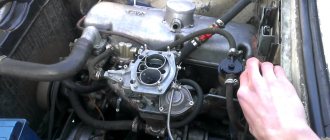
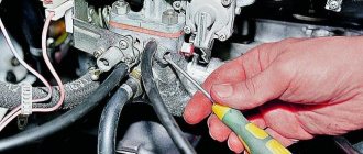
Restoring functionality
To troubleshoot a Solex carburetor, in most cases it is necessary to remove it from the engine. The operation is performed in the following order:
- the air filter housing is dismantled;
- the supply and return fuel lines, air tubes, wires, air and throttle valve control cables are uncoupled;
- The nuts securing the device are unscrewed.
When disassembling the device, all work should be done on a table or workbench covered with cloth or paper. The parts should be laid out in a certain order, which will allow nothing to be lost or mixed up during installation. Adjustment of the needle valve to set the optimal fuel level in the float chamber is carried out using a special template. The carburetor on the VAZ engine is installed in the reverse order, after which, if necessary, it is adjusted.
Setting up the launcher
- open-end wrench 7;
- open-end wrench 8;
- flat screwdriver;
- electronic tachometer or multimeter with its function.
1. Remove the air filter from the carburetor. Pull the “suction” towards you as far as it will go. Next, you will need an assistant to start the engine. At this time, you are watching the starter flap, which should open slightly after starting.
2. If this does not happen, it means that the starter is not adjusted.
3. We begin the adjustment. Warm up the engine, turn it off and connect the tachometer as follows.
4. Pull out the choke and start the engine. The suction valve must be completely closed.
5. Next, use a screwdriver to press on the edge of the damper, opening it 30 0 .
8. In this position, holding the bolt with a screwdriver, tighten the locknut.
The adjustment process can be seen in this video
Idle setting
- flat screwdriver;
- electronic tachometer.
1. Start the engine, warm it up to operating temperature, and then turn it off. We press the “choke” all the way, opening the flap of the starter device as much as possible. We connect the tachometer using the same principle.
2. Start the engine, turn on all the lights and the heater fan at full power.
4. If in this way it was not possible to achieve the required speed, unscrew the quality screw to the maximum number of revolutions. Next, turn the quantity screw, setting the motor to 900 rpm. After this, use the quality screw to reduce the speed to 800 rpm.
Details in the video
Design and operating principle
The carburetor supplies the engine with a fuel-air mixture in various modes. When starting from a “cold” state, the throttle valve is manually fully opened (the so-called “choke”), and the mixture entering the cylinders is completely enriched. After the engine warms up, the speed drops and the choke can be removed. Drivers remove it in different ways, but it is recommended to do it gradually.
The fuel in the carburetor is transferred to the float chambers from the diaphragm pump, and the needle valve controls the gasoline level. Through the chamber, the fuel passes into the channels of the body, where it enters the nozzles, and through them it goes into the first chamber. A fuel-air mixture is formed, which is supplied directly to the cylinders by the gas pedal. The second camera turns on only during sharp acceleration and operation at high speeds.
At idle, the IACV (idle speed solenoid valve) is turned on, while the engine runs stably and the car consumes much less fuel. However, on some devices it can be disabled; if it breaks down, the speed and consumption will only increase slightly, but the car will drive.
Upgrade options
Solex 21083 carburetors have gained wide recognition among many motorists not only due to their high performance, reliability and good characteristics, but also due to their upgrade capabilities. Among the main improvements that drivers most often make is boring out a larger diameter diffuser. But installation on power units with a cylinder capacity of more than 1.5 liters is undesirable, since stable operation of this carburetor model at high crankshaft speeds is impossible. In this case, adjusting the device will not help, since its design was developed for a specific group of motors. In addition, installation on other power units does not make sense due to the fact that for normal operation of the eight, a combustible mixture with a reduced oxygen content is sufficient, which will not be enough for other power units.
Signs of a carburetor malfunction
It is a well-known fact: the quality of fuel in our country leaves much to be desired. As a result, the carburetor may become clogged with oils, solid particles, etc.
In this case, one or more signs may be observed:
- significantly increased fuel consumption;
- the engine does not start “cold”;
- loss of dynamics;
- "triple" of the engine.
You can restore functionality yourself. If unsuccessful, you can remove it and take it to a mechanic, who, with an experienced eye, will immediately identify the errors and adjust it “by eye,” after which the car will at least start.
First, you can try adjusting the carburetor without removing it from the car.
Setup and adjustment
First of all, the engine warms up until the fan turns on. Next, adjust the speed by ear using the quantity screws. The operation should be smooth, with a sharp press on the gas pedal there should be no dips, and the speed should increase quickly and smoothly. The quality screw regulates the amount of exhaust gases. Ideally, no escaping gases should be visible from the exhaust pipe in the dry season (they will be, but not visible to the eye, if everything works correctly). Everything can also be done by looking at the tachometer readings. Unfortunately, many models of Soviet cars do not have it at all, so most often the adjustment will have to be done by ear.
His Majesty diffuser
If you pick up a diffuser, large or small, pay attention to the quality of the casting and show all this happiness to an engineer at least from Ford Europe, he will go crazy. A standard diffuser creates so many turbulences and parasitic flows in the intake tract that the efficiency of the carburetor is reduced by 20 percent. What kind of tuning can we talk about with such diffusers! Therefore, first of all, they need to be sanded, removing all the seams that create swirls.
Lada 2106. › Logbook › Solex carburetor 083 (Pekar) a lot of literature. And Photos of works.
The figure shows a VAZ Solex 21083 carburetor.
The design of the carburetor VAZ Solex 21083.
1. Carburetor heating unit 2. Throttle valve of the first chamber 3. Pipe for suction of crankcase gases 4. Accelerator pump drive lever 5. Accelerator pump drive cam 6. Accelerator pump diaphragm 7. Power mode economizer fuel nozzle 8. Pump housing 9. Economizer diaphragm power modes 10. Shut-off solenoid valve 11. Idle fuel jet 12. Carburetor cover 13. Main air jet of the first chamber 14. Air damper 15. Accelerator pump nozzles with fuel supply valve 16. Starter diaphragm 17. Starter adjustment screw 18. Adjusting screw for the amount of idle mixture 19. Locking lever of the second chamber 20. Pipe for supplying vacuum to the vacuum regulator of the ignition distributor 21. Adjusting screw for the quality of the idle mixture 22. Throttle valve control sector 23. Throttle valve drive lever 24. Adjusting screw for opening the throttle damper of the first chamber 25. Air damper control lever 26. Starter rod 27. Electrical wire of the limit switch of the forced idle economizer 28. Air damper lever 29. Main air jet of the second chamber 30. Emulsion tube 31. Sprayer of the main dosing system of the second chamber 32. Fuel supply pipe 33. Fuel drain pipe into the tank 34. Fuel filter 35. Needle valve 36. Second chamber throttle valve 37. Second chamber throttle lever 38. Second chamber main fuel jet 39. Second chamber throttle drive lever 40. Float
Engine 21083 technical specifications
Years of production - (1987 - 2004) Cylinder block material - cast iron Power system - carburetor Type - in-line Number of cylinders - 4 Valves per cylinder - 2 Piston stroke - 71mm Cylinder diameter - 82mm Compression ratio - 9.8 Engine displacement 21083 - 1499 cm cube Engine power VAZ 21083 – 73 hp. /5600 rpm Torque - 106 Nm / 3600 rpm Fuel - AI93 Fuel consumption - city 7.9 l. | track 7 l. | mixed 7.8 l/100 km Oil consumption - 50 g/1000 km Oil in the VAZ 21083 engine: 5W-30 5W-40 10W-40 15W40 How much oil is in the 21083 engine: 3.5 l. When replacing, pour 3.2 liters.
Engine life 21083: 1. According to the plant – 125 thousand km 2. In practice – up to 250 thousand km
TUNING Potential – 180+ hp. Without loss of resource - up to 90 hp.
The engine was installed on: VAZ 21083 VAZ 21093 VAZ 21099 VAZ 2110 VAZ 21111VAZ 2115
Carburetor Colex 21083 and its design
This type of carburetor produces a lean mixture, and if you want to improve the dynamics of your car, we recommend installing jets with a larger cross-section. Below is a diagram of the Solex 21083 carburetor.
Take a closer look at what basic elements our device consists of.
Breakdowns and their elimination - we repair the carburetor
Quite often, car owners encounter problems with the Solex carburetor. This happens while the car is moving, as well as when the engine is idling. It is quite easy to identify problems with the carburetor.
- When you try to start the car, it may stall, the tachometer speed on the instrument panel floats.
- When idling, exhaust may appear from the car pipe.
- While driving and changing gears, there may be dips in the gas pedal.
Solex 21083 carburetor design
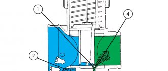
1 – driving lever, second drive chamber; 2 – screw adjusting the amount of mixture supplied for idle speed; 3 – sector for heating the carburetor; 4 – engine crankcase ventilation pipe; 5 – drive lever for the accelerator pump; 6 – solenoid shut-off valve; 7 – air damper lever; 8 – carburetor cover; 9 – special screw for fastening the liquid chamber; 10 – liquid chamber body; 11 – carburetor body; 12 – throttle valve lever of the second chamber; 13 – control lever block directly for the throttle valves; A - special marks for precise installation of the bimetallic spring of the starting device.
1 – axis for the float; 2 – needle valve; 3 – float; 4 – special gasket for the carburetor cover; 5 – starter cover; 6 – screw; 7 – trigger device diaphragm; 8 – special gasket; 9 – air damper lever; 10 – idle fuel jet; 11 – solenoid shut-off valve; 12 – pipe for supplying a combustible mixture; 13 – carburetor cover; 14 – fuel filter; 15 – housing assembly with drive levers of a semi-automatic starting device; 16 – screws for adjusting the air damper of the starting gap and slightly opening the first throttle chamber; 17 – special clamp for securing the bimetallic spring housing; 18 – liquid chamber; 19 – assembled housing with a bimetallic spring; 20 – bimetallic spring screen.
Solex 21083 carburetor diagram
1 – screw adjusting the amount of feed mixture for idle speed; 2 – electric wire of the limit switch economizer for forced idling; 3 – carburetor heating unit; 4 – diaphragm for the accelerator pump; 5 – accelerator pump cover; 6 – drive lever of the accelerator pump; 7 – accelerator pump drive cam; 8 – economizer cover for power modes; 9 – diaphragm for economizer of power modes; 10 – fuel jet for power mode economizer; 11 – power mode economizer valve; 12 – nozzles with a fuel mixture supply valve for the accelerator pump; 13 – sprayers of the main dosing systems; 14 – air main jets with emulsion tubes; 15 – fuel main jets; 16 – carburetor body; 17 – adjusting screw for the throttle valve; 18 – stopper for the adjusting screw; 19 – stopper cap; 20 – throttle valve of the second chamber; 21 – throttle valve axis of the second chamber; 22 – throttle valve rod for opening the first chamber; 23 – block with throttle valve control lever; 24 – return spring of the throttle valve of the first chamber; 25 – driven lever, drive of the throttle valve of the second chamber; 26 – driving lever, driving the throttle valve of the second chamber; 27 – spring of the throttle valve drive levers of the second chamber; 28 – throttle valve of the first chamber; 29 – return spring of the throttle valve of the second chamber; 30 – plug for the screw adjusting (composition) the quality of the idle mixture; 31 – axis of the throttle valve of the first chamber; 32 – screw adjusting the quality of the supplied idle mixture
What is a Solex 21083 carburetor?
Solex 21083 is one of the most popular domestic carburetors. It is mainly installed on 1.5-liter Russian and Soviet-made engines, although they can often be seen, for example, on old carburetor Japanese cars, since they are much simpler in design than their analogues. This carburetor will work normally only with a contactless ignition system, due to a number of technical features. There are many options for the Solex carburetor, however, 21083 is the basic option. It is this type that is most popular, as it can be easily modified by installing different jets, or even boring diffusers. It is not recommended to install Solex 21083 on cars with a displacement of more than 1.5 liters. The car, of course, will drive, but the failure in dynamics will be obvious; installing jets with greater cross-country ability will no longer help.
general information
Carburetors from the Belarusian manufacturer Solex are produced in several modifications, however, we will consider the adjustment of this unit using the example of VAZ-21083 cars, which have a model with basic technical characteristics and design features, which is characterized by the use of a minimum number of diffusers. It should immediately be noted that Solex 21083 can only be used in cars that have an internal combustion engine with a cylinder capacity of no more than 1.5 liters. This carburetor is widely used by domestic car manufacturers and is actively used in the creation of not only the eight, but also other cars of the classic series.
Design and operating principle
The carburetor supplies the engine with a fuel-air mixture in various modes. When starting from a “cold” state, the throttle valve is manually fully opened (the so-called “choke”), and the mixture entering the cylinders is completely enriched. After the engine warms up, the speed drops and the choke can be removed. Drivers remove it in different ways, but it is recommended to do it gradually.
The fuel in the carburetor is transferred to the float chambers from the diaphragm pump, and the needle valve controls the gasoline level. Through the chamber, the fuel passes into the channels of the body, where it enters the nozzles, and through them it goes into the first chamber. A fuel-air mixture is formed, which is supplied directly to the cylinders by the gas pedal. The second camera turns on only during sharp acceleration and operation at high speeds.
At idle, the IACV (idle speed solenoid valve) is turned on, while the engine runs stably and the car consumes much less fuel. However, on some devices it can be disabled; if it breaks down, the speed and consumption will only increase slightly, but the car will drive.
Selection and installation of jets
If you have completed the entire process described above to the end, this means that the work on adjusting the carburetor is completed and now you can safely begin selecting the nozzles through which fuel is injected. It is worth considering that their choice is made taking into account the volume of the cylinders of the power unit. The larger the engine volume, the smaller the nozzle sizes it is recommended to use. This is a very important point, since as the size of the diffuser increases, their air throughput also increases, which negatively affects fuel consumption.
As for the Solex 21083 carburetor, the first step is to select the jets responsible for supplying fuel, and only then - air. In addition, the following sequence must be observed: first the primary chamber, and then the secondary. It is also necessary to mention that it is strictly forbidden to clean the jet nozzles with metal objects, as this will render them unusable.
Signs of a carburetor malfunction
It is a well-known fact: the quality of fuel in our country leaves much to be desired. As a result, the carburetor may become clogged with oils, solid particles, etc.
In this case, one or more signs may be observed:
- significantly increased fuel consumption;
- the engine does not start “cold”;
- loss of dynamics;
- "triple" of the engine.
You can restore functionality yourself. If unsuccessful, you can remove it and take it to a mechanic, who, with an experienced eye, will immediately identify the errors and adjust it “by eye,” after which the car will at least start.
First, you can try adjusting the carburetor without removing it from the car.