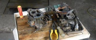
The carburetor on models 2121, 21213 and other cars has basically the same device. Functionally, it is located in the propulsion system, and with its help the fuel is mixed to the state of a combustible mixture. A carburetor, as a rule, consists of several main elements - a float chamber, a so-called jet (with a spray), a diffuser, and a throttle valve. It can have from one to four cameras on different cars, sequential or simultaneous opening of the throttle valves, horizontal, downward or upward movement of the working mixture.
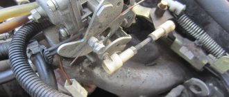
Elements of the carburetor on Niva models
Domestic SUV
The carburetor circuit also includes: a drive lever from the accelerator pump, a diaphragm, an adjusting screw and an air duct from the starter, a shut-off valve (solenoid), an air damper, a needle valve, a fuel supply fitting, an economizer for power modes, a carburetor heating unit, fittings for crankcase ventilation, for supplying vacuum for the vacuum regulator in the ignition, and other elements.
Niva 2121 has the following sequence of passage of fuel elements through the carburetor chamber. First, fuel moves from the fuel tank to the float chamber in a controlled amount. The float rises or falls as the fuel moves.
Further, the fuel path lies through the nozzle into the atomizer, located in the narrow part of the diffuser, with simultaneous air entering the carburetor through the outer pipe. The throttle valves then deliver varying amounts of fuel into the engine cylinder through an intake manifold cast from aluminum alloys. The manifold is attached to the engine with studs through gaskets that have heat-resistant properties.
Main dosing system
Fuel is supplied to the float chamber through strainer 4 (Fig. 2-82) and needle valve 6. From the float chamber, fuel enters through the main fuel jets 9 into the emulsion wells and is mixed with air emerging from the holes of the emulsion tubes 1, which are made integrally with the main air jets. Through nozzles 2, the fuel-air emulsion enters the small and large diffusers of the carburetor.
Rice. 2-82. Diagram of the main dosing systems:
1 – main air jets with emulsion tubes; 2 – nozzles of the first and second chambers; 3 – balancing hole; 4 – fuel filter; 5 – pipe with a calibrated hole for draining part of the fuel into the fuel tank; 6 – needle valve; 7 – float; 8 – throttle valve of the second chamber; 9 – main fuel jets; 10 – throttle valve of the first chamber.
Throttle valves 8 and 10 are connected to each other in such a way that the second chamber begins to open when the first one is already open by 2/3 of the value.
"Solex" and "Ozone"
The VAZ 2121 Niva model can be equipped with an “Ozone” carburetor with the serial designation 2107-110-7010-10 or 2107-110-7010-20. They differ from each other in that the first option has an old-style breaker and does not have a vacuum corrector. The second carburetor does not have a microswitch from the economizer, which affects the environmental friendliness of emissions and has some impact on fuel consumption.
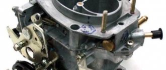
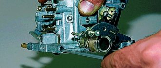
This is the car part
The Niva 21213 is equipped with Solex type carburetors (model 21073-110-7010). They are considered quite “capricious”, which is primarily due to the negligence of the owners themselves. The incorrect operation of the device is primarily affected by low-quality fuel with a large amount of impurities, since in this model the fuel is taken through holes in the bottom of the float chambers (in other models these elements are raised above the bottom).
In addition, problems arise for those “nivovods” who do not promptly change the fuel or air filter, and also do not pay attention to proper cleaning of the carburetor from oil soot emissions through the ventilation system.
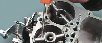
Adjustment of the VAZ carburetor is usually carried out in the float mechanism or in the starting and idle systems. These are very important operations that are best left to the experts.
The float mechanism on the Niva 2121 is adjusted in terms of the position of the floats relative to each other and relative to the walls of the float chamber. In addition, the mechanisms in the open and closed positions of the needle valve may need to be adjusted. In order not to disturb good adjustment, the car owner needs to carefully handle the carburetor cover when removing it, monitor the level of wear of the shut-off cone from the needle (its seat and tongue), as well as the axis of the mounting bracket.
Transition systems
When the carburetor throttle valves are opened before the main metering systems are turned on, the fuel-air mixture enters:
- into the first mixing chamber through the idle jet 2 and the vertical slot 8 of the transition system, located at the level of the edge of the throttle valve in the closed position;
- into the second mixing chamber through outlet 6, located just above the edge of the throttle valve in the closed position. Fuel comes from jet 4 through a tube and is mixed with air from jet 5 entering through the flow channel.
We carry out the adjustment ourselves
Niva 21213 can be subject to adjustment of the starting system by the gap at the edges of the valves, if the carburetor is removed, or by the crankshaft speed directly on the car. In the first case, the gap at the location of the lower edge (in the direction of air movement) from the throttle valve is set to a width of 1.1 mm. It is adjusted with a screw that has a 0.7 cm hexagon on the head and a slot from the shank. This operation is carried out with the cam lever turned counterclockwise from the starting system control (all the way). In the same position, the gap at the lower edge of the air damper is set to 3 mm using a screw in the cover from the diaphragm mechanism in the starting system (you need to loosen the lock nut). At the same time, the rod from the diaphragm must be forcibly recessed completely into the adjusting screw. After adjustment, the screw is fixed with a locknut.
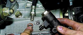
The principle of powering a carburetor engine
Adjusting the Niva starting system directly in the car saves time:
- You need to remove the air filter from the engine, pull the control lever away from the air damper, and start the engine.
- When the air damper is forcibly opened (by touching a flat screwdriver to a third of its full angle of rotation) using a screw (next to the lever on the axis from the throttle valve from the first chamber), the initial rotation speed is set to 2.08.mar.0 thousand rpm (on a warm engine).
- Remove the screwdriver, lower the air damper and, using the screw stop (next to the diaphragm), set the frequency to be 100 rpm lower than the original one (you need to select the appropriate position of the air damper).
- The screw can then be secured using a locknut.
If you have a gas analyzer, then the carburetor adjustment in the starting system part can be done based on the amount of CO (carbon monoxide) in the exhaust gases. If, with the choke control lever fully extended, the gas rate is 8%, then everything is in order. If there is less gas than this value, then the screw on the cover of the diaphragm mechanism is tightened; if there is more, it is unscrewed and repeated measurements are taken.
It is necessary to adjust the idle speed of the Niva 2121 so that there is less carbon monoxide in the exhaust gases and so that the engine runs stably. At service stations, such work is carried out with gas analyzers on the MV. In the garage, adjustments can be made using the tachometer.
Adjusting the device
For these purposes, on a warm engine, a plastic plug is pierced with a screwdriver, then the quality screw is rotated in different directions until the maximum idle speed is reached. Then, using the quantity screw (has a ribbed plastic handle), you need to set an increased speed (50-70 rpm more than at standard idle speed). Operations with screws must be repeated two more times. Then, on models 2121 or 21213, at idle speed, at speeds increased by 50-70 rpm, the quality screw is tightened, and the speed should drop to normal (i.e., decrease by 50-70 revolutions).
Idle system
The idle system takes fuel from the emulsion well after the main fuel jet 7 (Fig. 2-83). Fuel is supplied to fuel nozzle 2 with electromagnetic shut-off valve 1, at the outlet of the nozzle it is mixed with air coming from the flow channel and from the expanding part of the diffuser (to ensure normal operation of the carburetor when switching to idle mode). The emulsion exits under the throttle valve through a hole adjusted by screw 9 for the quality (composition) of the mixture.
Rice. 2-83. Diagram of the idle system and carburetor transition systems:
1 – solenoid shut-off valve; 2 - idle fuel jet; 3 – idle air jet; 4 – fuel nozzle of the transition system of the second chamber with a tube; 5 – air jet of the transition system of the second chamber; 6 – outlet of the transition system of the second chamber; 7 – main fuel systems; 8 – slit of the transition system of the first chamber; 9 – adjusting screw for the quality (composition) of the idle mixture.
Forced idle economizer
The forced idle economizer turns off the idle system during forced idle (while the vehicle is braking, when driving downhill, when changing gears), eliminating the release of carbon monoxide into the atmosphere.
In forced idling mode at a crankshaft speed of more than 2100 rpm and with carburetor limit switch 7 closed to ground (pedal released), shut-off solenoid valve 4 is turned off and the fuel supply is interrupted. If the limit switch is not shorted to ground, the solenoid valve will not turn off.
When the crankshaft rotation speed at forced idle speed decreases to 1900 rpm -1, the control unit turns on the solenoid shut-off valve again, fuel flow begins through the idle jet, and the engine gradually returns to idle speed.
Acceleration pump
The accelerator pump is diaphragm, mechanically driven from cam 6 (Fig. 2-85) on the axis of the throttle valve of the first chamber. When the throttle valve is closed, the spring pulls the diaphragm 3 back, which leads to the filling of the pump cavity with fuel through the ball valve 8. When the throttle valve is opened, the cam acts on the lever 5, and the diaphragm 3 forces fuel through the ball valve 2 and the nozzle 1 into the mixing chamber of the carburetor, enriching flammable mixture.
Rice. 2-85. Accelerator pump diagram:
1 – sprayer; 2 – fuel supply ball valve; 3 – pump diaphragm; 4 - pusher; 5 – drive lever; 6 – pump drive cam; 7 – throttle valve of the first chamber; 8 – check ball valve; 9 – throttle valve of the second chamber.
The pump performance is not adjustable and depends only on the cam profile.
Power mode economizer
The power mode economizer is activated at a certain vacuum behind the throttle valve 5 (Fig. 2-84). Fuel is drawn from the float chamber through ball valve 8. Valve 8 is closed while the diaphragm is held by the vacuum in the intake pipe. When the throttle valve is opened significantly, the vacuum drops slightly and the diaphragm spring 7 opens the valve. The fuel passing through the economizer jet 9 is added to the fuel that passes through the main fuel jet 4, enriching the fuel mixture.
Rice. 2-84. Diagram of power mode economizer and econostat:
1 – throttle valve of the second chamber; 2 – main fuel jet of the second chamber; 3 – econostat fuel jet with tube; 4 – main fuel jet of the first chamber; 5 - throttle valve of the first chamber; 6 – vacuum supply channel; 7 – economizer diaphragm; 8 – ball valve; 9 – economizer fuel jet; 10 – fuel channel; 11 – air damper; 12 – main air jets; 13 – econostat injection tube.