05 February 2015 Lada.Online 923 996 7
The relay and fuse box is also called the mounting block or black box. If problems are identified in the car related to electrical equipment, first check the fuses and relays. If they burn out, we replace them with the same ones, but first we must determine the cause of the burnout.
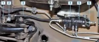
Types of Voltage Regulators
Having understood what types of these devices there are, what their features and properties are, a complete understanding of the procedures carried out during testing will come. This will also give the answer to what scheme, in what way and how to check the generator voltage regulator. There are two types of regulators:
In the first case, it is meant that the regulator housing is combined with the brush assembly directly in the generator housing. In the second case, the regulator is a separate unit, which is located on the car body, in the engine compartment, and wires from the generator go to it, and wires from it go to the battery.
A special feature of the regulators is that their housings are non-separable. They are usually filled with sealant or special resin. And there is no particular point in repairing them, since the device is inexpensive. Therefore, the main problem in this regard is to check the generator voltage regulator relay. Regardless of the type of regulator, the voltage symptoms will be the same.
Device characteristics
This is what the relay looks like
An automobile relay is a switch that serves to close and open sections of electrical circuits at certain levels of electrical and non-electrical input quantities. It acts as a load current switch when the performer, for example, a starter, generator, fan or other structure, consumes more current.
Electric relay device:
- electromagnet - a wire that is wound on a coil with a core of magnetic material;
- anchor - a special plate that controls the contacts;
- switch (switching, opening, closing).
When an electric current passes through the winding of an electric magnet, an electric field arises, pressing the armature to the core, using a pusher to move it, switching the contacts. There are two main types of autovoltage regulator relays used on Zhiguli 2106 cars.
- Non-contact electric relay-regulator type 121.3702. A fairly new unit used by drivers these days, which does not require any settings or additional regulation.
- The magnetic electric regulator with the index PP-380 is an old-style device, currently its production has been suspended, it is not produced as a part for the VAZ 2106.
The interchangeability of the relay allows you, when changing from one type to another, to not have to modify the electrical charging circuit of the machine.
Before you begin replacing the voltage relay, you need to check the functionality of the regulator. You should start the car, and the crankshaft rotation speed should be 2500-3000 rpm. Then you need to turn off all electrical consumers, except the ignition, and measure the voltage at the battery terminals with a voltmeter.
Symptoms of a problem
So, in case of low voltage, the battery simply will not charge. That is, in the morning you will not be able to start the car, the lights on the dashboard may not even light up, or troubles will arise while driving. For example, dim headlights at night, unstable operation of the electrical system (problems with electrical appliances - wipers, heaters, radio, etc.).
In case of increased voltage, there is a high probability of a decrease in the electrolyte level in the battery banks, or its boiling. A white coating may also appear on the battery case. When overcharging, the battery may behave inappropriately.
Signs, malfunctions and repair of the generator and voltage regulator
In addition, you can also identify the following signs of a faulty voltage regulator (in some cases, some of them may or may not be present, it all depends on the specific situation):
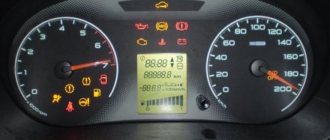
- the control light on the dashboard (although this may be a sign of other malfunctions, for example, that it has burned out, the contact has fallen out, and so on);
- after starting, the battery indicator on the dashboard does not go out, that is, there are obvious malfunctions in charging the battery;
- the brightness of the headlights becomes dependent on the engine speed (you can check this somewhere in a deserted place by placing the car against a wall and accelerating - if the glow changes, then most likely the voltage regulator is faulty);
- the car stopped starting normally the first time;
- The battery is constantly ;
- when the engine speed exceeds 2000 rpm, the indicators on the dashboard turn off ;
- the dynamic characteristics of the car decrease , this is especially noticeable at high engine speeds;
- In some cases, the battery may boil .
Eliminating the causes of charging failure on the VAZ 2106
To check the electrical circuit of a car, you need a simple multimeter or voltmeter. The most common reasons for loss of charging voltage are:
- the generator belt tension is too weak or it is worn out;
- generator malfunction (brush wear, diode bridge malfunction, break or burnout of stator or armature coils);
- voltage regulator malfunction;
- break in the charging circuit.
The most common cause of charging failure is a faulty voltage relay. In order to check its functionality, it will be enough to remove both wires from it, connect them together, and start the engine. Provided that all other elements in the circuit are good, the voltage in the circuit will reach about 17 V or more. If the voltage does not increase, then it is necessary to check the presence of +12 V at the terminal connected to pin 15 of the relay regulator. If it is missing, check the fuse responsible for the circuit and the integrity of this circuit itself.
If there is power at this terminal, then you need to check the connections in the generator excitation circuit. Connect a test lamp between +12 V of the battery and the wire that is connected to terminal 67 of the voltage regulator relay. In this way, you can check the voltage relay-generator circuit, as well as the serviceability of the generator brushes and its armature windings. If there is no voltage at the lamp terminals, an assumption is made that the rectifier bridge is faulty.
Next, check the serviceability of the conductor from the generator to the relay regulator. To do this check, you need to disconnect the terminal from the generator and connect it to -12 V. The glow of the control lamp indicates faulty brushes or broken armature windings. If a generator malfunction is suspected, it is removed from the vehicle and completely disassembled. Next, the serviceability of each diode in the diode bridge of the generator is checked, and the stator and armature coils are tested for breakage or burnout. Faulty elements are repaired or replaced.
The VAZ 2106 battery charging circuit provides for a constant voltage of 13.5 to 14.3 V, regardless of engine speed. However, there are cases when, at medium engine speeds, the voltage noticeably “drops” when an additional load is turned on. If such a phenomenon occurs, it is necessary to check the tension of the generator belt and adjust it. Poor contact at the battery terminals sometimes also leads to this effect.
If the voltage at the battery terminals is higher than the specified limits, you need to check all contacts, starting from the positive terminal of the battery to the voltage regulator relay. If all contacts are normal, then the relay regulator must be replaced.
Timely care of your car's electrical equipment, the condition of the battery contacts and terminals, and regular checking of the belt tension and electrolyte level in the battery will allow your car's engine to operate for a long time and without problems, and you will avoid many malfunctions on the road.
Reasons for failure of the relay regulator
The reasons for the failure of the voltage regulator may be:
- short circuit in the circuit, including interturn short circuit of the excitation winding;
- failure of the rectifier bridge (diode breakdown);
- reverse polarity or incorrect connection to the battery terminals;
- penetration of moisture into the housing of the regulator and/or generator (for example, when washing a car or driving in heavy rain);
- mechanical damage to the unit;
- natural wear and tear of the unit, including brushes;
- poor quality of the device being directly tested.
There are a number of simple methods for checking the regulator, regardless of whether the unit is removable or not.
Internal regulator VAZ 2107
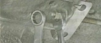
Replacing the internal relay may be difficult, since it is installed on the back of the generator, and access to it is somewhat complicated. Despite this, replacement is carried out even without removing the generator, directly on the car. It is screwed to the body with two screws. Replacing the timing belt on a VAZ 2112 with your own. Installing a new regulator relay on a VAZ 2107. Replacing the regulator relay with generator ground. By unscrewing these screws with a Phillips screwdriver and disconnecting the terminal, you can remove it and replace it with a new one.
The simplest way to check the generator voltage regulator
The simplest method of checking the regulator is to measure the voltage at the battery terminals with a multimeter. However, it is worth immediately making a reservation that the algorithm given below does not give a 100% probability of failure of the regulator. Perhaps the generator itself has failed. But the advantage of this method is that it is simple and there is no need to dismantle the device from the car. So, the algorithm for checking the generator voltage regulator with a multimeter is as follows:
- Set the tester to DC voltage measurement mode at a limit of about 20 V (depending on the specific model, the main thing is that it displays values up to 20 V as accurately as possible).
- Start the engine.
- Measure the voltage at the battery terminals in idle mode (1000. 1500 rpm). If the regulator and generator are working properly, the value should be within 13.2. 14 V.
- Increase the speed to 2000. 2500 rpm. In the normal state of the electrical circuit, the corresponding voltage will increase to 13.6. 14.2 V.
- When the speed increases to 3500 rpm and above, the voltage should not exceed 14.5 V.
If during the test the voltage values are very different from those given, then most likely the machine’s voltage regulator is faulty. Remember that the voltage should not fall below 12V and should not rise above 14.5V.
As mentioned above, the regulator can be separate or combined with a generator. Currently, almost all foreign cars, and most modern domestic cars, have combined relays installed. This is due to the specifics of their work and space saving.
Block in the cabin
On cars of all years of production, it is located near the driver’s left foot and is covered with a plastic panel.
Appearance
The diagrams and their explanation are given below. The LADA Granta cigarette lighter fuse is designated as follows:
- 2011-2014 in: F20;
- 2015: F18;
- 2016, 2022: F27;
- 2018 - present v.: F25
For cars assembled in 2011-2014
Circuit breakers
| Designation | Denomination, A | Protected element |
| F1 | 15 | Controller; Cooling fan; Ignition coil; Injectors |
| F2 | 30 | Power window motors |
| F3 | 15 | Alarm |
| F4 | 20 | Windshield wiper, airbags |
| F5 | 7.5 | Ignition switch (pin 15) |
| F6 | 7.5 | Reversing lamp in the right rear lamp |
| F7 | 7.5 | Canister purge valve; Sensors: mass air flow, vehicle speed, oxygen concentration |
| F8 | 25 | Rear window heating element |
| F9 | 5 | Side lights (right side) |
| F10 | 5 | Side lights (left side); Illumination of the instrument cluster and switches on the instrument panel |
| F11 | 5 | Fog lamp in the left rear light |
| F12 | 7.5 | Low beam headlights, right headlight |
| F13 | 7.5 | Low beam headlights, left headlight |
| F14 | 10 | High beam headlights, right headlight |
| F15 | 10 | High beam headlights, left headlight |
| F16 | – | Not used (until 2013) |
| 10 | PTF right (since 2013) | |
| F17 | – | Not used (until 2013) |
| 10 | PTF left (since 2013) | |
| F18 | – | Not used (until 2013) |
| 15 | Heated seats (since 2013) | |
| F19 | – | Not used (until 2013) |
| 10 | ABS/ESC | |
| F20 | 15 | Sound signal; Instrument cluster; Cigarette lighter; Diagnostic connector; Electric trunk lock |
| F21 | 15 | Fuel pump |
| F22 | 15 | central locking |
| F23 | 10 | Daytime Running Lights |
| F24 | – | Not used (reserve) |
| F25 | 10 | Main and additional brake lights; Interior lighting |
| F26 | – | Not used (reserve) |
| F27 - F30 | – | Spare fuse |
| F31 | – | Not used (reserve) |
| F32 | 30 | Heater fan motor and electric power steering control circuits |
Relay
| Designation | Protected element |
| K1 | Cooling fan motor |
| K2 | Power window motors |
| K3 | Starter |
| K4 | Low and high beam headlights; Daytime Running Lights; Heated rear window; Heater fan motor; Windshield cleaner and washer |
| K5 | Turn signal lamps |
| K6 | Windshield wiper motor |
| K7 | High beam headlights |
| K8 | Sound signal |
| K9 | dipped headlights |
| K10 | Heated rear window |
| K11 | Engine ECU |
| K12 | Fuel pump |
For cars assembled in 2015
In 2015, there were 2 versions of the interior fuse box in the LADA Granta: from ABAR and Delphi. Their diagrams and explanations are given below.
AVAR block diagram
Delphi block diagram
Circuit breakers
| Designation | Denomination, A | Protected Circuits |
| F1 | 15 | Ignition coils; Injectors; Engine Control System Controller |
| F2 | 5(1) | Daytime Running Lights |
| 25(2) | Central body electronics unit; Driver door module | |
| F3 | 10(1) | Alarm |
| 10(2) | Automatic transmission control controller; Automatic gearbox control drive | |
| F4 | 10 | Airbag system controller |
| F5 | 7.5 | Terminal 15 devices |
| F6 | 7.5(1) | Reversing light; Direction indicators |
| 7,5(2) | Reversing light; Automatic transmission control controller; Safe parking system control unit | |
| F7 | 7.5 | Canister purge valve; Sensors: mass air flow/pressure, phases, oxygen concentration |
| F8 | 25 | Heated rear window(1) Heated rear window and outside mirrors(2) |
| F9 | 5 | Side lights (right side) |
| F10 | 5 | Side lights (left side); Illumination of instruments and keys; License plate lights; Luggage and glove box lighting |
| F11 | 5 | Rear fog lights |
| F12 | 10 | Low beam (right headlight); Electrical corrector for right headlight |
| F13 | 10 | Low beam (left headlight); Left headlight electric corrector |
| F14 | 10 | High beam (right headlight) |
| F15 | 10 | High beam (left headlight) |
| F16 | 10 | Fog lights, right(2) |
| F17 | 10 | Fog lights, left(2) |
| F18 | 20 | Front seat heaters; Cigarette lighter |
| F19 | 15 | Door locking motors(1) |
| 5 | ABS(2) | |
| F20 | 15 | Sound signal |
| F21 | 10 | Fuel pump |
| F22 | 15(1) | Washers, windshield and rear window cleaners; |
| 25(2) | Central body electronics unit; | |
| F22 | 25(2) | Central body electronics unit; Washer, rear window cleaner |
| F23 | 5 | Instrument cluster; Diagnostic connector |
| F24 | 7.5(2) | Air conditioning compressor clutch; Automatic climate control system controller |
| F25 | 7.5(1) | Brake signals; Interior lighting |
| 7,5(2) | Brake signals | |
| F26 | 10(2) | Central body electronics unit |
| F31 (for the pre-function block AVAR) F27 (for the pre-function block Delphi) | 30 | Power windows for front doors(1) |
| 25 | ABS(2) | |
| F32 (for the pre-function block AVAR) F28 (for the pre-function block Delphi) | 30(1) | Electric heater fan |
| 30(2) | Electric heater fan; Automatic climate control system controller |
Relay
| Designation | Protected Circuits |
| K1 | Electric radiator cooling fans |
| K2 | Power windows(1) Electric radiator cooling fans(2) |
| K3 | Additional starter relay |
| K4 | Ignition switch unloading relay |
| K5 | Turn signals and hazard warning lights(1) |
| K6 | Windshield wiper(1) Heated seats(2) |
| K7 | High beam headlights |
| K8 | Sound signal |
| K9 | dipped headlights |
| K10 | Heated rear window; Heated exterior mirrors(2) |
| K11 | Engine ECU |
| K12 | Fuel pump |
| K13 | Additional hazard warning lights(1) Reversing lights(2) |
| K14 | Additional hazard warning lights(1) Electric radiator cooling fans(2) |
| K15 | Heated windshield(2) |
| K16 | |
| K17 | A/C electromagnetic clutch(2) |
Note to the table:
- (1): “Standard” package;
- (2): “Norma”, “Lux” configurations.
For cars assembled in 2016, 2022
Circuit breakers
| Designation | Denomination, A | Protected Circuits |
| F1 | 15 | Ignition coils; Injectors; Engine Control System Controller |
| F2 | 30 | Central body electronics unit(3) |
| F3 | 15(1),(2) | Alarm |
| 10(3) | Central body electronics unit; Light switch | |
| F4 | 20(1),(2) | Windshield washer and wiper |
| 15(3) | Airbags; Rain sensor | |
| F5 | 7.5 | Terminal 15 devices |
| F6 | 7.5(1),(2) | Reversing light; Direction indicators |
| 7.5(3) | Reversing light; Safe parking system | |
| F7 | 7.5 | Canister purge valve; Sensors: mass air flow/pressure, phases, oxygen concentration; Tire pressure monitoring system(2),(3) |
| F8 | – | Reserve |
| F9 | 5 | Side lights (right side) |
| F10 | 5 | Side lights (left side); Illumination of instruments and keys; License plate lights; Trunk lighting; Glove compartment lighting(2),(3) |
| F11 | 5 | Rear fog lights |
| F12 | 10 | Low beam headlights (right headlight) |
| F13 | 10 | Low beam headlights (left headlight) |
| F14 | 15 | Cartridge for connecting additional devices in the trunk |
| F15 | 10 | Rear window wiper and washer (optional) |
| F16 | 5 | Driver door module(3) |
| F17-F20 | – | Reserve |
| F21 | 10 | High beam headlights (left headlight) |
| F22 | 10 | High beam headlights (right headlight) |
| F23 | 10 | Fog lamp (right) |
| F24 | 10 | Fog lamp (left) |
| F25 | 15 | Heated front seats(2),(3) |
| F26 | 5 | ABS/ECS |
| F27 | 15 | Cigarette lighter |
| F28 | 15 | Fuel pump |
| F29 | 15 | Motor gearboxes for locking doors and trunk(1),(2) |
| 20 | Central body electronics unit; windshield cleaner and washer(3) | |
| F30 | 10 | Daytime running lights(1),(2) |
| F31 | 7.5 | A/C compressor clutch(2),(3) |
| F32 | 7.5 | Brake signal; Automatic transmission control controller(2),(3); Interior lighting(1),(2) |
| F33 | 25 | ABS/ECS |
| F34 | 5 | Instrument cluster; Diagnostic connector |
| F35 | 15 | Airbags(1),(2) |
| F36 | 10 | Sound signal |
| F37 | 10 | Multimedia system |
| F38-F40 | – | Reserve |
| F41 | 50 | Heated windshield(2),(3) |
| F42 | 30 | Power windows for front doors(2) |
| F43 | 50 | Robotic gearbox control controller |
| F44 | 30 | Electric heater fan; Air conditioning control system controller(2),(3) |
| F45 | 25 | Heated rear window Heated outside mirrors(2),(3) |
| F46 | – | Reserve |
Relay
| Designation | Protected Circuits |
| K1 | Ignition switch unloading relay |
| K2 | Starter |
| K3 | Windshield wiper(1),(2); Radiator cooling fan(3) |
| K4 | Electric radiator cooling fan; Turn signals and hazard warning lights(1),(2) |
| K5 | A/C compressor clutch(3) |
| K6 | Front power windows(2) Heated rear window and outside mirrors(3) |
| K7 | High beam headlights |
| K8 | Sound signal |
| K9 | dipped headlights |
| K10 | Reversing light(2),(3) |
| K11 | Engine ECU |
| K12 | Fuel pump |
| K13 | Heated seats(2),(3) |
| K14 | Heated windshield(2),(3) |
| K15 | Heated rear window and exterior mirrors(1),(2) |
| K16 | A/C compressor clutch(2) |
| K17 | Reserve |
| K18 | Radiator cooling fan(2) |
Note on tables:
- (1): “Standard” package;
- (2): “Norma” package;
- (3): “Lux” package.
For cars assembled from 2022
Circuit breakers
| Designation | Denomination, A | Protected element |
| F1 | 15 | Electric radiator fan (minimum speed) (version with air conditioning or climate control system); Electric radiator fan (maximum speed); Air conditioning compressor clutch (cars with air conditioning or climate control); Engine ECU; Injectors; Ignition coils 2×2 (for 8-valve internal combustion engines); Ignition coils (for 16-valve internal combustion engines) |
| F2 | 7.5 | Intake pipe damper valve (for engine 21127); Canister purge valve; Oxygen, phase sensors (for 16-valve engines), mass air flow (for 8-valve internal combustion engines or 16-valve engines 21126); AMT selector (version with AMT controller); Tire pressure monitoring system |
| F3 | 5 | ABS/ECS |
| F4 | 15 | Airbags |
| F5 | 7.5 | Automatic Transmission Starter/Controller; Ignition switch unloading relay; Heated windshield and rear window; Seat heating; Fuel pump; ECU for electrically heated windshield; Engine ECU; Audio system; Electric power steering ECU; Wiper switch; Central body electronics unit; Terminal block "ERA-GLONASS"; Clutch pedal switch (for manual transmission); Brake pedal switch; Instrument cluster; Door lock system; Driver's door lock switch; Air conditioner switch; Automatic transmission speed sensor; Automatic transmission mode switch; AMT controller; Tire pressure monitoring system |
| F6 | 7.5 | Reversing light; Direction indicators; Parking system ECU |
| F7 | 10 | High beam (right) |
| F8 | 10 | High beam (left |
| F9 | 5 | Side lights (right side) |
| F10 | 5 | Side lights (left side); License plate lights; Trunk light; Illumination of instruments and keys |
| F11 | 5 | Rear fog lights |
| F12 | 10 | Low beam (right); Electric headlight corrector |
| F13 | 10 | Low beam (left); Electric headlight corrector |
| F14 | 20A | Central body electronics unit; Cleaner, windshield washer; Steering column wiper switch |
| F15 | 10 | Cleaner, rear window washer |
| F16 | 5 | Audio system; Ignition switch unloading relay |
| F17 | 5 | Door lock system |
| F18 | 5 | Heated mirrors |
| F19, F20 | – | Reserve |
| F21 | 15 | Fuel pump |
| F22 | 7.5 | Brake light switch |
| F22 | 7.5 | Main and additional brake lights; ABS/ECS; AMT controller |
| F23 | 5 | Instrument cluster; Diagnostic connector |
| F24 | 10 | Sound signal |
| F25 | 15 | Cartridge for connecting additional consumers in the passenger compartment/Cigarette lighter |
| F26 | 5 | Terminal block "ERA-GLONASS" |
| F27 | 10 | Fog lamp (right) |
| F28 | 10 | Fog lamp (left) |
| F29 | 15 | Heated front seats |
| F30 | 10 | Audio system |
| F31 | 10 | Direction indicators; Power supply for body electronics unit; Daytime Running Lights |
| F32 | 30 | Central body electronics unit: electric windows; Door and trunk locks; Rain sensor; Interior, glove box and trunk lighting |
| F33 | 5 | Driver door module |
| F34 | 7.5 | Air conditioning compressor clutch (version with air conditioning or climate control system); Automatic climate control system controller |
| F35 | 15 | Automatic transmission controller; Automatic transmission control drive |
| F36 | 15 | Alarm |
| F37 | 15 | Trunk lock actuator switch; Trunk lock actuator control relay; Trunk lighting; Door lock control unit |
| 5 | Trunk lock actuator switch; Trunk lighting | |
| 25 | Trunk lock actuator switch; Trunk lock actuator control relay; Trunk lighting; Door lock control unit | |
| F38 | 10 | Daytime Running Lights |
| F39 | 15 | Cartridge for connecting additional consumers in the trunk |
| F40 | 10 | Trailer |
| F41 | 50 | Heated windshield |
| F42 | 30 | Heated rear window and exterior mirrors |
| F43 | 50 | AMT controller |
| F44 | 30 | Electric heater fan; Automatic climate control system controller |
| F45 | 30 | Power windows for front doors; Exterior mirror control |
| F46 | – | Reserve |
Relay
| No. on the diagram | Denomination, A | Purpose |
| K1 | 50A | Ignition switch unloading relay |
| K2 | 30A | Starter |
| K3 | 30A | Windshield wiper; Autostart (optional) |
| K4 | 30A | Electric radiator fan of maximum speed (optional) |
| K5 | 30A | Turns and hazard warning lights; K15A (autostart) (in variant version) |
| K6 | 30A | Heated rear window |
| K7 | 20A | High beam headlights |
| K8 | 20A | Sound signal |
| K9 | 20A | dipped headlights |
| K10 | 20A | Air conditioning compressor clutch (version with air conditioning or climate control) |
| K11 | 20A | ECM main relay |
| K12 | 20A | Fuel pump |
| K13 | 20A | Heated seats (optional) |
| K14 | 70A | Heated windshield (optional) |
| K15 | 20A | Turning on the alarm |
| K16 | 30A | Alarm power supply; Turning on the reverse lamp (optional) |
| K17 | 30A | Electric windows; Radiator fan in autostart mode (optional) |
| K18 | 30A | Minimum speed radiator fan (optional) |
Checking the combined relay-regulator
Checking the VAZ 2110 voltage regulator
To perform the corresponding check, it is necessary to assemble the circuit shown in the figure. To do this, use a charger or power supply with an adjustable load (it is important that it be used to regulate the voltage value in the circuit), a 12 V light bulb (for example, from a turn signal or headlight, with a power of 3.4 W), a multimeter, and the regulator itself voltage (this can be from a Bosch, Valeo or other generator). It is advisable to have the wires used for switching with “crocodiles”.
Reasons for lack of charging and their diagnosis
Six generator brushes
Wear of generator brushes. If the brushes of the VAZ 2106 generator are not long enough, charging becomes low and may disappear completely. Checking the technical condition of spare parts should begin with a thorough inspection of the generator brush. The length of the brushes cannot be less than 12 mm. If it is smaller, the part needs to be replaced.
Checking an Individual Regulator
Checking the voltage regulator of the G-222 generator: 1 - battery; 2 - voltage regulator; 3 - control lamp.
As a rule, separate voltage regulators were installed on old cars, including domestic VAZs. But some manufacturers continue to do this to this day. The verification process is similar. To do this, you need to have a power supply with a voltage regulator, a 12 V light bulb, a multimeter and a directly tested regulator.
To check, you need to assemble the circuit shown in the figure. The process itself is similar to the one above. In normal condition (at a voltage of 12 V), the light bulb lights up. When the voltage value increases to 14.5 V, it goes out, and when it decreases, it lights up again. If during the process the lamp lights up or goes out at other values, it means that the regulator has failed.
Checking relay type 591.3702-01
Relay test diagram type 591.3702-01
You can also still find a voltage regulator of type 591.3702-01, which was installed on rear-wheel drive VAZs (from VAZ 2101 to VAZ 2107), GAZ and Moskvich. The device is mounted separately and installed on the body. In general, the test is similar to that described above, but the differences are in the contacts used.
In particular, it has two main contacts - “67” and “15”. The first of them is a minus, and the second is a plus. Accordingly, to check it is necessary to assemble the circuit shown in the figure. The verification principle remains the same. In normal condition, at a voltage of 12 V, the light bulb lights up, and when the corresponding value increases to 14.5 V, it goes out. When the value returns to its original value, the light comes on again.
A classic regulator of this type is a device of the PP-380 brand, installed on VAZ 2101 and VAZ 2102 cars. We provide reference data regarding this regulator.
| Adjustable voltage at regulator and ambient temperature (50±3)° C, V: | |
| at the first stage | no more than 0.7 |
| on the second stage | 14,2 ± 0,3 |
| Resistance between plug “15” and ground, Ohm | 17,7 ± 2 |
| Resistance between plug “15” and plug “67” with open contacts, Ohm | 5,65 ± 0,3 |
| Air gap between armature and core, mm | 1,4 ± 0,07 |
| Distance between second stage contacts, mm | 0,45 ± 0,1 |
Testing a three-level relay
Regulated power supply
Some car owners install on their cars, instead of standard “chocolate bars,” three-level relays, which are technologically more advanced. Their difference is the presence of three voltage levels at which the battery power is cut off (for example, 13.7 V, 14.2 V and 14.7 V). The appropriate level can be set manually using a special regulator.
Such relays are more reliable and allow flexible adjustment of the cutoff voltage level. As for checking such a regulator, it is completely similar to the procedures described above. Just do not forget about the value that is set on the relay, and accordingly, check it with a multimeter.
Generator check
There is one method by which you can check the performance of a car generator equipped with a regulator relay 591.3702-01 with diagnostic elements. It is as follows:
- disconnect the wires that went to pins 67 and 15 of the voltage regulator;
- connect a light bulb to it (excluding the regulator from the circuit);
- Remove the wire from the positive terminal of the battery.
If, as a result of these actions, the engine does not stall, then we can say that the car’s generator is in order. Otherwise, it is faulty and needs to be checked and replaced.
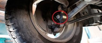
Where are the fuses for the Lada Granta?
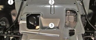
The fuse box is located near the driver's left foot. To open the lid, pull the lower left corner of the lid (No. 1) and release the left locking point, then the middle one (No. 2) and the two right locking points (No. 3 and 6). Then release the top points (No. 4 and 5) and remove the cover.
Installing the mounting block cover is done in the following order: first snap the right side of the cover, then the lower ones, and then the upper ones. Make sure that the fastening elements of the cover are aligned exactly with the metal fasteners.
There are symbols on the plastic cover of the mounting block that indicate what each fuse (F) and relay (K) does.
Recommendations for increasing the service life of the regulator
In order to increase the service life of the voltage regulator, it is necessary to adhere to several simple rules aimed at implementing preventive measures. Among them:
- do not allow excessive contamination of the generator, periodically inspect its condition, and, if necessary, dismantle and clean the unit;
- check the tension of the alternator belt, tighten it if necessary (either yourself or in a car service);
- monitor the condition of the generator windings, in particular, do not allow them to darken;
- check the contact on the control wire of the relay-regulator, both its quality and the presence of oxidation on it;
- Perform periodic voltage checks on the vehicle battery with the engine running.
Following these simple rules will allow you to increase the resource and service life of both the generator and the vehicle voltage regulator.
Results
Checking the voltage regulator relay is not a difficult task, and almost any car enthusiast with basic repair skills can handle it. The main thing is to have the appropriate tools for this - a multimeter, a power supply with a voltage regulator (although you can connect it to a battery with a charger), a 12 V lamp and pieces of wires for mounting the appropriate circuit.
If during the inspection you find out that the regulator is out of order, then it must be replaced (repair work is usually not carried out). The main thing is not to make a mistake when choosing it and purchase the part that is suitable specifically for your car.
| Home Auto Electronics Voltage regulators for automobile alternators |
Rice. 1. Methods of controlling the excitation current: G - generator with parallel excitation; Wв — excitation winding; Rd - additional resistance; R - ballast resistance; K - current switch (regulating body) in the excitation circuit; a, b, c, d, e are indicated in the text.
A modern automobile internal combustion engine (ICE) operates over a wide speed range (900–6500 rpm). Accordingly, the rotor speed of the automobile generator changes, and therefore its output voltage.
Generator brushes.
Generator brushes are a part that is found in almost every generator.
The more modern the car, especially a foreign car, the more electrical consumers it has, which in one way or another make life easier for the car owner. Accordingly, an increasingly important role among automobile units is played by the autogenerator, which supplies electricity to all consumers in the car.
What are generator brushes used for?
Using the generator brushes, the voltage from the regulator relay is supplied to the excitation winding - the rotor. The rotor has commutator rings attached to it - the rotor commutator to which the brushes fit tightly. To transfer current from the voltage relay to the rotor winding, the brushes must be in a certain position and pressed against the commutator rings with a certain force. To do this, they are installed in the seats of the brush holder and are pressed by a spring on the reverse side.
The material from which the brushes of foreign manufacturers' generators are made - a mixture of copper and graphite - differs from domestic ones in better wear resistance and conductivity. For this reason, it is not recommended to install this element on foreign cars from domestic cars.
How do you know when you need to replace your generator brushes?
- Car mileage, 150-200 thousand km. is the period when the part is worn out.
- The battery charging indicator light comes on and goes off again. This may continue for several days until the icon lights up completely.
- Loss of power or voltage drop due to a loose fit of a worn part.
- Voltage surges in the vehicle's on-board network may indicate a faulty part.
- If a lot of motor oil or other technical fluid gets on the generator, then the part is subject to increased wear.
How to check whether replacing the generator brushes is really necessary?
To determine the causes of the malfunction, it is necessary to disassemble the generator and inspect the generator brushes - they must be long enough and in contact with the slip rings.
If the remaining length of at least one element is less than 3 mm, replacement is necessary in any case. Also, the generator brushes must be well movable in their seats, have approximately equal residual length, must not be dirty, and the springs must press with the same force.
How to replace brushes on a generator? Procedure.
On many modern autogenerators, the brushes are integral with the voltage regulator relay, for example, this is true for Valeo, Bosch, Mitsubishi, Magneti Marelli; for Denso, the relay regulator is made separately from the brush assembly.
To replace the generator brushes , if they are built into the regulator relay, the tools you will need are a 40-100 W soldering iron, solder, flux, a 1.5-3 mm drill, a drill or screwdriver, as well as a tool for removing the regulator.
Voltage regulation in generators with electromagnetic excitation
Methods of regulation
. If the main magnetic field of the generator is induced by electromagnetic excitation, then the electromotive force Eg of the generator can be a function of two variables: the rotor rotation frequency n and the current Ib in the excitation winding - Eg = f(n, Ib).
It is this type of excitation that takes place in all modern automobile alternating current generators that operate with a parallel excitation winding.
When the generator operates without load, its voltage Ug is equal to its electromotive force EMF Eg: Ug = Eg = SFn (1).
The voltage Ug of the generator under the load current In is less than the emf Eg by the value of the voltage drop across the internal resistance rg of the generator, i.e. we can write that Eg = Ug + Inrg = Ug(1 + β) (2).
The value β = Inr/Ug is called the load factor.
From a comparison of formulas 1 and 2 it follows that the generator voltage Ug = nSF/(1 + β), (3) where C is a constant design factor.
Equation (3) shows that both at different frequencies (n) of rotation of the generator rotor (n = Var), and with a changing load (β = Var), the constant voltage Ug of the generator can be obtained only by a corresponding change in the magnetic flux F.
The magnetic flux Ф in a generator with electromagnetic excitation is formed by the magnetomotive force Fв = W Iв of the excitation winding Wв (W is the number of turns of the winding Wв) and can be easily controlled using the current Iв in the excitation winding, i.e. Ф = f (Iв). Then Ug = f[n, β, f(Iv)] 1, which allows you to keep the voltage Ug of the generator within the specified control limits for any changes in its speed and load by appropriately selecting the regulation function f(Iv).
The automatic regulation function f(Iв) in voltage regulators comes down to reducing the maximum value of the current Iв in the excitation winding, which occurs when Iв = Uг/Rw (Rw is the active resistance of the excitation winding) and can be reduced in several ways (Fig. 1): by connecting to winding Wв in parallel (a) or in series (b) with additional resistance Rд: by short-circuiting the excitation winding (c); rupture of the excitation current circuit (d). The current through the excitation winding can be increased by short-circuiting the additional series resistance (b).
All these methods change the excitation current in steps, i.e. There is intermittent (discrete) current regulation. In principle, analogue regulation is also possible, in which the value of the additional series resistance in the excitation circuit changes smoothly (d).
But in all cases, the generator voltage Ug is kept within the specified control limits by corresponding automatic adjustment of the excitation current value.
Discrete - pulse control
In modern automobile generators, the magnetomotive force Fb of the excitation winding, and hence the magnetic flux F, is changed by periodic interruption or an abrupt decrease in the excitation current Ib with a controlled interruption frequency, i.e. discrete pulse regulation of the operating voltage Ug of the generator is used (previously analog regulation was used, for example, in carbon voltage regulators).
The essence of discrete-pulse regulation will become clear from a consideration of the principle of operation of a generator set, consisting of a simple contact-vibration voltage regulator and an alternating current generator (ACG).
Rice. 2. Functional (a) and electrical (b) diagrams of a generator set with a vibration voltage regulator.
A functional diagram of a generator set operating in conjunction with an on-board battery (AB) is shown in Fig. 2a, and the electrical diagram is in Fig. 26.
The generator consists of: phase windings Wph on the stator ST, a rotating rotor R, a power rectifier VP on semiconductor diodes VD, an excitation winding Wв (with active resistance Rw). The generator rotor receives mechanical rotational energy Am = f(n) from the internal combustion engine. The vibration voltage regulator RN is made on an electromagnetic relay and includes a switching element CE and a measuring element IE.
The FE switching element is a vibrating electrical contact K, which makes or breaks an additional resistance Rd, which is connected in series with the excitation winding Wb of the generator. When the switching element is triggered (opening contact K), a signal τRд is generated at its output (Fig. 2a).
The measuring element (IE, in Fig. 2a) is that part of the electromagnetic relay that implements three functions:
- comparison function (CS) of the mechanical elastic force Fn of the return spring P with the magnetomotive force Fs = WsIs of the relay winding S (Ws is the number of turns of the winding S, Is is the current in the relay winding), and the result of the comparison is the period T formed in the gap with = tр + tз) armature oscillations N;
- the function of the sensitive element (SE) in the feedback circuit (DSP) of the voltage regulator, the sensitive element in vibration regulators is the winding S of the electromagnetic relay, connected directly to the voltage Ug of the generator and to the battery (to the latter through the ignition key VZ);
- the function of a master device (SD), which is implemented using a return spring P with an elastic force Fп and a support force Fо.
The operation of a voltage regulator with an electromagnetic relay can be clearly explained using the speed characteristics of the generator (Fig. 3 and 4).
Rice. 3. Change in Ug, Iv, Rb over time t: a - dependence of the current value of the generator output voltage on time t - Ug = f (t); b - dependence of the current value in the excitation winding on time - Iв = f (t); c - dependence of the arithmetic mean value of the resistance in the excitation circuit on time t - Rb = f(t); I is the time corresponding to the frequency (n) of rotation of the generator rotor.
While the voltage Ug of the generator is lower than the voltage Ub of the battery (Ug Ub), the magnetomotive force Fs of the relay winding becomes greater than the force Fp of the return spring P, i.e. Fs= Is Ws > Fп. The electromagnetic relay is activated and contact K opens, and additional resistance is connected to the excitation winding circuit.
Even before contact K opens, the current Iв in the excitation winding reaches its maximum value Iв max = UгRw > Iвб, from which, immediately after contact K opens, it begins to fall, tending to its minimum value Iв min = Uг/(Rw + Rд). Following the drop in the excitation current, the generator voltage begins to decrease accordingly (Ug = f(Iv), which leads to a drop in the current Is = Ug/Rs in the relay winding S and contact K is opened again by the force of the return spring P (Fp > Fs). By the time of opening contact K, the generator voltage Ug becomes equal to its minimum value Umin, but remains slightly higher than the battery voltage (Ugmin > Ub).
Replacing generator brushes for Lada Granta (VAZ Granta)
You will need: a flat blade screwdriver, 8”, 12” wrenches, “7”, “8”, “24” socket wrenches, hammer, soldering iron, DC voltmeter, megger. The operation of the voltage regulator is to continuously automatically change the excitation current of the generator so that the generator voltage is maintained within specified limits when the rotation speed and load current change.
If necessary, you can check and replace the voltage regulator without removing the generator from the Lada Granta.