Detailed color diagrams of the VAZ 2114 wiring (carburetor, injector) are provided with a description of the electrical equipment for various modifications.
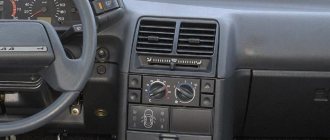
The information is intended for self-repair of cars. Many electrical circuits are divided into several sections for ease of viewing via a computer or smartphone; there are also circuits in the form of one picture with a description of the elements - for printing on a printer. The VAZ 2114 (Samara-2) car is built on the VAZ 21093 platform and is an improved version of it. The first prototype of the hatchback was assembled back in 2000. A year later, the Volzhsky Automobile Plant produced the first pilot batch of 50 VAZ-2114 cars, and in the same 2001 the hatchback was first introduced to the market. The interior features a new instrument panel, a new steering wheel, an adjustable steering column, power windows and a new heater. Years of production 2114: 2001—2013
The fourteenth model was previously equipped with a 1.5 liter eight-valve engine, borrowed from the VAZ 2111 model with an injector. A little later it was replaced by the VAZ 11183-1000 version, which complies with the Euro-3 standard. The VAZ 2114 injector received a more powerful engine, and this is one of the reasons that the wiring of the 2114 has also changed.
A wiring harness has been added for connecting to the electronic switch. A harness has also appeared for connecting to the ignition module terminal.
Replacing high-voltage wires will require additional attention, because the connection procedure depends on the year of manufacture of the car. Until 2004, 4-pin ignition modules were installed, and after that - 3-pin. Connecting the adsorber valve to the injection system controller also provided another additional element. An adsorber is an electromechanical device used for ventilation and removal of condensate in a gas tank. Complications also affected the interior part. The dashboard received improvements in the form of the appearance of a BC (on-board computer), a new instrument panel and a change in the position of the glove compartment.
Car modifications 2114
VAZ-21140 . Modification with an 8-valve injection engine VAZ-2111, 1.5 liters and 77 horsepower. Serial production from 2003 to 2007
VAZ-21144 . Modification with an 8-valve VAZ-21114 engine, 1.6 liters and 81.6 horsepower. Years of serial production: 2007-2013.
VAZ-211440 . Another modification released in 2007, it was equipped with a VAZ-11183 engine with a volume of 1.6 liters and a power of 82 horsepower. The car was discontinued in 2013.
VAZ-211440-24 . Released in 2009, a modification with an injection 16-valve VAZ-21124 engine with a volume of 1.6 liters and a power of 89.1 horsepower. Discontinued in 2013.
VAZ-211440-26 . Modification with a 16-valve injection engine VAZ-21126, which complies with the Euro-3 environmental standard, with a volume of 1.6 liters and a power of 98 hp. The car was produced from 2010 to 2013.
Repair and replacement of faulty stove elements
It is completely impractical to change the VAZ 2113–15 stove. First of all, this is quite expensive - buying a new stove without a tap and pipes will cost 4-5 thousand rubles. Moreover, replacing the heater is very labor-intensive - you will need to completely remove and then reinstall the panel. The job may take a full day and will require an assistant. It is much easier to identify the faulty element and replace only it.
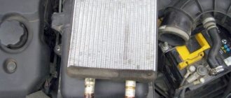
Restoring the stove radiator
If a stove radiator is clogged from the inside, you can try to clean it of scale and deposits with various household cleaning products, such as Comet, Krot, Silit, or other chemically active substances. Some car owners use Coca-Cola for this purpose.
It is better to carry out the flushing procedure with the radiator removed, but you can do without dismantling it. To do this, drain the coolant from the system, remove the pipes from the radiator and pour a cleaning agent inside. Then the engine starts, the heater turns on and runs for several hours. After this, the radiator is thoroughly washed by connecting a hose with running water to it and dried with compressed air.
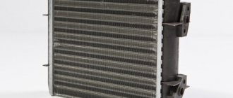
In the event of a leak, restoring the radiator is much more difficult. This can be done by soldering. However, most radiators are made of aluminum, damage in which can only be soldered with a powerful soldering iron using special fluxes and solders. But even in this case, there will be no guarantee that the radiator will be fully operational. It is much easier to replace it - a new product for the VAZ 2113-15 costs about a thousand rubles.
Replacing a stove radiator without removing the panel
The VAZ 2113–15 instruction manual states that access to the radiator can only be achieved after dismantling the panel. However, craftsmen came up with an algorithm for replacing the radiator with only partial disconnection of the panel from the body. To do this you will need:
- crosshead screwdriver;
- keys for 7, 10 and 13;
- a container for draining coolant from the cooling system with a volume of at least 5 l;
- a wide and shallow container for draining liquid from the heater radiator;
- dry rags;
- oilcloth or thick polyethylene film.
The radiator is replaced as follows:
- We drive the car onto an overpass or inspection hole.
- Disconnect the negative terminal from the battery.
- Using a 10mm wrench, unscrew the bolts securing the engine protection and remove the protection.
- Place the container under the drain plug, unscrew it with a 13mm wrench and drain the coolant.
The bolt plug for draining the coolant is unscrewed with a 13 key - Unscrew the cap of the expansion tank. This is necessary to speed up the drainage of antifreeze by equalizing the pressure in the system with atmospheric pressure.
- After draining the coolant, screw the plug back in.
- From the passenger compartment, close the heater tap by moving the control lever to the extreme left position.
- Move the front passenger seat all the way back and fold out its backrest.
- In the center of the panel, use a Phillips screwdriver to unscrew the self-tapping screw covered with a plug.
The self-tapping screw is closed with a plastic plug - From the passenger seat, unscrew the four screws securing the left panel cover.
- Unscrew the four screws securing the instrument panel.
The instrument panel is secured with four self-tapping screws - We unscrew the six fastening screws (three on top and three on the bottom) and remove the steering column casing.
The steering column cover is secured with six self-tapping screws - Disconnect the connectors from the cigarette lighter and radio.
When replacing the radiator, you need to remove the cigarette lighter and radio connectors. - Remove the plastic covers of the stove control levers.
Remove the plastic covers on the damper control levers - Unscrew the two screws securing the upper part of the center console. Disconnect the console.
The upper part of the console is attached to the sides with two self-tapping screws - Unscrew the screws securing the diagnostic connector.
To remove the connector you need to unscrew two screws - We completely dismantle the console.
Before removing the console, you must disconnect all electrical connectors. - We unscrew the screws securing the panel base to the body.
The base of the panel is attached to the floor with two screws - Unscrew the four screws on the side panel fastenings (top and bottom).
On the sides the panel is attached to the body with self-tapping screws at the top and bottom - We unscrew the screws securing the panel to the base according to class=”aligncenter” width=”458″ height=”404″[/img] In the center the panel is attached to the base with self-tapping screws
- We remove the electronic control unit.
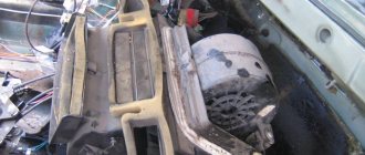
All connectors are disconnected from the control unit - We slightly lift the panel on the right side and fix it using improvised means.
The partially dismantled panel is pulled back and fixed - When access to the radiator is open, cover the floor under it with oilcloth, on which we install a container for collecting coolant.
To prevent coolant from spilling on the floor, you will need a shallow, wide container. - Using a Phillips screwdriver or a 7mm wrench, carefully unscrew the clamps securing the pipes;
The pipes should be removed gradually, allowing the coolant to flow into the container without pressure. - Drain the coolant from the pipes and radiator.
- Unscrew the radiator mounting screws.
The radiator is secured with four screws - We remove the old radiator.
- We install a new radiator.
- We put the pipes on the fittings and secure them with clamps.
- We assemble the panel in reverse order.
Video: replacing the VAZ 2113–15 heater radiator without dismantling the panel
https://youtube.com/watch?v=JYC8ijuYJdg
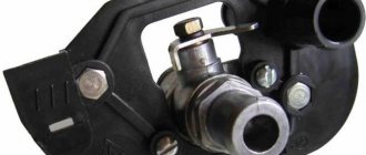
Replacing the heater tap
To replace the stove tap you will need:
- wrenches 10 (preferably socket) and 13;
- crosshead screwdriver;
- dry rags.
The algorithm of actions is as follows:
- We place the car on the inspection hole, unscrew the bolt plug and drain the coolant.
- In the cabin, unscrew the four screws securing the left panel cover.
- In the engine compartment we find pipes going from the engine to the tap. Use a screwdriver to loosen the clamps and remove the pipes.
The pipes are fixed with metal clamps - In the cabin, under the panel on the passenger seat side, we find the heater tap and the pipes coming from it. Use a Phillips screwdriver to loosen the clamps and remove the pipes, having previously laid rags under the tap in case of coolant leakage.
When removing the pipes, you need to cover the floor with dry rags - In the engine compartment, using a 10mm wrench, unscrew the two nuts on the studs connecting the valve body to the body.
To dismantle the tap, you need to unscrew two nuts with a 10mm wrench - We take the faucet out of the cabin and disconnect the drive cable from it.
Before dismantling the tap, you need to disconnect the drive cable from it. - We install a new faucet.
- We reassemble in reverse order.
The process of replacing the VAZ 2113–15 heater tap is described in more detail here.
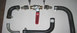
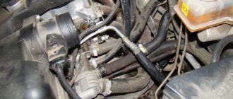
Replacing stove pipes
When replacing a heater radiator or heater tap, it is advisable to replace the pipes as well. To ensure access to them, you will need to perform the actions provided for in paragraphs 1–25 of the instructions for replacing the radiator. Then you need to loosen the clamps and remove the pipes from the stove tap from the passenger compartment. After this, the pipes going from the engine to the tap are disconnected from the engine compartment. All this is done using a Phillips screwdriver.
After installing new pipes, do not immediately tighten the clamps too much. First you need to assemble everything, add coolant, start and warm up the engine and check the connections for antifreeze leaks. When the rubber of the pipes warms up, the clamps can be tightened a little more.
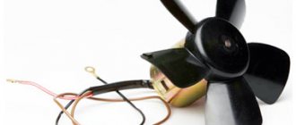
Replacing the heater resistor
If the stove fan can only operate in one mode, regardless of the switch position, you need to check the resistor. To do this you will need:
- Phillips screwdriver;
- fine-grained sandpaper;
- multimeter
The work order is as follows:
- Disconnect the negative terminal from the battery.
- Using a screwdriver, unscrew the screws securing the right cover of the center console.
To remove the cover you need to unscrew four screws - We find a resistor under the cover on the heater body, disconnect the connector from it and inspect the contacts. If there are traces of oxidation on them, remove them with sandpaper.
The resistor is installed on the heater housing - We connect the connector, the battery and check whether the fan is working in other modes. If not, disconnect the battery and use a screwdriver to unscrew the screw securing the resistor.
- We remove the resistor and use a multimeter to measure the resistance of the additional element and the entire device. It should be 0.2 and 0.8 ohms, respectively. If the resistance is greater or less, change the resistor and reassemble in the reverse order.
To determine the health of the resistor, you need to measure the resistance of its windings
Wiring diagram VAZ-2114 for old models
Electrical diagram of car 2114: 1 – headlight; 2 [Installed on a part of the car] – fog lamp; 3 – ambient temperature sensor; 4 – electric engine radiator fan; 5 – block for connection to the wiring harness of the engine control system; 6 – engine compartment lamp switch; 7 [Installed on a part of the car] – reserve block for connecting an audio signal with one terminal (the negative terminal is connected to the body); 8 – sound signal; 9 – liquid level sensor in the windshield washer reservoir; 10 [Installed on a part of the car] – brake pad wear sensor; 11 – low oil level sensor; 12 – generator; 13 [Installed on a part of the car] – engine compartment lamp; 14 – temperature indicator sensor; 15 – starter; 16 – battery; 17 [Installed on a part of the car] – relay for turning on fog lights; 18 – coolant level sensor in the expansion tank; 19 – sensor of insufficient brake fluid level; 20 – reverse light switch; 21 – windshield wiper gear motor; 22 – emergency oil pressure sensor; 23 – rear window washer electric pump; 24 – electric pump for windshield washer; 25 – instrument panel; 26 – mounting block of fuses and relays; 27 – brake signal switch; 28 – ignition relay; 29 - ignition switch (lock); 30 – glove box lighting lamp; 31 – switch for the glove compartment lighting lamp; 32 – rear window heating switch; 33 – rear fog light switch; 34 [Installed on a part of the car] – fog light switch; 35 – combined switch for side lights and headlights; 36 – alarm switch; 37 – steering column switches; 38 – brightness control for instrument lighting; 39 – illumination lamp for the headlight hydraulic adjustment control handle; 40 – socket for connecting a portable lamp; 41 – side direction indicator; 42 – interior lighting switch (front door open sensor); 43 – interior lamp; 44 – electric fan of the ventilation and heating system; 45 – additional resistor of the electric fan of the ventilation and heating system; 46 – switch for operating modes of the electric fan of the ventilation and heating system; 47 – illumination lamp for the handle of the operating mode switch of the electric fan of the ventilation and heating system; 48 – backlight lamp for the heater control unit; 49 – display unit of the on-board control system; 50 [Installed on part of the car] – trip computer; 51 – interior lighting switch (rear door open sensor); 52 [Installed on a part of the car] – block for connecting a clock; 53 – fuel module; 54 – ashtray illumination lamp; 55 – cigarette lighter; 56 – interior lamp; 57 – switch for the parking brake warning lamp; 58 – rear light; 59 – license plate light; 60 – additional brake light; 61 – heating element for heating the rear window; 62 – rear window wiper gear motor; A – pin numbers in the connecting blocks.
Diagnosis of heating system faults
Heating system malfunctions are accompanied by the following symptoms:
- the fan does not work;
- cold air enters the cabin;
- the damper does not work;
- there is a coolant leak;
- the stove begins to make uncharacteristic sounds (whistles, hums, gurgles);
- Steam or smoke appears from the heater ducts.
Why the stove does not work or does not heat the air
If the stove fails, it either does not work at all, or it works but does not heat the air. In the first case, first check the fan wiring, starting with fuse F7. If the fuse is blown, replace it. Then they check the relay, which may not turn on the first time or only when the engine is warm. In this case, the relay is replaced with a new one.
Then the serviceability of the electric motor is assessed. To do this, power is directly supplied to its contacts from the battery. If the electric motor starts to operate at maximum speed, then it is in good condition. Otherwise, it will need to be repaired or replaced.
The intensity of the air flow is adjusted using a resistor having two spirals with resistances of 0.82 Ohm and 0.23 Ohm. In the first mode, the current flows through both spirals, in the second - only through a spiral with a resistance of 0.23 Ohms, in the third - bypassing the spirals, that is, without resistance at all. If the resistor is faulty, the fan will only operate in the third mode at maximum speed (handle in the extreme right position). The problem is solved by replacing the resistor, which is located on the driver's side above the accelerator pedal.
If the resistor is faulty, the heater fan will only be able to operate at maximum speed.
If cold air enters the cabin, this may be due to:
- Airlock. It could have formed when replacing the coolant, when the system was depressurized, or because there was insufficient amount of coolant in the system. To remove the plug, remove the heater radiator pipe, use a watering can to add antifreeze to the maximum and put the hose back in place. After starting the engine, coolant under pressure will displace the remaining air from the system.
- Stove tap jammed. This happens if the tap was not initially opened all the way, and during operation, oxide and scale formed on the inner surface, preventing the normal circulation of the liquid. You can try to open the tap using pliers or immediately replace it with a new one.
- The stove radiator is clogged. When using low-quality coolant, the radiator honeycombs may become clogged. The problem is solved by flushing or replacing the heat exchanger. The feasibility of washing is determined by the scale of contamination.
- Installation of a low-quality radiator. In a defective product, the honeycomb may be incorrectly soldered. The radiator should be replaced.
- Low pressure in the cooling system. If heat transfer increases at higher speeds, the pump needs to be replaced.
- Low coolant level. It is necessary to check the level and add antifreeze if necessary.
- Damage to the heater fan impeller. The impeller is carefully inspected and replaced if mechanical damage is detected.
- Cabin filter dirty. If it is heavily polluted, the power of the electric motor will not be enough to pump warm air into the cabin. The filter is replaced with a new one.
- Damage to the cylinder head gasket. If the cylinder head gasket is blown, white smoke will come out of the exhaust pipe. The problem is solved by replacing the gasket and dismantling the cylinder head.
This is interesting: How is the performance of ABS and ESP tested in practice?
If the stove is clogged, warm air will stop flowing into the cabin.
Heater dampers don't work
The distribution of air flows throughout the cabin is carried out by dampers, which, in turn, are controlled using cables. When these cables fail, problems arise with directing the air flow to the windshield or to the foot area. In addition, the damper that blocks the flow of air from the street begins to work incorrectly. In this case, adjustment of the damper drives is required.
Such situations can arise even on a new car. Slightly warm air begins to flow from the lower, upper and side deflectors, and hot air begins to flow from the center console. This is due to the poor build quality. There are gaps between the joints of the air ducts and the dampers, which leads to warm air entering only from the center console and heating the panel from the inside.
The drive cable is always taut. Therefore, over time it bends, breaks off or stretches. In this case, it is necessary to adjust the damper drive, which is performed in the following order:
- In the stove, we look for a bracket with which the cable sheath is held on the heater body.
- A galvanized metal lever located on the left side is pulled back. This position corresponds to the maximum opening of the damper.
- The length of the cable is tightened and adjusted. The long lever on the lever block in the extreme right position should open the damper completely.
- After adjustment, the cable is securely fixed.
Video: adjusting the heater damper
Why is antifreeze leaking from the stove?
A coolant leak in the heating system can occur from:
- stove radiator;
- stove tap;
- stove pipes.
If a coolant leak occurs from the radiator, it is usually replaced with a new one. Repairs to restore tightness are usually complex and labor-intensive. In addition, if the radiator has been in use for a long time, its tubes become clogged with deposits and dirt, and, as a result, heat transfer decreases.
The valve opens and closes the coolant supply to the radiator, thereby regulating the heat in the cabin. Over time, it may begin to leak, as evidenced by the characteristic smell of antifreeze in the cabin, a puddle on the floor on the passenger side and a decrease in the coolant level in the expansion tank. The faucet cannot be repaired and in such cases is replaced entirely.
If the heater radiator starts to leak, it is usually replaced with a new one.
The cause of coolant leakage from the pipes is usually their wear - the rubber ages and cracks over time. When diagnosing a problem, you need to wipe the suspected leak areas with a rag and observe the outlet and inlet pipes on a warm engine. Worn hoses are always replaced with new ones.
The stove makes a hum, whistle, murmur
The cause of uncharacteristic sounds (whistle, hum, murmur, etc.) from the heater is usually a faulty electric motor. Lack of lubrication, contamination, wear of bearings and bushings - all this leads to the fact that the motor begins to whistle. It is removed, disassembled and cleaned, and the rubbing elements are lubricated. If the bearings are heavily worn, the motor will not make a whistle, but a hum. In such a situation, lubricant may not help, and the electric motor will need to be replaced.
Steam is coming from the stove
Sometimes steam starts coming out of the stove. The reason for this is a leak in the heater core. The leaking coolant hits the hot radiator housing and begins to quickly evaporate, and the smell of antifreeze appears in the cabin. To fix the problem, you will need to disassemble the stove and replace the heat exchanger.
Sometimes white steam comes from under the hood and enters the cabin. This happens when antifreeze gets on the hot manifold or exhaust system pants. In this case, you will need to find the location of the leak and fix it. The most common cause is damaged pipes.
This is interesting: Nissan Leaf in Europe will fall in price by 3 thousand euros
VAZ-2114 diagram (second option)
Electrical diagram of VAZ-2114 cars (without engine control system):
1 – headlights; 2 – fog lights; 3 – air temperature sensor; 4 – electric motor of the engine cooling system fan; 5 – blocks connected to the wiring harness of the ignition system; 6 – engine compartment lamp switch; 7 – block for connection to a single-wire type audio signal; 8 – sound signal; 9 – washer fluid level sensor; 10 – front brake pad wear sensor; 11 – oil level sensor; 12 – generator; 13 – engine compartment lamp; 14 – coolant temperature indicator sensor; 15 – starter; 16 – battery; 17 – relay for turning on fog lights; 18 – coolant level sensor; 19 – brake fluid level sensor; 20 – reverse light switch; 21 – windshield wiper gearmotor; 22 – oil pressure warning lamp sensor; 23 – block for connecting to the rear window washer electric motor; 24 – electric motor for windshield washer; 25 – instrument cluster; 26 – mounting block 2114; 27 – brake light switch; 28 – ignition relay; 29 – ignition switch; 30 – glove box lighting lamp; 31 – glove box lighting switch; 32 – rear window heating element switch; 33 – rear fog light switch; 34 – fog lamp switch; 35 – switch for external lighting lamps; 36 – alarm switch; 37 – steering column switches; 38 – switch for instrument lighting lamps; 39 – illumination lamp for the headlight hydrocorrector scale; 40 – plug socket for a portable lamp; 41 – side direction indicators; 42 – lamp switch on the front door pillars; 43 – canopy for individual interior lighting; 44 – heater fan electric motor; 45 – additional resistor of the heater electric motor; 46 – heater fan switch; 47 – heater switch illumination lamp; 48 – backlight lamp for heater levers; 49 – on-board control system unit; 50 – trip computer; 51 – lamp switch on the rear door pillars; 52 – block for connecting the wiring harness of the engine control system; 53 – electric fuel pump and gasoline quantity sensor; 54 – front ashtray illumination lamp; 55 – cigarette lighter 2114; 56 – trunk lighting lamp; 57 – trunk light switch; 58 – interior lamp; 59 – parking brake warning lamp switch; 60 – rear external lights; 61 – rear internal lights; 62 – block for connection to the rear window heating element; 63 – license plate lights; 64 – additional brake signal located in the spoiler.
Conventional numbering of plugs in blocks:
- A – headlight blocks;
- B – electric fuel pump block;
- C – blocks of the mounting block, ignition switch, windshield wiper gearmotor;
- D – blocks for the interior lighting.
Useful: VAZ tachometer connection diagram
Solving problems with a faulty stove, unit design
If a motorist wants to deal directly with the heater design, he should know what the VAZ-2114 stove diagram looks like. For active operation of the heater, only a few important parts are needed, in particular a ventilation engine, an additional resistance resistor and a toggle switch through which you can switch the speed of the unit.
Due to the fact that the motorist is faced with a system malfunction, he must first diagnose the performance of the heating device by setting the switch to the first position, then gradually move it to the second and third speed modes. Using the lever you can adjust the direction of the air flow, while the last position will help regulate the choice of air temperature.
Therefore, if the unit does not respond to the actions of the car owner, most likely the fan has stopped functioning properly. Apparently it just stopped turning on. However, if the heatsink still shows itself at least at some speeds, the problem may be related to the additional resistor. In such a situation, it would not be superfluous to check the VAZ-2114 stove, in which the switch may be inactive.
In the event that the car owner does not know how the heater on the VAZ-2114 works, and the heater fan operates at full power, while the temperature switch is set to maximum (the car’s power unit is also well warmed up), and only cold air flows from the heater, you will have to deal with the stove radiator, which, in all likelihood, is very clogged.
Wiring diagram VAZ-2114 new models
The updated engine has a new injection scheme, so it was necessary to use some new devices, as well as replace the ignition coil with a more efficient one and adapted to Euro 3 conditions. In order to comply with them, the engine had to minimize the amount of CO at start-up. And for this it was necessary to lean the mixture. Since a lean mixture ignites worse, it needed a more powerful spark to spark. This explains the use of a coil of increased power.
- block headlights;
- gearmotors for headlight cleaners*;
- fog lights*;
- ambient temperature sensor;
- sound signals;
- engine compartment light switch;
- engine cooling fan electric motor;
- generator VAZ-2114;
- low oil level indicator sensor;
- washer fluid level sensor;
- front brake pad wear sensor;
- wire ends connected to the common windshield washer pump**;
- windshield washer pump;
- headlight washer pump*;
- wire ends for connecting to the rear window washer pump on VAZ-2113 and VAZ-2114 cars;
- low oil pressure indicator sensor;
- engine compartment lamp;
- wire lug for connecting to the engine management system wiring harness;
- windshield wiper gear motor;
- starter VAZ-2114;
- block connected to the wiring harness of the ignition system on carburetor cars;
- coolant temperature indicator sensor;
- reverse light switch;
- low brake fluid level indicator sensor;
- accumulator battery;
- low coolant level indicator sensor;
- relay for turning on fog lights;
- mounting block;
- brake light switch;
- plug socket for a portable lamp;
- hydrocorrector scale illumination lamp;
- parking brake indicator lamp switch;
- block for connecting a backlight lamp;
- switch for instrument lighting lamps;
- Understeering's shifter;
- hazard switch;
- front seat heating element relay;
- ignition switch;
- rear fog lamp circuit fuse;
- front seat heating elements circuit fuse;
- door lock circuit fuse;
- front ashtray illumination lamp;
- ignition relay;
- cigarette lighter VAZ-2114;
- glove box lighting lamp;
- glove compartment light switch;
- heater fan motor;
- additional heater motor resistor;
- heater fan switch;
- heater switch illumination lamp;
- heater lever illumination lamp;
- gear motors for electric windows of the front doors;
- right front door ESP switch (located in the right door);
- gear motors for locking front door locks;
- wires for connecting to the right front speaker;
- gear motors for locking rear doors;
- wires for connecting to the right rear speaker;
- door lock control unit;
- wires for connecting to radio equipment;
- headlight wiper switch*;
- rear window heating element switch;
- rear fog light relay;
- block for connection to the heating element of the right front seat;
- rear fog light switch;
- right front seat heating element switch;
- fog light switch*;
- switch for external lighting lamps;
- left front seat heating element switch;
- block for connection to the heating element of the left front seat;
- wires for connecting to the left front speaker;
- left front door power window switch (located in the left door);
- right front door power window switch (located in the left door);
- wires for connecting to the left rear speaker;
- side direction indicators;
- dome light switches on the front door pillars;
- dome light switches on the rear door pillars;
- lampshade VAZ 2114;
- individual interior lighting lamp;
- block for connecting to the wiring harness of the electric fuel pump;
- trunk light switch;
- instrument cluster;
- trunk light;
- on-board control system display unit;
- trip computer*;
- block for connecting the wiring harness of the engine management system;
- rear exterior lights;
- rear interior lights;
- pads for connecting to the rear window heating element;
- license plate lights;
- additional brake signal located on the spoiler.
Numbering order of plugs in blocks:
A – headlight units and headlight cleaners; B – cigarette lighter; B – mounting block, instrument cluster, ignition switch, windshield wiper and other electrical components (for blocks with a different number of plugs, the numbering order is similar); G – relay for turning on the rear fog light; D – alarm switch; E – electric window motors and door lock motors; F – interior lamp.
In the instrument panel wiring harness, the second ends of the white wires are brought together into one point, which is connected to the instrument lighting switch (except for the white wire, from plug “4” of block “X2” of mounting block 28 to display block 83 of the on-board control system). The second ends of the black wires are also brought together to points connected to ground. The second ends of the yellow wires with a blue stripe are brought together to a point connected to plug “4” of the “X1” block of the mounting block. The second ends of the white wires with a red stripe are brought together to a point connected to plug “10” of the “X4” block of the mounting block. The second ends of the orange wires are brought together to a point connected to plug “3” of the “X4” block of the mounting block.
Explanations for the 8-pin injector block: white-red and blue - for the check light bulb, blue-red - ignition, gray - speed sensor, brown-red - tachometer, blue-white - driver's door switch (for the immobilizer), green- red - K-line (may not exist), green - fuel consumption. Next to it is a pink wire - to the fuel level sensor.
See the complete diagram in one file below (click to enlarge):
Basic aspects of tuning
Car tuning is not only about illuminating the dashboard with LEDs. Tuning the VAZ 2114 stove is required in situations where cold air blows from the sides of the stove, or the interior is heated unevenly.
To do this, you need to remove the side cover on the gas pedal side. The clamps holding the throttle cable should be loosened. Then you need to pull it back and tighten the clamp. Next, you should install the damper control levers. From this moment on, warm side air should blow, warming the driver and passengers in the cabin.
Heating system repair
At the second stage of tuning, it is necessary to ensure that air coming from outside passes through the heater. The operation of the damper and the tap is carried out by the operation of one engine. It should be ensured that it does not control the damper. To do this, the right cover of the torpedo is removed, and then the one located on the right is disconnected and pulled from the two temperature control cables from the engine. The damper should be in its maximum position. The cable should be tightened and the excess should be trimmed.
Relays and fuses VAZ 2114
F1 for 10 Amps (A) rear fog lights and rear fog light warning lamp. F2 for 10 A turn signal lamps, turn signal relay, hazard lights, hazard warning lights. F3 7.5 A lamps for interior lighting (both) and trunk, ignition lighting, powertrain control system control lamp, brake lamps, computer, if available. F4 20 A carrier, relay and rear window heating element. F5 20 A horn and its relay, cooling fan. F6 30 A power windows and their relays F7 30 A motor heater, headlight cleaner, windshield washer, cigarette lighter, glove compartment light bulb, rear window heating relay winding. F8 7.5 A right fog lamp. F9 7.5 A left fog lamp. F10 at 7.5 A left side marker, lamp signaling the inclusion of the side light, lamps for illuminating the sign, engine compartment, illumination of switches and instruments, instrument lighting switch. F11 at 7.5 A right side. F12 at 7.5 A right low beam. F13 at 7.5 A left low beam. F14 for 7.5 A left high beam and a light indicating that the high beam headlights are on. F15 at 7.5 A right far. F16 30 A - a light indicating insufficient oil pressure, brake fluid level, engagement of the parking brake, low battery, instrument cluster, relay for monitoring the health of lamps, indication of control systems, reversing lamps, turn indicators and their relays, as well as an alarm if turning mode is turned on, computer, generator excitation winding is turned on at the moment the engine starts.
Heater maintenance
To ensure that the VAZ-2114 heater heats well in winter, carry out maintenance of the heater before the cold weather:
- Remove it from the car.
- Disassemble and clean.
- Check the functionality of the dampers, seal their ends with sealants.
- Seal the joints with sealant.
- Flush the radiator.
- After assembly, adjust the drive cables so that when moving the sliders, the valves and the tap become in their extreme positions.
These measures are enough for the heating system to function normally in winter, providing warmth to the car interior.
Finally, we note that the reasons for the poor operation of the stove were discussed above, but it still continues to function. But this unit also has breakdowns and then the stove fails and stops working completely. Such reasons include breakdown of the radiator, leaks at the joints of the pipes, fan malfunction (open circuit, exhausted motor life or burnout).
VAZ-2114 wiring harness diagrams
Instrument panel harness
Glove compartment lighting harness
Front harness (without fog lights)
Rear harness VAZ-2114
Wiper Harness
Additional harness
Connects to the instrument panel, the connector is next to the hood handle. Pink - door lock, permanent plus, fuse hangs next to the hood release handle. White and black - on the door for electric windows, plus during ignition, switched on through a relay and fuse in the mounting block. Also in the photo is the wiring for the radio speakers.
Right door harness
Connects to an additional harness.
Left door harness
Connects to an additional harness.
Seat heating harness
The gray wire is connected to the connector where the additional harness is connected (to the gray wire if there is one), plus when igniting, the relay is attached next to the mounting block and the fuse is located next to the hood handle. The white wire is connected to the additional harness, button illumination.
Replacement instructions
The radiator is a replaceable unit, so if it is faulty, it needs to be replaced.
The replacement procedure consists of the following steps:
- First of all, you need to drain the coolant.
- Next you need to dismantle the dashboard. You can remove not the entire tidy, but only part of it to get to the radiator. How to remove the panel is described in the operating instructions.
- Before replacing, it is necessary to disconnect all wires and hoses that go to the radiator.
- Then you need to unscrew the fasteners and dismantle the unit.
- The removed radiator must be cleaned if it is clogged. If it leaks, it needs to be changed. Assembly should be carried out in the reverse order (video author - VChSLV).
After the repair, the microclimate in the cabin will be restored and no frost will be scary.