Print this article Font size 16
Today we will get acquainted with the stove and its structure on a VAZ 2110 car.
As you know, the heating system has a direct impact on the level of comfort. If in summer there is no special need for interior heating, then in autumn and winter it is problematic to imagine traveling without it. Theoretically, you can drive, but lower temperatures are unlikely to benefit your health.
Dismantling the heater
Introduction
It is impossible to independently repair your own car without knowledge regarding the structure of all components. The skill of reading any drawings is considered equally valuable. Such skills can only be acquired by having certain experience, which comes over the years in the process of operating and maintaining your car. In the article below we will look at the design of the VAZ-2110 heater.
It is no secret that a properly functioning heater device in the top ten of the domestic automobile industry allows the driver and passengers to feel as comfortable as possible while driving. The article discusses the connection diagram of the unit and provides a description of the elements that make up the stove. The information can be useful not only to novice amateur mechanics, but also to experienced craftsmen who have difficulties repairing the heater.
Repair
As we have already noted, the design of stoves on dozens with carburetor and injection engines has practically no differences. Therefore, the repair instructions below are suitable for owners of a VAZ 2110 with both types of power units.
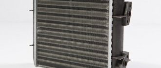
If you are planning to overhaul your old-style stove, we recommend starting with the purchase of a radiator. Use copper as it is more efficient and helps the heater work better.
To carry out repairs correctly, strictly follow the points presented in our instructions and rely on video materials.
- There is a plug on the engine block through which coolant is drained into any container. If you plan to use the same antifreeze or antifreeze again, choose clean containers.
- Next you need to move the frill forward. This process will take quite a long time, so be patient.
- Next, you need to remove the windshield wipers and get rid of as much as possible of everything that could interfere with the repair process.
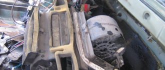
- Remove the body of your stove. It is divided into two parts, which is important to know in advance. The front part of the stove body is removed directly along with the fan.
- After this comes the stage of dismantling the cabin filter. Check its current status. If the filter is dirty, this is an excellent reason to replace it.
- The next stage involves removing the second part of the housing.
- Loosen the clamps used on the hoses a little. This will allow you to easily remove the hoses.
- Having applied some effort, you can now finally remove the radiator from its seat.
Heating device design
The heating of the VAZ-2110, through which a motorist can feel comfortable in his movable property at any time of the year, consists of several separate devices working in close conjunction. The central device of the unit is the radiator, with the help of which the air flows going into the cabin are heated. In order to be able to repair or replace the radiator, you will have to look for ways to it under the hood.
The second most important device is the air distributor, which has several pipes running throughout the cabin of the “tens”. Compared to the old-style models that preceded the release of the VAZ-2110, the new car has an evaporator, which has found a place in the air conditioning system.
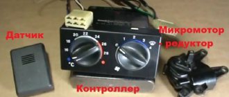
The operation of the stove is controlled through a special control unit. In the VAZ-2110 operating manual, this device has a different name (controller). The unit operates together with a temperature sensor located in the cabin. The sensor transmits information regarding temperature to the unit, after which the data is compared (the information displayed on the handle is taken into account). As soon as the system detects a temperature difference of 2°, warm or cooled air immediately begins to flow into the cabin.
To understand how the heater works, you need to pay attention to the handle of the device; two extreme positions deserve special attention - MAX and MIN. The fact is that when the handle is set to one of these indicators, the system begins to supply heat, not taking into account the data from the temperature sensor.
The VAZ-2110 stove provides for the presence of such a device as a gearmotor. The task of this device is to open and close the damper. A small-sized electric motor is extremely important in the operation of the heater. Even with a minor breakdown of the gearmotor, the system will be able to provide the car owner with only cold or only hot air. If this device breaks while the damper is closed, then the entire system will cease to perform its function. The main components of the heating device:
- radiator;
- a device that distributes air flows;
- SUAO block;
- ceiling sensor;
- lever;
- flap;
- gearmotor.
Purpose of the radiator
The VAZ-2110 stove of the new model has a radiator, through which the air flowing into the vehicle is heated. Quite often on the global network you can find diagrams in which the radiator is designated as a heat exchanger. The heating process in the device occurs due to the supply of warm antifreeze. The radiator is connected to the cooling system of the power unit through several pipes and hoses. Coolant circulates inside the heat exchanger all the time. The volume of incoming air and its direction depend on the location of the damper. When the heater damper is in an intermediate position, part of the air flows through the heat exchanger, and the remaining volume bypasses the radiator. In the diagram you can see that the radiator of the new model differs from other models in several useful modifications.
Operating principle of the control system and ceiling sensor
The operating principle of the VAZ-2110 stove can be understood by studying components such as the control system and the ceiling sensor.
The function of the ceiling sensor is to determine the temperature inside the vehicle. Then all the information will go to the SUAO block, where the incoming value will be equal to the temperature that is reflected on the handle of the VAZ-2110 heating device. As a result of the verification, the position of the damper will be changed or remain the same. Everything will depend on the difference between the values being compared. Through this simple manipulation, the temperature inside the car is controlled.
When setting the device to any of the extreme values, the information from the ceiling sensor will not be taken into account. The SUAO block is a set of microcircuits on which the functioning of the heater directly depends. If malfunctions occur, both the sensor and the control system can be replaced without much labor.
The device of the damper and gear motor
Due to the gearmotor, the position of the damper that regulates the air supply changes. This component of the system is controlled by the control system block. If a functioning device fails, the damper stops moving. The device itself looks like a small electric motor. Most often, a broken device must be completely replaced, since repairs are quite problematic. The same principle applies to the operation of the damper.
Differences in design
The VAZ 2110 was equipped with stoves of the so-called new or old model. Both systems, including those on the VAZ, which has an injector instead of a carburetor, are not particularly different in design.
So, the immediate differences:
- The main difference between the new stove and the old one is in the design of the heater radiator. Therefore, if you are repairing a heating system and decide to install a new model instead of an old radiator, then take into account some nuances;
- In addition, the SAUO controller is also not exactly like that. 4 or 5 position controllers manufactured before the fall of 2003 have already been discontinued and are not suitable for new heater models;
- The micro-gearboxes are also different, starting from release in September 2003. They differ in resistors (shaft position sensors), so you need to check whether the resistor in the MMR model that you purchased is interchangeable.
Old-style MMR
New sample MMR
Device diagram with all explanations
The operation diagram of the VAZ-2110 stove can tell the motorist about the presence of recirculation in it, in other words, moving air flows circulate inside the car without taking new volumes of air from the street. Thanks to this, dust and unpleasant odors, which are present in large quantities in the street air, do not enter the unit. However, it is worth noting the main drawback of such a system - the windows fog up too quickly. Experts recommend opening windows often (at a comfortable temperature outside). Otherwise, the stagnant air will negatively affect the health of everyone involved in driving this car. Due to the complexity of repair, the gearmotor must be completely replaced in case of malfunctions.
Heating and ventilation system
1 – electro-pneumatic valve 2 – front heater air intake housing 3 – air intake water deflector flap 4 – recirculation damper control valve 5 – air intake recirculation damper 6 – rear heater air intake housing 7 – heater duct damper 8 – heater control damper 9 – radiator 10 – heater radiator casing
11 – steam exhaust hose fitting 12 – supply hose fitting 13 – exhaust hose fitting 14 – heater electric motor with fan 15 – electric motor housing 16 – support platform for the heater control damper drive lever 17 – heater control damper drive lever 18 – damper drive micromotor 19 – resistor 20 – heater casing cover
Interior ventilation is supply and exhaust: air is supplied into the cabin through holes in the windshield trim (spontaneously - when the car is moving, or forced - when the heater fan is operating) and exits through the cracks between the upholstery and the inner door panels and then through the holes in the ends of the doors. These holes have valves that allow air to come out, but prevent it from getting inside the car. This design improves the thermal insulation of the cabin.
The air entering the cabin is heated, if necessary, by passing through the heater radiator and distributed in accordance with the position of the air flow control handle. The main part of the air is directed to the windshield and - through deflectors blocked by flaps - to the side windows and to the central part of the cabin. Air is also supplied to the feet of the driver and the passenger sitting in front through two pairs of deflectors (one pair at knee level, the other at the floor) and to the feet of rear passengers through the lining on the floor tunnel and two air ducts under the front seats.
To speed up the heating of the cabin and prevent the entry of outside air into the cabin (when crossing gas-filled, smoky, dusty sections of the road), an air recirculation system is used. When the recirculation button is pressed down (on the instrument panel), the electro-pneumatic valve opens, and under the influence of vacuum in the intake manifold, the recirculation system flap blocks the access of outside air to the car interior. Thus, the recirculation system can only operate when the engine is running. At the same time, if the fan is turned on, the air in the cabin continues to circulate, passing through the heater air ducts.
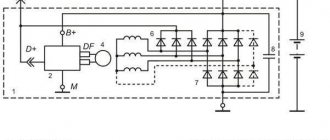
The fan has three operating modes: low speed, medium and automatic speed selection (determined by the control unit). The fan electric motor is a commutator, DC, with excitation from permanent magnets. Current consumption at maximum speed is 14 A. Depending on the selected speed, the electric motor is connected to the vehicle’s on-board network directly (maximum speed) or through an additional resistor. The latter has two spirals with a resistance of 0.23 Ohm and 0.82 Ohm. If both spirals are included in the circuit, the fan rotates at low speed, if only one (0.23 Ohm) rotates at medium speed.
Priora heater control unit pinout
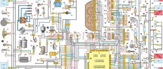
| Colored electrical diagrams VAZ 2170-71-72 LADA Priora |
Engine Control DiagramCar Front Wiring Harness ConnectionDashboard Harness ConnectionCar Rear Wiring Harness Connection
Colored electrical diagrams VAZ 2170 LADA Priora
Electronic engine control diagram Connection diagrams for the wiring harness of the front, rear of the car doors, trunk lid
| Instrument panel harness wiring diagram |
List of elements of the electrical connection diagram of the instrument panel harness of the LADA 2170 car
1, 2, 3 - instrument panel harness connectors to the front harness; 4 – instrument panel harness connector to the rear harness; 5 – contacts of the mounting block connector; 6 – brake light switch; 7 – instrument cluster; 8 – lighting control module; 9 – driver airbag module; 10 – horn switch; 11 – diagnostic block; 12 – on-board computer mode switch; 18 – ignition switch; 14, 15 – blocks to the electric power steering control unit; 16 – electrical package controller; 17 – light switch alarm;18 – windshield wiper switch;19 – air flow distribution gearmotor;20 – heater control unit;21 – heater electric motor switch;22 – rear window heating switch;23 – clock;24, 25 – instrument panel harness connectors to the radio;26 – hazard warning switch; 27 – glove compartment lighting switch; 28 – glove compartment lighting switch; 29 – instrument panel harness connector to the ignition system harness; 30 – airbag system control unit. Al, A2, AZ – instrument panel harness grounding points. B – mounting block block.
Instrument panel harness – 2170-3724030.
Ignition system harness wiring diagram
List of elements of the electrical connection diagram of the ignition system harness of the LADA 2170 car
1 – controller;2 – ignition system harness connector to the instrument panel harness;3 – main fuse box;4 * speed sensor;5 – rough road sensor;6 – oil pressure warning lamp sensor;7 – throttle position sensor;8 – sensor coolant temperature;9 – coolant temperature indicator sensor;10 – mass air flow sensor;11 – idle speed control;12 – electric fuel pump relay;13 – electric fuel pump power circuit fuse (15 A);14 – ignition relay;15 – relay fuse ignition (15 A); 16 – controller power supply fuse (7.5 A); 17 – crankshaft position sensor; 18 – oxygen sensor; 19 phase sensor; 20 – knock sensor; 21 – canister purge solenoid valve; 22 – sensor oxygen diagnostic;23 – ignition coil;24 – spark plugs;25 – injectors;26 – ignition coil wiring harness block to the ignition system harness;27 – ignition system harness block to the ignition coil wiring harness;28 – ignition system harness block to the injector harness ;29 – injector harness block to the ignition system harness. A – to the plus terminal of the battery; Bl, B2 – grounding points of the ignition system harness. C1 – grounding point of the ignition coil wiring harness. Ignition system wiring harness – 2170-37240*26 .Ignition coil wiring harness – 1118-3724148. Injector wiring harness – 11186-3724036.
List of elements of the electrical connection diagram of the front vehicle harness LADA 2170
1 – starter; 2 – battery; 3 – generator; 4 * battery and starter harness connectors and front harness; 5-7 front harness connectors to the instrument panel harness; 8 – engine compartment lamp switch; 9 – left headlight; 10 – right headlight ;11 - brake fluid level sensor;12 – air temperature sensor;13 – washer motor;14 – reverse light switch;15 – engine electric fan;16 – heater damper gearmotor;17 – additional resistor;18 – windshield wiper motor;19 – main fuse block; 20 – heater electric motor; 21, 22 – sound signal Al, A2, Bl, B2 – grounding points of the front harness. Front wiring harness – 2170-3724010. Battery wiring harness with housing – 2170-3724080. Battery connecting wiring harness and starter - 2170-3724070.
The main reasons for poor operation of an electric furnace
Before you can directly begin to find a solution to a problem, you need to be able to identify it quickly and effectively. First, it is advisable to consider the general structure of the furnace. So, the heater furnace consists of the following components:
- mounting block fuse;
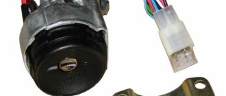
- incendiary lock;
- ignition switch together with its unloading relay;
- a special switch that regulates the operating mode of the furnace electric motor;
- additionally built-in resistor;
- stove motor;
- heated rear window of the car, which contains a heater adjustment button with a light indicator;
- a special functional element for heating glass.
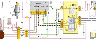
VAZ 2110 stove wiring diagram
One of the reasons for the malfunction of the electronic circuit of the furnace may be the lack of functional activity of the heater electric motor at both low and high speeds. In this situation, you must proceed as follows:
- First you should make sure that the fuse has not accidentally blown;
- If a blown fuse is detected, it will urgently need to be replaced with a new one.
Note. Before proceeding directly to replacing the old fuse with a new one, it is necessary to first and without fail establish the cause of the burnout. If this is not done, the service life of the new fuse will most likely be short.
- There may also be a break or damage to the wiring at the point of its connection;
- to eliminate the above reason, it is necessary to check the electrical circuit according to the furnace diagram;
- after which, it is necessary to eliminate the impulse, if it took place;
- if the heating switch does not function, then the most likely cause is a stuck pusher or burnt contacts;
- to accurately diagnose a switch malfunction, you need to check the voltage level at the side terminals while changing the position of the switch in space (to do this, it is enough to apply current to the main terminal);
- if during diagnostics a change in voltage is not detected when changing the position of the switch knob, then it must be urgently replaced;
- there are a huge number of possible reasons for the electric motor to fail to operate: broken electrical connections or armature winding, immobilized cleaning brush, oxidation and/or contamination of the armature commutator;
VAZ 2110 stove diagram and functional features
As you know, the main functional purpose of a car heater is to supply warm or cold air inside the cabin. In order to have a practical opportunity not only to identify a malfunction, but also to eliminate it, you need to know how the VAZ 2110 stove circuit is designed. After all, there are different types of possible malfunctions and there can be both problems in the electrical circuit and in one of the elements of the stove itself. For a VAZ 2110, the heater diagram and knowledge of it will make it easier for the motorist to find a break and repair the heater.
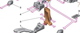
Do-it-yourself radiator cleaning
There are situations when you notice that the engine begins to overheat. In this case, it is necessary to check how the car’s engine cooling system works. The main “blow” from dust, dirt, poplar fluff, and leaves is taken by the radiator. As a result, it overheats and fails. Therefore, let's try to figure out how and, most importantly, with what, to clean it.
The concept of “cleaning” a radiator can be considered mainly from the following two positions: in the first case, if it needs to be cleaned from the outside, that is, its surface needs to be washed. The second option is to wash the insides of this device. The presented methods will allow you to achieve some positive results, but they require completely different amounts of effort and time.
In the photo you can see a radiator that is contaminated with poplar fluff. Next, we’ll look at how best to clean it from dirt (before work, be sure to make sure it’s cooled down).
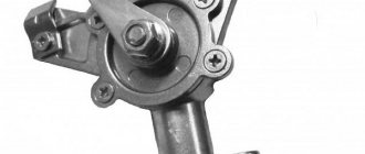
Instructions for replacing the heater valve VAZ 2114-2115
- Place the vehicle on the inspection hole. Drain the coolant into a prepared container. You can read about how to do this and where to find the drain plug in this article.
- Loosen the clamps of the pipes that go from the engine to the heater tap. Clean the threaded connections of the studs securing the heater valve. To do this, you can use a metal brush and penetrating liquid.
- Remove the pipes one by one. In this case, coolant leaks are possible; it is better to prepare the container.
- In the cabin, dismantle the side trim of the torpedo and pipes (if necessary). If they are not planned to be replaced, there is no need to unscrew them. Use a rag to remove any remaining antifreeze.
- Using a 10mm socket wrench, unscrew the nuts that secure the heater valve.
- Inside the cabin, pull the tap towards you, remove the spring clamp, and disconnect the control cable from the tap.
- After this, you can install a new stove tap. Before screwing it on, you need to connect the cable.
Reassemble in reverse order. Between the body and the tap you need to install new gaskets and seals, add sealant when connecting the pipes. Before pouring antifreeze into the cooling system, you must tighten the drain plug.