Tightening torque of cylinder head bolts
This indicator is directly dependent on the make of the car; on old-style domestically produced cars there are only two of them, on more modern versions of the car there are already 4. If you decide to tighten the cylinder head bolts yourself, then you will need either a warm, comfortable room or good weather for this. at least 20 degrees Celsius.
When carrying out repair work, you should thoroughly clean the bolts and connections from excess oil and dirt; this is especially important to do this if the gasket has leaked in the structure. In order to avoid deformation and overheating of the metal case, you should wait at least 20 minutes after each puff for the metal to return to its original shape. Before tightening the cylinder head bolts yourself, it would be a good idea to look up the tightening torque on the cylinder head of your car in a reference book or find out all the information from a competent auto mechanic.
IMPORTANT: To avoid mistakes, be sure to check the year of manufacture and model of your car.
In order not to redo the work, you should initially follow the correct order of tightening the cylinder head bolts.
Let's start to disassemble
First, drain the oil and antifreeze. We remove the protective cover, the air filter with pipes, disconnect the ignition coil connectors, the throttle cable and the throttle assembly.
We remove the thermostat housing and simultaneously disconnect all the available connectors and pipes. We remove all the wiring that was in our way towards the battery.
We remove the generator. We unscrew the eight thirteen nuts holding the intake manifold and remove it. We unscrew all the bolts securing the valve cover, as well as the side engine support.
Unscrew the eight nuts and remove the exhaust manifold.
Remove the timing belt, camshaft pulleys and pump.
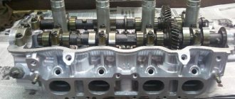
In three passes, so as not to deform the part, we first loosen and then unscrew twenty bolts of the camshaft bearing housing, the head is eight. Be sure to follow the sequence shown in the photo.
Remove the bearing housing. We remove the camshafts; there is a distinctive lip on the intake camshaft.
Also, in several passes, we first loosen and then unscrew the ten cylinder head mounting bolts. Be sure to follow the sequence shown in the photo.
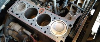
Remove the cylinder head. All sixteen valves are replaced.
Bolt torque
You can easily determine this indicator yourself without resorting to the services of specialists in the table, but you should keep in mind that for this you need to know exactly what information is contained on the marking, which is located on the top of the bolt. The marking located on the bolt head must contain the following information:
The mark of the factory that produced the product. Information about the strength class of the product. The thread on the right side does not contain markings, but the thread on the left side contains markings, which are located clockwise. Carbon steel bolts are marked with a strength class, which is indicated by two numbers separated by a dot. For example: 12.8,10.5,8.7 The first digit of the marking informs about 0.01 nominal value of tensile strength. This value is measured in MPa. If the value class is 8.7, then the first number 8 means 8 * 100 = 800 MPa or 800 N/mm2 or 80 kgf/mm2 The second indicator on the marking informs about the ratio of tensile strength to yield strength, this value is multiplied by ten. That is, with marking 8.7 it turns out 8*7*10=560 N/mm2
ATTENTION: The yield strength, in turn, has quite an important practical significance.
This indicator is the maximum possible load of the bolt used.
Stainless steel products are marked with the appropriate steel marking, that is, A2 or A4 and the corresponding tensile strength equal to 50, 60, etc. For example: A2-60 or A4-70. In a special table you can find out the practical tightening torques for the corresponding bolts made of carbon steel N/m. It should be taken into account that the bolt still has a margin of safety so that, as they say, it does not “drip”. However, this does not mean that all connections should be tightened to the maximum. Most often, such force leads to the connection becoming unusable, that is, there is a high probability of pushing through, damage to the elastic gasket, etc. It turns out that the values given in the tables are acceptable, but the load level in this case is approximately 60-70% of the yield strength.
Tightening torques for threaded connections
From the table you can find out what torques are required for tightening both bolts and nuts.
IMPORTANT: Never exceed these values.
| Thread (M) | Bolt strength Nm |
| 6 | 10 |
| 8 | 25 |
| 10 | 50 |
| 12 | 85 |
| 14 | 130 |
| 16 | 200 |
| 18 | 280 |
| 20 | 400 |
| 22 | 530 |
| 24 | 670 |
| 27 | 1000 |
| 30 | 1330 |
| 33 | 1780 |
| 32 | 2000 |
| 36 | 2300 |
| 39 | 3000 |
| 42 | 3700 |
The values listed in the table correspond to standard nuts and bolts that have metric threads. If non-standard or special fasteners are used, you should refer to the repair manuals for this equipment.
Tightening torque for main and connecting rod bearings
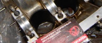
Before installing the liners, you must first remove the preservative grease from them and apply a small layer of oil to them. After this, the main bearings are installed. They are installed in the bed of the molar necks, do not forget that the middle liner is different from the others.
Next comes the installation and tightening of the bed covers. In this case, the tightening torque must be applied in accordance with the standards. The standards are most often specified in the vehicle operating rules. However, it happens that in operation there is not a word about these standards, in which case you should look for relevant information on repair work with a specific engine. For example, for Lada Priora cars, the tightening torque will be from 64 to 81 N/m.
Then you should begin installing the so-called connecting rod bearings. Do not forget to pay attention to the correct installation of the covers. Each cap is marked, so pay attention to this and do not mix up the caps.
IMPORTANT: The tightening torque for these caps is much less than for the main caps.
For example: If we take the same Lada Priora model, then the tightening torque value of the connecting rod bearings in this case will start from 43 to 53 N/m.
Please note that the data that we indicated for the example is correct only if new liners are used for repairs; for used parts these indicators will be different. If used inserts are used, then you should start from the maximum value specified in the documentation. This is done because the parts in this case may have wear. Ignoring this fact can lead to significant deviations from the norm.
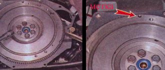
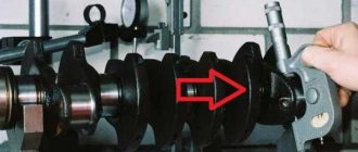
After tightening all the bolts, it will be advisable to rotate the shaft. There is a special wrench on the side of the crankshaft for tightening the nuts; you should calmly turn it clockwise. If there is some kind of malfunction or, for example, a ring has burst, then you will see it. After you check everything and make sure that there are no problems, you should once again check all the bolts using a special wrench for the tightening torque. Do not forget that the density with which the plain bearings will adhere directly to the crankshaft directly depends on how correctly this entire process is carried out, and this directly affects the operation of the car’s engine. If the bolts are not fully tightened, the entire lubrication cycle may be disrupted, which in turn may lead to breakage of the liner. If the bolts are overtightened, there may not be enough lubrication due to overheating of the liner.
IMPORTANT: If the bolt is not tightened correctly, the liner may even turn or melt, and this may lead to the fact that the engine will need to be completely repaired.
What are plain bearings
To better understand why engine bearings need to be tightened to a certain torque, let's take a look at the functions and purpose of these elements. Let's start with the fact that these sliding bearings interact with one of the most important parts of any internal combustion engine - the crankshaft. In short, the reciprocating motion of the piston in the cylinder is converted into rotational motion precisely thanks to the connecting rods and crankshaft. As a result, torque appears, which is ultimately transmitted to the wheels of the car.
The crankshaft rotates constantly, has a complex shape, experiences significant loads and is an expensive part. To maximize the service life of the element, connecting rod and main bearings are used in the crankshaft design. Taking into account the fact that the crankshaft rotates, as well as a number of other features, conditions are created for this part that minimize wear.
For the manufacture of liners, softer materials are used compared to those from which the crankshaft itself is made. The liners are also additionally coated with an anti-friction layer. Lubricant (motor oil) is supplied under pressure to the place where the liner is connected to the crankshaft journal. The specified pressure is provided by the oil pump of the engine lubrication system. In this case, it is especially important that there is the required clearance between the crankshaft journal and the plain bearing. The quality of lubrication of the rubbing pair, as well as the engine oil pressure in the engine lubrication system, will depend on the size of the gap. If the gap is increased, then the lubricant pressure decreases. As a result, rapid wear of the crankshaft journals occurs, and other loaded components in the internal combustion engine also suffer. In parallel with this, a knock appears in the engine.
We add that a low oil pressure indicator (in the absence of other reasons) is a sign that the crankshaft needs to be ground, and the engine liners themselves need to be changed taking into account the repair size. For repair liners, an increase in thickness of 0.25 mm is provided. As a rule, there are 4 repair sizes. This means that the diameter of the repair liner in the last size will be 1 mm higher. less compared to standard.
The plain bearings themselves consist of two halves, in which special locks are made for proper installation. The main task is to create a gap between the shaft journal and the liner, which is recommended by the engine manufacturer.
As a rule, a micrometer is used to measure the journal; the inner diameter of the connecting rod bearings is measured with a bore gauge after assembly on the connecting rod. You can also use control strips of paper for measurements, use copper foil or control plastic wire. The gap at the minimum mark for rubbing pairs should be 0.025 mm. An increase in the gap to 0.08 mm is a reason to bore the crankshaft to the next repair size
Note that in some cases the liners are simply replaced with new ones without boring the crankshaft journals. In other words, it is possible to get by only by replacing the liners and obtaining the desired gap without grinding. Please note that experienced specialists do not recommend this type of repair. The fact is that the service life of the parts at the mating point is greatly reduced, even taking into account that the gap in the rubbing pair corresponds to the norm. The reason is considered to be microdefects that still remain on the surface of the shaft journal if grinding is not performed.
Spark plug torque
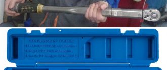
To repair and install spark plugs, a special tool is used, which is called a torque wrench, and this should not be forgotten. You also need to understand that not only the diameters of the threads in the engine housing itself differ, but also the tightening torque for each car manufacturer is different. Therefore, experts talk about the importance of understanding the “torque” of the spark plug being installed. Everything depends not only on the structure of the thread itself, but also on the force with which installation is carried out. If you need to mount a candle, but there is no specialized tool at hand, then installation using improvised tools is allowed. In order to understand with what force the candle should be tightened, you first need to become familiar with it. Most often, manufacturers leave information of this nature on the packaging or in the product manual. In addition to a detailed diagram, as well as the correct installation sequence, such instructions most often include information about the thread of a given candle. Before you begin installing candles, a number of necessary conditions must be met. The first rule that must be followed is to carry out installation only when the engine is cold. You should also thoroughly clean the threads from carbon deposits.
IMPORTANT: There is an opinion that the threads of a new spark plug should be pre-lubricated. However, this is not true and such actions may result in leaky tightening.
Initially, the candle should be screwed in by hand, but you should not be too fanatical in this matter and screw it in all the way. After you have secured the spark plug, you should tighten it with a spark plug wrench a few turns. The number of revolutions in this case depends on the type of gasket used, as well as the size of the thread. For example, for a standard type of spark plug with an M14 thread, 180 degrees, that is, 20 Nm, will be sufficient. Information about the thread size can be found on the packaging or on the candle body itself (sometimes engraving is done on the insulator).
IMPORTANT: Correct installation of the spark plug is important, since the durability of the car engine depends on it.
You should not screw the part all the way in, as in this case you can damage the already fragile threads not only on the spark plug itself, but there is also a high probability of damaging the groove in the engine, which is fraught with more serious consequences. In order to install a candle you do not need a lot of experience or knowledge of technical literature. The most important thing in this matter is to be careful, and it is also a good idea to familiarize yourself with the information provided by manufacturers.
Engine assembly
We wipe the crankshaft journals, cylinder bores and connecting rod bearing seats with a clean rag; by the way, they can also be degreased. We put new liners into the connecting rod and the cover, so that the antennae of the liners fit into the grooves.
Lubricate the bearings, crankshaft journals and cylinders with clean oil. We unfold the piston rings with locks as shown in the figure, the angle between them should be 120 degrees.
We put a mandrel on the piston to compress the rings, having previously lubricated it inside with clean oil. Not forgetting about the direction, the arrow on the piston should be directed towards the front of the engine, we place it in its cylinder.
We turn the crankshaft so that the connecting rod journal is at the very bottom. Gently tapping the wooden handle of a hammer pushes the piston into the cylinder. We remove the mandrel and push the piston down until the connecting rod sits on the crankshaft. We put the connecting rod bearing cap on the bottom, remembering the marks. Tighten the connecting rod cover mounting bolts to a torque of 5 kgf*m. We also repeat with all the other cylinders.
We put back everything that we removed from below. We blow through the top and clean the holes for the cylinder head mounting bolts. We install a new cylinder head gasket and the head itself. Lubricate the bolts with a thin layer of oil, most importantly without fanaticism. We tighten the bolts in several passes in the reverse order of unscrewing, see photo at the beginning of the article. The tightening sequence is as follows:
- first tighten everything with a torque of 2 kgf*m
- then we tighten everything to a torque of 7 – 8 kgf*m
- turn it 90 degrees
- turn it 90 degrees again
We install hydraulic compensators, camshafts and camshaft bearing caps. Lubricate all rubbing surfaces with clean oil. Before installing the camshaft bearing caps, lubricate the perimeter and rims around the spark plug wells with a thin layer of sealant. We tighten the bearing cover bolts in the reverse order of unwinding, with a torque of 2 kgf*m, see photo at the beginning. Well, then we install all the parts in the reverse order of removal. We fill in all the fluids and start it, it may not start right away, this is normal. When you first start it will smoke well until the oil on the cylinders burns, make sure the oil pressure light goes out. Let it run for a minute and turn it off, and suddenly see where something is leaking. We start it several more times, constantly increasing the operating interval, bring it to operating temperature, constantly checking the oil and antifreeze, and also pay attention to the fact that no extraneous noise appears. Let it rest for an hour and then idle again for about an hour, constantly monitoring the temperature. Well, then the break-in, if you sharpened it, if not, then you can drive only the first thousand kilometers, try not to raise the speed above 3000, and not tow it.
Cylinder head tightening torque
This parameter is always standard and does not depend on the engine type. Any head is tightened using two rows of screws. The screws are located parallel to the combustion chambers. The order of the holes in this case is from the first to the last cylinder.
The correct order for tightening the screws is as follows:
- Two bolted connections located in the center of the right and left rows. For example, in four-cylinder engines they are located between the second and third cylinders
- Next are two screw connections, which are located to the left of the central ones (one in each row)
- Two located on the right side of the central ones (similarly, one in each row)
- Two bolted connections that are located on the left side in both rows
- Two bolted connections in each of the two rows, but located on the right
The tightening torque is no more than 1 kgf.m.
Removing and installing connecting rods on the Priora engine
The interesting thing is that, although this part is located almost in the middle of the engine, it can be removed without removing the engine from the car. Yes, this is, of course, not an easy operation, but it is quite doable. It must be carried out either in an inspection hole or on a special lift for cars so that there is access to the oil pan. When the vehicle is positioned for surgery, the engine compartment protection underneath is removed first. The cylinder head, engine sump and flywheel are dismantled. It is advisable to remove the oil intake so as not to damage it. You can start removing the connecting rods.
It is worth starting from the first cylinder. This is in order to put the details in order and not get confused. Rotate the Priora crankshaft so that the lower part of the connecting rod is level in the lower position. Unlock and unscrew the bolts securing the liner cover. Remove it and set it aside along with the liner itself. After this, push the piston up and remove it from the cylinder. One by one, remove all the Priora pistons and connecting rods in this manner. Now you can repair or replace elements.
Table of tightening torques for threaded connections
| Bolt nut | Thread (M) | Strength class (Nm) 8.8 | Strength class (Nm) 10.9 | Strength class (Nm) 12.9 |
| 22 | 14 | 138 | 194 | 235 |
| 24 | 16 | 211 | 299 | 358 |
| 27 | 18 | 289 | 412 | 490 |
| 30 | 20 | 412 | 579 | 696 |
| 32 | 22 | 559 | 785 | 941 |
| 36 | 24 | 711 | 1000 | 1196 |
| 41 | 27 | 1049 | 1481 | 1775 |
| 46 | 30 | 1422 | 2010 | 2403 |
| 50 | 33 | 1932 | 2716 | 3266 |
| 55 | 36 | 2481 | 3491 | 4197 |
| 60 | 39 | 3226 | 4531 | 5443 |
| 65 | 42 | 3991 | 5609 | 6727 |
| 70 | 45 | 4992 | 7012 | 8414 |
| 75 | 48 | 6021 | 8473 | 10150 |
| 80 | 52 | 7047 | 10885 | 13092 |
| 85 | 56 | 9650 | 13582 | 16279 |
| 90 | 60 | 11964 | 16867 | 20202 |
| 95 | 64 | 14416 | 20300 | 24320 |
| 100 | 68 | 17615 | 24771 | 29725 |
| 105 | 72 | 21081 | 29645 | 35575 |
| 110 | 76 | 24973 | 35118 | 42141 |
| 115 | 80 | 29314 | 41222 | 49467 |
Tightening torque of connecting rod bolts
It makes absolutely no difference which tightening method you chose, as well as whether an old or new bolt will be used, the first thing you need to do is fix the free length for each of the bolts used. Be sure to record where each bolt was installed (i.e. in cylinder 1, 2, etc.). After the measurements have been taken, comparison should be made with the length of the new bolts. If the bolt has a stretch of more than 0.012 mm, it should be replaced, since in this case it has already lost its elastic properties. Bolt measurements should be made using an accurate measuring device. When assembling the connecting rod, the bolt head and the base of the thread will need to be lubricated with machine oil or the lubricant specified by the manufacturer in the instructions (the recommended tightening torque may vary for different models).
crank mechanism
This main engine unit consists mainly of the following groups:
Each part of the group has several additional elements. For example, each piston carries a set of O-rings, a connecting pin and pin retaining clips. The crankshaft has bearings and oil seals. The most interesting thing is the structure of the connecting rods.
The principle of operation of the mechanism
VAZ engines, like other cars, are based on explosive combustion of fuel. The piston creates a certain compression of the air-gasoline mixture, a spark from the spark generator ignites it, pushing the piston down, and the crank mechanism (CPM) converts translational motion into rotational motion. This occurs due to the special shape of the crankshaft. The mounting points of the connecting rods are located so that while the connecting rods pushing the pistons rise, the connecting rods pushed by the piston are lowered. And this process takes place in shifts.
Set of connecting rods "Priors"
These parts are collapsible. The main part is made of high quality metal. Only in the upper ring, where the piston locking pin fits, is an insert made of a different metal installed. In general, the connecting rod consists of the following parts:
- connecting rod;
- liner covers;
- coupling bolts 2 pcs.;
- special washers;
- connecting rod bearing.
This is due to the fact that the liners have special grooves for the passage of engine oil. Due to the high rotation speed, this unit requires uniform and abundant lubrication. The slightest discrepancy between these grooves and the oil supply holes of the crankshaft will lead to a disruption in the flow of lubricant and, as a result, jamming of the engine.
Pneumatic impact wrench with adjustable torque
Before we begin to analyze the main design features of a pneumatic impact wrench, it should be noted that this equipment is divided into two types:
- Unstressed
- Shock
Today, due to technical modifications, it is customary to divide this equipment into many models. However, with all this, the design of this tool is quite simple and is almost no different, regardless of the model. The main components are:
- Impact system, it may contain a jaw clutch, a cam, a pusher, spring and roller mechanisms, a flywheel with a roller and pins
- A pneumatic type engine, it is most often a rotary six-blade and is installed in the housing
- The reverse unit is located together with the trigger mechanism in the tool handle
- The starting part, which is also located in the handle
Many modern models are also additionally equipped with a handle, which is placed in two or more different positions relative to the body part. This addition allows you to ensure comfort when using the tool.
Afterword
Before reassembling the unit, it is necessary to check the condition of all the bolts. If there is the slightest discrepancy, it will be necessary to replace it. It is important to understand that otherwise a good result will be unattainable.
Also, you should not put off replacing the gasket, since such a minor problem will later result in the need to repair the entire power plant. In severe cases, the entire engine may need to be replaced. We also suggest watching the video tutorial: