Axel-roman › blog › tightening moments. Chevrolet Niva.
Tightening torque table for Chevrolet Niva 2123. If you don’t have the book, you can look it up here.
Tightening torques for the cylinder head, engine, gearbox, transfer case, axles and brake system. Why is a wide range of tightening torque needed? Because all dynamo keys have an error. It is better to take the moment in the middle of the range. Minimum permissible - maximum tightening torque. For example: 100-110 Nm.
Reminder:
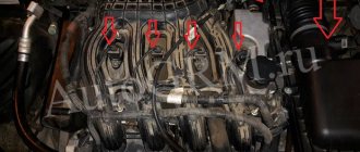
In places where there are many tightening points, for example, the intake manifold. It is better to go through the final moment several times. The dots in the middle “sag.”
List of tightening torques (table):
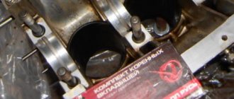
— Cylinder head bolt (cylinder head). M12×1.25.
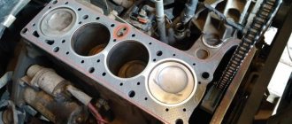
Clean the threaded holes from oil. Degrease the surfaces. If the length of the bolt shaft exceeds 117 mm, then it should be replaced with a new one. A non-shrinkable metal-reinforced gasket is installed between the block and the head. Reuse of the gasket is not permitted.
To ensure a reliable seal and avoid tightening the bolts during vehicle maintenance, we tighten them in four steps:
1st step - tighten bolts 1–10 to a torque of 20 Nm; 2nd step - tighten bolts 1–10 to a torque of 70–86 Nm, and bolt 11 to a torque of 31–39 Nm. 3rd step - then turn bolts 1–10 by 90°; 4th move - and another 90°;
It is advisable to use a rotation scale.
— Hydraulic support of the valve lever. (Hydraulic compensator) М24×1.5 15–20 Nm — Camshaft sprocket mounting bolt. M10×1.25. 41–51 Nm — Nut securing the camshaft bearing housing. M8. 18–23 Nm
Apply a thin layer of engine oil to the camshaft cams and journals, bearing housing beds and working surfaces of the valve drive levers. When installing the bearing housing, make sure that the installation sleeves (on the outer mounting studs of the cylinder head on the left side) fit into the housing housings without distortion.
— Bolt securing the main bearing cover. M10×1.25. 68–84 Nm — Oil pump mounting bolt. M8. 22–27 Nm - Oil pan mounting bolt. M6. 5–8 Nm — Oil separator cover stud. M8. 13–21 Nm — Oil separator cover mounting nut. M8. 13–21 Nm - Cylinder head bolt. M8.
— Nut securing the cylinder head cover. M6. 2–5 Nm — Oil pump drive shaft sprocket bolt. M10×1.25. 41–51 N·m — Coolant pump (pump) mounting bolt. M8. 22–27 Nm — Nut of the stud securing the outlet pipe of the cooling jacket. M8. 16–23 Nm — Nut securing the auxiliary drive pulley.
М20×1.5 101–126 Nm — Bolt for securing the generator bracket. M8. 22–27 N·m — Oil filter bracket mounting bolt. M8. 22–27 Nm — Nut of the bolt securing the generator to the bracket. M8. 22–27 Nm — Nut for fastening the bracket for the side support of the power unit. M8. 18–23 Nm — Nut securing the side support to the cross member bracket. M10×1.25.
27–34 Nm — Nut securing the cross member of the rear support of the power unit to the body. M8. 15–19 Nm — Nut securing the rear support of the power unit to the gearbox. M8. 28–29 Nm — Nut of the bolt securing the rear support of the power unit to the cross member. M8. 18–23 Nm - Bolt securing the clutch housing to the flywheel. M8.
19–31 Nm — Nut securing the clutch master cylinder to the pedal assembly bracket. M8. 10–16 N·m — Clutch hydraulic connecting tube fitting. M12×1.25. 25–31 Nm — Bolt securing the clutch slave cylinder to the clutch housing. M8. 15–19 Nm - Spark plug. М14×1.25 31–39 Nm (cylinder head made of aluminum, better 25-30 Nm)
Also interesting: Comparative test of Chevrolet Niva and Lada 4×4 2018
Transmission
— Reversing light switch. М14×1.5 28–45 Nm — Bolt of the clamp securing the tip to the gearbox control drive rod. M8. 23–27 Nm - Bolt securing the clutch housing to the engine cylinder block. M12×1.25. 54–87 Nm — Nut securing the clutch housing to the gearbox. M10×1.25.
32–51 Nm — Nut securing the clutch housing to the gearbox. M8. 16–26 Nm — Bolt securing the rod clamp cover. M8. 16–26 Nm — Rear cover fastening nut. M8. 16–26 Nm — Nut securing the gear selection mechanism housing. M6. 12–19 Nm — Bottom cover fastening nut. M6. 12–19 Nm - Nut securing the elastic coupling flange to the secondary shaft.
Intermediate shaft
— Nut of the bolt securing the elastic coupling to the flange. M12×1.25. 57.8–71.5 Nm - Nut securing the hinge housing to the flange of the transfer case drive shaft. M8. 27–34 Nm
Transfer case
— Nut securing the suspension bracket to the transfer case. M10×1.25. 27–32 Nm — Nut securing the suspension bracket to the body. M8. 15–19 Nm — Nut securing the rear support cross member to the body. M8. 15–19 Nm — Nut securing the rear support bracket to the transfer case. M8. 28–29 Nm — Nut of the bolt securing the rear support to the cross member. M8.
16–26 Nm - Nuts securing the transfer case housing cover, front axle drive housing, speed sensor drive housing, control lever bracket. M8. 15–25 Nm — Differential lock warning lamp switch. М16×1.5 28–45 Nm — Bolt securing the fork to the gear shift rod. M6.
12–19 Nm — Bolt securing the fork to the differential lock rod. M6. 12–19 Nm — Driven gear mounting bolt. M10×1.25. 67–82 Nm - Nuts for securing the rear bearing of the drive shaft and the rear bearing of the intermediate shaft. М18×1.5 96–118 Nm — Nuts for fastening the flanges to the drive shaft and to the drive shafts of the front and rear axles. М16×1.5 96–118 Nm
Drive shafts of driving axles
— Nuts of bolts securing the propeller shaft flanges and CV joint studs of the drive shaft to the flanges of the front (rear) axle gearbox and transfer case. M8. 27–34 Nm
Front axle
— Bolt securing the front axle gearbox to the cross member of the front suspension. M10×1.25. 41–51 Nm — Nut securing the front axle to the stabilizer bar. M8. 15.–19 N·m — Nut securing the bearing cover of the inner joint housing. M8. 20–26 Nm — Nut securing the differential bearing cover. M12×1.25. 63–75 Nm — Bolt securing the locking plate of the adjusting nut. M6. 4–6 Nm — Driven gear mounting bolt. M10×1.25. 83–103 Nm
Rear Axle
— Bolt securing the gearbox housing to the rear axle beam. M8. 35–43 Nm — Differential bearing cover bolt. M10×1.25. 43–54 Nm — Driven gear mounting bolt. M10×1.25. 83–103 Nm — Nut securing the flange to the drive gear. М16×1.5 118–255 Nm (read book) — Nut of the bolt securing the thrust plate of the axle shaft bearing. M10×1.25. 42–51 Nm
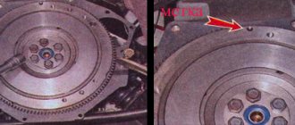
Installation of the drive gear of the VAZ and Lada Niva gearbox.
The second sign of a loose nut is the presence of axial play in the drive gear. Grasp the flange with both hands and move it back and forth (the car is on a stand, with stops under the wheels). The drive gear nut may be unscrewed a full turn or more (1 turn - axial movement - is equal to the thread pitch, i.e. 1.5 mm). Here we are no longer talking about preload and you are lucky that the gearbox is still working.
Step-by-step instruction
- Initially, of course, you need to dismantle the cylinder head cover itself.
- Then place a container under the bottom of the car to collect the used refrigerant. Replacing the cylinder head cover gasket. Unscrew the drain plug and drain the antifreeze.
- Then you should disconnect the throttle cable from the receiver and assembly.
- After this, the timing pulley should be removed along with the bearing housing.
- Next, we dismantle the valve lever, and then unscrew the lever supports themselves. Also dismantle the engine fluid supply ramp to the hydraulic supports.
- Now you need to disconnect the cable harness from the TPS. In the same way, disconnect the wiring from the idle speed sensor and antifreeze.
- You need to squeeze the plastic clip and then disconnect the connector with the wires that are designed to power the injectors. Here you also need to remember to disconnect the wiring harness from the knock sensor.
- Now disconnect the high voltage cables from the spark plugs. Also disconnect the cable that powers the engine temperature control device.
- Slightly compress and disconnect the exhaust pipe from the intake manifold. Then the upper screw securing the inlet tube spacer and, slightly loosening the lower screw, the spacer should be moved to the side.
- The clamp should be loosened slightly, then the adsorber purge pipe should be disconnected from the throttle assembly.
- The clamps must be loosened and the cooling system pipes must be disconnected from the cylinder head.
- Using open-end wrenches, you now need to disconnect the fuel lines. Replacing the fuel filter on a Chevrolet Aveo with your own hands, video instructions. To do this, unscrew the nuts of the fuel hoses intended for draining and supplying gasoline.
- Now use a wrench to remove the top screw that secures the rear intake tube brace. The bottom screw should also be loosened a little. Replacing the cylinder head gasket of Peugeot 206 1.4. After these steps, the spacer must be removed to the side.
- When all the above steps have been completed, the camshaft pulley drive chain tensioner should be removed.
- Then dismantle the brackets that secure the power steering device.
- Now you can remove the chain with the timing pulley star.
- After this, using a socket with an extension, you will need to unscrew the screws securing the cylinder head, and then dismantle it.
- Now you can remove the cylinder head gasket. Mount a new component in its place, having previously lubricated its perimeter with sealed glue. Actually, at this point the work on replacing the cylinder head gasket in the Chevrolet Niva can be considered completed. All further work on assembling the power unit must be performed in the reverse order. How to replace the cylinder head gasket on video 3 from the Niva Chevrolet cylinder head. But that is not all. To ensure a reliable fit of the cylinder head to the block itself, you need to correctly tighten the screws and maintain the tightening torque.
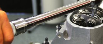
- The procedure itself consists of several stages. First of all, using a torque wrench and following the order indicated in the diagram, you need to tighten the screws from the first to the tenth. In this case, the tightening torque of the Niva Chevrolet cylinder head should be 20 Nm.
- Next, when all the bolts are tightened in turn, you need to tighten all the cylinder head screws again. The tightening torque should now be 69.4–85.7 Nm. The last, eleventh pulley needs to be tightened to 31.4–39.1 Nm.
- After these steps, the screws marked with numbers from one to ten need to be turned 90 degrees, and then, when they are all screwed, you should repeat the procedure and turn them again 90 degrees. At this point, the screw tightening procedure can be considered complete.
Read news about the new Niva
- No longer Chevrolet: Lada Niva returns - Autoreview
- Chevrolet Niva 2022 ALREADY IN RUSSIA! new body configuration and prices photo, video test drive
- The Chevrolet Niva with the face of Vesta will appear in 2022. Photo
- New Niva Chevrolet Lux 2022
- Production of the restyled Chevrolet Niva 2022 has started [photo]
- Lada Niva 2022 new body | Lada Niva Chevrolet prices and specifications for 2022 from an official dealer.
- Rear left wheel speed sensor (ABS) on Chevrolet Niva (VAZ 2123) | Motorring online store
- How to adjust the clutch on a Chevy Niva
Also interesting: Forward Safari 540 225/75 R16 91T – buy all-season tire, price comparison of online stores: photos, characteristics, description | E-Katalog
Front suspension
- Nut of the lower bolts securing the cross member to the body side members M 12×1.25 66.6-82.3 (6.8-8.4)
- Nut of the upper bolts securing the cross member to the body side members M 12×1.25 66.6-82.3 (6.8-8.4)
- Nut of the bolt securing the rebound buffer bracket to the cross member M8 15.1-18.6 (1.53-1.90)
- Nut of the upper arm axle mounting bolt M 12×1.25 66.6-82.3 (6.8-8.4)
- Nut securing the upper end of the shock absorber M10×1.25 27.4-34.0 (2.80-3.46)
- Nut securing the lower end of the shock absorber M10×1.25 50.0-61.7 (5.1-6.3)
- Front wheel hub bearing nut M 18×1.5 cm, “Chassis”, p. 169
- Bolt securing the caliper to the steering knuckle M10×1.25 29.1-36.0 (2.97-3.67)
- Anti-roll bar mounting nut M8 15.0-18.6(1.53-1.90)
- Nut securing ball pins to steering knuckle M 14×1.5 83.3-102.9 (8.5-10.5)
- Nut for fastening the brace to the suspension cross member M 12×1.25 66.6-82.3 (6.8-8.4)
- Nut for fastening the extension to the body M 16×1.5 104.9-169.5 (10.7-17.3)
- Nut connecting the lower arm axis to the cross member M 16×1.5 114.7-185.2(11.7-18.9)
- Nut for fastening ball joints to suspension arms M8 20.60-25.75 (2.10-2.63)
- Wheel bolt nut M 12×1.25 62.4-77.1 (6.37-7.87)
- Upper suspension arm axle nut M 14×1.5 63.7-102.9 (6.5-10.5)
- Nut of bolts securing the swing arm M 12×1.25 66.6-82.3 (6.8-8.4)
Adjusting the wheel bearing
To work, you will need an indicator and a torque wrench.
To prepare for adjusting the wheel bearing, you must perform the following operations:
- Secure the indicator by resting its leg on the hub near the adjusting nut.
- Place spanners on the studs and secure them with nuts.
- Rotate the hub and move it axially. (Screwed spanners are used as handles).
- Measure the amount of axial movement (clearance) of the hub, guided by the indicator readings.
- If the stroke exceeds 0.15 mm, adjust the play.
The adjustment is carried out as follows:
- Straighten the collar of the nut.
- Unscrew it with a spanner.
- Install a new nut and tighten with a force of 2 kgf*m.
- Loosen the nut and tighten again with a torque of 0.7 kgf*m.
- Loosen the tension by turning the key 20-25 degrees counterclockwise.
- Check hub play.
- Make sure that the indicator readings correspond to the norm (0.02-0.08 mm).
- Lock the nut by pressing its edge into the groove of the outer CV joint.
You can adjust the hub play without using a torque wrench. To do this you need:
- Tighten the nut tightly.
- Rotate the wheel a few turns.
- Check the play.
- If necessary, loosen or tighten the nut slightly.
- Continue until the free play of the hub is within 0.02-0.08 mm.
- Lock the nut collar.
The design of the rear wheel mounting of the Chevrolet Niva is very different. However, they also use bearings that need periodic replacement. They are replaced either together with the axle shafts or separately. The second option is much cheaper, but requires good metalworking skills and a torch to heat the metal.
To work you will need:
- Jack, wheel wrench, chisel, hammer.
- Standard set of screwdrivers and wrenches.
- Axle puller.
- Gas (gasoline) burner or muffle furnace.
- Repair kit including bearing, oil seal and retaining ring.
- A pipe with a diameter of 40-45 mm, the length of which exceeds the size of the axle shaft.
Replacement of bearings is carried out as follows:
- Place the machine on a level surface.
- Place wheel chocks or bricks under the front wheels.
- Jack up the car.
- Remove the wheel.
- Place a support under the rear axle.
- Unscrew the brake drum mount.
- Dismantle the part.
- Unscrew the nuts holding the bearing.
- Load the rear axle by lowering it onto the stand.
- Pull out the axle shaft using a puller.
- Hang the brake mechanism on a wire.
- Knock down the retaining ring using a chisel, hammer and grinder.
- Crack the bearing races using a chisel.
- Remove rust and dirt from the seating surface.
- Put the new bearing in place.
- Heat the locking ring to 200-250 degrees (dark red color) and hammer it into the seat with a pipe
- Replace the oil seal.
Draining antifreeze in Chevrolet
This is the first stage that is performed when replacing a damaged Niva gasket. Initially, you need to remove the mudguard and the lubrication sump housing - they are located in the engine compartment.
- reduce the pressure in the coolant supply system by opening the cap of the distribution tank (be sure to close it afterwards - this will reduce the antifreeze pressure);
- place a container of at least 9 liters under the drain (it is under the radiator on the left);
- unscrew the cap and wait until the liquid pours out;
- inspect the gasket of the drain plug - if it is worn out, replace it too;
- Remove the cap from the expansion tank again.
Now you need to get rid of the antifreeze remaining in the cooling system of the engine itself. To the left of the cylinder head, near the ignition unit, there is a separate drain hole. Place a container under it and unscrew the plug with a 13 key.
When the liquid flows out, tighten the radiator cap and cylinder head. In the latter case, a force of at least 25 N∙m will be required.
Torsion bolts (plastically deformable)
cylinder head bolt of a new type Part number: 21213-1003271-01-0. Name: Torx cylinder head bolt. This name (torsion bar bolts) is fundamentally incorrect, but what can you do if they are called that on all forums and in all stores. According to science, when they say torsion bar, they mean deformation from twisting. And in this case, tensile deformation. In stores, these bolts are also called cylinder head bolts for Niva Chevrolet or cylinder head bolts of a new type. I also came across the name torx or chamomile. These bolts, unlike hardened ones, provide a constant load. That is, in a very primitive way we can talk about the grommet effect, that is, about the constant force to compress the cylinder head gasket in the axial direction of the bolt. These bolts are widely used on imported engines because they avoid human factor errors. In fact, you don't need to tighten with the precision of a torque wrench. The final values are taken as angular values. I don’t really like this approach, but such things are now commonly called “assembly guarantee”.
Why change the mount?
There are several reasons why Niva car owners change their wheel nuts to new ones:
Old nuts that are worn or mechanically damaged do need to be replaced, especially when they have poor threads or missing edges. It is difficult to tighten such a part with a torque of 10-11 kgf/m to securely fasten the wheel. It’s better to install a new set; it’s pointless to change 1-2 fasteners. The main thing is that the threaded part of the stud remains normal.
Alloy wheels, although thicker than stamped steel ones, can theoretically be fastened with factory nuts. Another thing is that such details will ruin the entire appearance of the new wheels, so in such a situation it is better to install elements that are in harmony with the wheel. There is another point: in some models of alloy wheels, samples are made in the form of a hemisphere, rather than a cone. Then the standard fasteners will definitely not fit; you need to purchase nuts with a spherical end that fit into the mating part of the rim.
In addition to improving the appearance of the car, there is another reason that forces you to change 1 out of 5 nuts to a special one that can only be turned with an exclusive key. The reason lies in the high cost of car tires and storing the car itself in the open air in the yard, as often happens in cities. To prevent tires from being stolen at night, one clever security nut is installed on the car.
How hard should you tighten the wheel nuts?
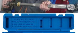
The tightening force for the bolts is different for each car and is determined by the manufacturer, indicating it in the operating instructions for the model.
But how do you understand that when twisting, exactly the force that is needed is applied? And how not to overdo it and not break the thread? For this purpose, there is a special wrench with a built-in dynamometer (hence the name dynamometer). It will provide control of the tightening torque of wheel nuts, for which pinching is as undesirable as weak fastening.
It can lead not only to thread breakage or deformation of a bolt or stud, but also to the appearance of a crack on the disk. In addition, overtightened fasteners tend to stick to the hub, after which it is impossible to unscrew it - you just need to cut it off. You can tighten the threads not only with a wrench, but also with a bolt gun, the lever of which is of sufficient length.
Therefore, after screwing the fasteners with a conventional tool, it is recommended to final tighten the bolts with a torque wrench. With its help, the connection can be either tightened to the specified level or weakened if excessive force was initially applied.
Maximum and minimum possible parameters of non-standard disks
Some car owners strive to install beautiful wheels of a larger size on their car than those supplied by the manufacturer. The Nyva Chevrolet body allows this to be done thanks to the design of the car's wheel arches. Wheel sizes that do not require modifications to the body are considered 215/75 with a minimum offset of 35.
If the driver has installed a tire with a profile over 215mm, then the arches will have to be trimmed a little, and the ET offset should exceed 58mm. The most optimal reach size is 40-45. Therefore, when planning the installation of new wheels and tires, you need to carefully study this issue. To do this, special websites are offered to help the car enthusiast, where on videos and photos you can see in detail the entire procedure from choosing a wheel to replacing it.
Properly selected wheels and tires are the key to stable vehicle performance on the road.
Tightening scheme
Using a large screwdriver, the chain tensioner is removed, then the camshaft gear is placed in its original place. The bolt and washer are tightened. The latter is controlled with pliers.
Next, the thermal clearance of the valves is adjusted. Assembly is carried out in reverse order.
Video 2: replacing the timing tensioner.
How to disassemble and reassemble the cylinder head
Knowing the procedure for replacing a faulty element, you can carry out repair work yourself in your garage. But still, it is best to contact a specialist, since even a minor inaccuracy during work can lead to very serious consequences.
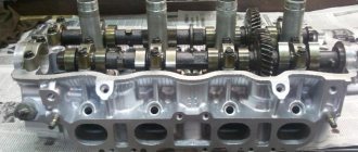
Device
The unit parts are housed in a durable metal case that protects the mechanism from damage. Gear oil is used to lubricate rotating parts.
The force of the propeller shaft, screwed to the flange on the shank of the unit, is transmitted to the drive gear. Next, through the satellites, the torque is distributed between the axle gears (left and right).
The gearbox mechanism also includes bearings, nuts, gaskets, and adjusting rings. Plugs are provided for filling oil and removing waste into the housing. The drive gear, like the axle shafts, is equipped with oil seals that prevent transmission leakage while the vehicle is moving. The figure shows the gearbox design in detail:
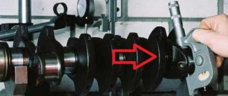
Chevrolet Niva › Logbook › Crankshaft pulley and gas rack
This morning I needed to go to the garage. At the same time I decided to throw a “blanket” over the engine.
After a long stay in the cold, switching to gas occurred intermittently due to “sticking” of the gas injectors. Enabling the “injector warming” function in the gas ECU improved the situation, but not by much. But turning on the “blanket under the hood” function had a noticeable effect!
I arrive at the garage, open the hood...the picture is as follows:
Without lowering my head, I wonder what’s going on there.