Share:
Here is the tightening torque for a VAZ 2108 car of different thread connections. It includes the tightening torque of the VAZ 2108 camshaft and the tightening torque of the VAZ 2108 car with an 8-valve engine. It includes the tightening torque of the bolts and the tightening torque of the VAZ 2108 hub. The tightening torque of the engine combines the tightening torque of the camshaft and the tightening torque of the cylinder head of the VAZ 2108 8 valves. And the tightening torques for threaded connections of the VAZ 2108 include the tightening torque of the rear hub and the tightening torque of the main VAZ 2108.
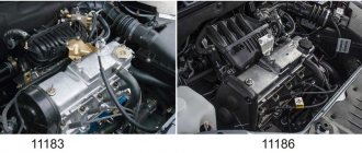
VAZ 2108 engine tightening torque
Tightening torque for the cylinder head of the VAZ 2108 engine:
- The M12XI.25 bolts for securing the cylinder head must be tightened 4 times:
- torque - 20 N*m;
- times with force - 6 9.4-85.7 N*m;
- once - turn 90°;
- once - turn it 90°.
- M6 nuts for attaching the cylinder head cover with a force of 1.96-4.6 N*m
Tightening torque of the camshaft of the VAZ 2108 engine 8 valves:
- M8 nuts for studs securing the camshaft bearing housing with a force of 18.38-22.64 N*m;
- M10 bolts for attaching the camshaft pulley with a force of 67.42-83.3 N*m;
VAZ 2108 bolt tightening torque:
- M6 bolts for fastening the housing of assisting devices with a torque of -0.68-0.84 N*m;
- M6 bolts for fastening the oil sump with a force of 5.15-8.23 N*m;
- Hardware M6 for connecting the Tasol pump with a torque of 7.64-8.01 N*m;
- M6 bolts for fastening the supply tube of the antifreeze pump with a force of 4.17-5.15 N*m
Tightening torque for main car VAZ 2108:
- Bolts M10X1.25 for connecting the main bearing caps with a force of 68.31-84.38 N*m;
- M6 hardware for connecting the oil receiver to the main bearing tire with a force of 8.33-10.29 N*m
Tightening torque for VAZ 2108 engine connecting rods:
- Nut M9x1 of the connecting rod cap bolts with a torque of 43.32-53.51 N*m
Tightening torque of the VAZ 2108 flywheel bolts:
- Bolts M10x1.25 for fastening the flywheel with force - 60.96-87.42 N*m
Tightening torque of the crankshaft of the VAZ 2108 engine:
- Bolts M12x1.25 for connecting the crankshaft pulley with a force of 97.9-108.78 N*m
Tightening torque for VAZ 2108 nuts:
- Nuts M8x1.25 for attaching the exhaust pipe of the muffler with a torque of 20.87-25.77 N*m
- Nut M8x1.25 fastening the additional muffler flange with a force of 15.97-22.64 N*m
- Nut M12x1 for connecting the clutch cable to the motor bracket with force - N*m
- M10 nut for the bolt attaching the front propulsion suspension support with a torque of 41.65-51.45 N*m
| VAZ engine tightening torque table | ||
| Name of propulsion devices and parts | Thread | VAZ 2108 engine tightening torque, N*m |
| Stud nuts securing the intake pipe and exhaust manifold | M8 | 20,87-25,77 |
| Tension roller connection nut | M10x1.25 | 33,23-41,16 |
| Stud nuts for connecting the outlet pipe of the cooling jacket | M8 | 15,97-22,64 |
| Nut for connecting the exhaust pipe of the muffler | M8x1.25 | 2,13-2,63 |
| Bolts for connecting the engine front support bracket | M10×1.25 | 32,2-51,9 |
| Nuts of bolts connecting the left motor support | M10 | 41,65-51,45 |
| Nuts for attaching the left engine mount bracket | M10 | 31,85-51,45 |
| Bolt for fastening the rear propulsion suspension support | M10×1.25 | 27,44-34 |
| Nuts of bolts connecting the rear engine mount bracket | M12 | 60,7-98 |
| Bolts connecting the oil receiver to the pump | M6 | 6,86-8,23 |
| Oil pump attachment bolt | M6 | 8,33-10,29 |
| Bolts for attaching the oil pump housing | M6 | 7,2-9,2 |
| Oil pump bypass valve plug | M16×1.5 | 45,5-73,5 |
| Oil filter fitting | M20x1.5 | 37,48-87,47 |
| Oil pressure sensor | M14x1.5 | 24-27 |
| Carburetor attachment nut | M8 | 12,8-15,9 |
Note! 10 N*m = 1 kgf*m
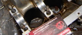
Installing the connecting rod and piston group
The connecting rod and piston group (CPG) must be installed as an assembly. It is not recommended to press the piston pin into the connecting rod head without special tools. This procedure is best left to professionals.
To install the ShPG, you need a steel mandrel in the shape of a ring. The height of the ring is 2-3 cm, the diameter of the hole is slightly larger than the diameter of the cylinder. The pistons must be mounted in such a way that the arrow on their bottom (the part adjacent to the valves) is turned towards the oil pump. The number of the connecting rod and piston must correspond to the number of the cylinder. Before installation, you need to separate the locks of the oil scraper and compression rings at an angle of 120 degrees.
- Turn the block over.
- We wipe the cylinder walls and crankpins with a dry cloth.
- Thoroughly lubricate the cylinder walls, the side surfaces of the pistons and the inside of the mandrel with oil.
- We place the mandrel on the cylinder and insert the piston and connecting rod assembly through it. We push the piston into the cylinder using a round wooden stick (hammer handle).
- Place the liner in the connecting rod cover and lubricate it with oil.
- We lay the block on its side and install the connecting rod cap so that the cylinder number on it and on the connecting rod are on the same side. We secure the cover with nuts.
- In the same way we mount the remaining pistons and connecting rods. After this, turn the cylinder block upside down and tighten all 8 nuts securing the connecting rod caps.
If you don't have a mandrel, you can cut it yourself from a piece of thick-walled steel pipe.
Tightening torque for VAZ 2108 clutch threaded joints
Tightening torque of clutch bolts VAZ 2108:
- Bolts M12x1.25 fastening the clutch housing to the engine block with a force of 54.2-87.6 N*m;
- Bolt M8 attaching the clutch housing to the flywheel with a torque of 19.13-30.9 N*m;
- Bolt M6 fastening the bottom cover to the clutch housing with a force of 3.8-6.2 N*m
| List of devices and connections | Thread | Tightening torque of clutch parts VAZ 2108, N*m |
| Nut securing the clutch housing to the engine block | M12x1.25 | 54,2-87,6 |
| Bolts for connecting the flange of the clutch release bearing guide sleeve | M6 | 3,8-6,2 |
| Nut for attaching the clutch housing to the gearbox | M8 | 15,7-25,5 |
Healthy ! VAZ 2108 diagram
When is it necessary to remove the cylinder head?
On cars that came off the assembly line of the Volzhsky Automobile Plant, regardless of how many valves the power unit has and which drive (rear or front) is used, tightening is carried out after disassembling the cylinder block. As noted above, usually dismantling the head is needed to replace the gasket, the service life of which is 60,000 or a maximum of 80,000 kilometers. The deterioration of the sealing element seriously affects the operation of the engine, and therefore it is better not to use the machine until it is repaired.
Often the gasket wears out between the communications through which lubricant and coolant circulate. As a result, mixing of such different compositions occurs and their mutual contamination. As a result, both of them noticeably lose their operational suitability. The following symptoms are typical for this failure:
- the oil becomes thinner (sometimes the level drops or rises);
- Antifreeze takes on a brownish tint.
Repair in this situation is urgently needed.
Another problem often encountered on 8-valve VAZ-2108 is a leak in the area between the coolant supply system and the combustion chamber. This happens in the following cases:
- insufficient tightening torque;
- uneven tightening of bolts;
- factory defective gasket.
Regardless of the reason, air is directed into the cooling circuit, which leads to heating of the antifreeze. An obvious sign of trouble is strong bubbling of the fluid in the distribution tank.
It is extremely rare to see damage to the gasket in the area between the cylinders. If this happens, then compression decreases, which leads to unstable engine operation.
Often such problems arise a short time after replacing the cylinder head gasket. In this case, car owners spend a lot of effort trying to find the cause, and cannot even think that the named sealing element or incorrectly tightened head bolts are to blame. Therefore, knowledgeable craftsmen recommend first checking whether the joint between the cylinder head and the block is airtight. If characteristic streaks appear on the motor housing in the area of the head, then there is no point in looking further.
VAZ 2108 gearbox tightening torque
Tightening torques for threaded connections of the VAZ 2108 gearbox:
- Threaded connection of the drain plug M22x1.5 with a torque of 28.7-46.3 N*m
- Threaded connection M14x1.5 for reverse light switch with force - 28.4-45.3 N*m
| List of devices and parts | Thread | Tightening torque of VAZ 2108 gearbox parts, N*m |
| Conical screw fastening the drive rod joint | M8 | 16,3-20,1 |
| Gear selection mechanism connection bolt | M6 | 6,4-10,3 |
| Shift Lever Housing Fastening Bolts | M8 | 15,7-25,5 |
| Nuts for connecting the drive rod clamp and jet rod | M8 | 15,7-25,5 |
| Nuts of the rear ends of the primary and secondary shafts | M20x1.5 | 120,8-149,2 |
| Bolts securing the forks to the rod | M6 | 11,7-18,6 |
| Differential driven gear mounting pin | M10x1.25 | 63,5-82,5 |
| Speedometer drive housing connection nut | M6 | 4,5-7,2 |
| Metis fastening axis of the gear selector lever | M6 | 11,7-18,6 |
| Nuts connecting the rear tire to the gearbox housing | M8 | 15,7-25,5 |
| Reverse fork lock plug | Ml 6×1.5 | 28,4-45,3 |
| Conical screw for connecting the gear selector rod lever | M8 | 28,4-35 |
| Bolts for connecting the clutch housing and gearbox | M8 | 15,7-25,5 |
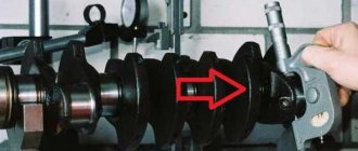
Flywheel mounting diagram
For the convenience of the user, auto manufacturers shift the axis of one threaded hole for the flywheel bolts by several degrees, so it is physically impossible to install this part incorrectly. However, drivers usually take additional precautions by marking them with paint during dismantling.
Mark when dismantling the flywheel
By analogy with flange connections, 6 bolts are used here, screwed into the crankshaft body, located at 60 degrees, except for one specially offset. For this formula of a threaded connection, tightening according to a special scheme is used, since there is no full-fledged “cross” here:
- two bolts opposite each other along the diameter axis;
- two bolts next to the previous ones in the same sequence;
- the remaining two bolts follow the same principle.
Diagram for six bolts
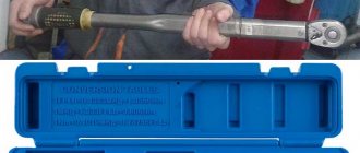
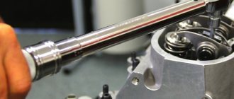
Attention: It is prohibited to use tubular “amplifiers” and extend keys. Instead, a torque wrench should be used.
Torque wrench
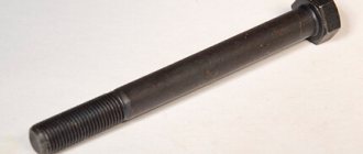
Why does the bolts cut off?
When asked whether it is necessary to change the bolts for fixing the flywheel on the crankshaft, each manufacturer answers in advance, in the operating instructions - if possible, with each disassembly of this unit. A bolt can be cut for several reasons:
- the occurrence of backlash when unscrewing, an increase in the lever for shearing forces;
- incorrect choice of bolt strength class.
Sheared flywheel bolts
When retightening the thread, the working forces cannot cut the bolt, since the fasteners simply fall out due to the cut threads.
Fastener selection
To prevent the fastening element from breaking during engine operation, designers calculate the bolts based on loads. Known data are:
- axial and transverse load;
- operating temperature conditions;
- number of bolts in the connection.
Depending on the steel grade, the shear force of the thread and the bolt body and the tensile force are calculated. Since bolts are standard parts, they are produced and classified according to the GOST standard, and for specific connections of assembly units they are selected according to the following criteria from the tables of these GOSTs:
- strength class;
- steel grade;
- preparation method;
- type and number of splines;
- overall dimensions (thread diameter and length).
The tightening force is determined automatically, but from other tables according to the strength class. Additionally, depending on the number of bolts in the assembly connection and their relative position in space, various pulling schemes are used.
The most popular pattern is the “cross”, when the bolts are pulled opposite each other on one axis to a specific force value, then others, but along the axis, at right angles to the previous one.
In the formula for bolting a flange with 6 bolts, the “cross” pattern does not work, since the axes are shifted, not by 90, but by 60 degrees relative to each other, so another sequence is selected, as indicated above and further along the course of this guide.
Strength class
Traditionally, any product produced industrially contains materials with the lowest possible manufacturing cost, providing the necessary margin of safety.
In other words, bridge and crane bolts, considered the most reliable, made from high-strength steels, are too expensive for unloaded connections. This is not economically feasible and is not used in practice.
Although, if desired, any user can use these standard parts so that they are guaranteed not to be cut off by the flywheel during operation.
Crane bolt
According to the GOS 1759.4 classification, there are 11 bolt strength classes: 3.6, 4.6, 5.6, 5.8, 6.6, 6.8, 8.8, 10.9 and 12.9. Two marking numbers separated by a dot indicate:
- the first – multiplied by 100, indicates the tensile strength of the metal in N/mm2;
- the second - multiplied by 10, indicates the ratio of the yield strength to the onset of irreversible plastic deformation in percent.
When choosing a standard threaded part, a minimum safety margin of two times the last value is included in the connection, ideally a safety factor of three times. For example, tower and bridge cranes use bolts of class 8.8 and higher.
Manufacturing method and materials
The strength class is determined by two factors - the grade of steel and the method of manufacturing the bolt. It is virtually impossible to strip threads or shear a cold/hot headed bolt. The thread is formed on the body of the workpiece by automatic rolling, undergoes heat treatment, and is coated with a protective compound.
The carbon content in the rods cannot exceed 0.4% - alloy and low-carbon steels 40Kh, 65G, 20G2R, 20KP, 10KP and others. Heat treatment is carried out in a layer of protective gas to completely preserve the carbon content.
Steel 35 is considered a universal material that allows you to obtain different strength classes through the use of different technologies:
- bolts of class 5.6 are made from it on screw-cutting lathes;
- by volume stamping on upsetting presses they obtain class 6.6 or 6.8;
- after hardening of parts produced by previous methods, class 8.8 is achieved.
Turned bolt
Manufacturing of bolts by stamping
Hardened bolts
For other steels, the table of strength classes is valid:
Dependence of strength class on material
To fix the flywheel, M8 - M12 bolts are used, and marking is mandatory for standard products from M6 and above. However, products turned on a machine are very rarely branded to reduce costs. On stamped and knurled bolts, markings are present on the end or edges of the head.
Marking location on bolts
Tightening torque of threaded connections of the front suspension of VAZ 2108
Tightening torque for the VAZ 2108 hatchback hub:
- Nut M20xl.5 for rear wheel hub bearings with a force of 186.3-225.6 N*m;
- Nut M20xl.5 for front wheel hub bearings with a torque of 225.6-247 N*m.
| Name of devices and connections | Thread | Tightening torque of threaded connections VAZ 2108, N*m |
| Nut securing the upper support to the body | M8 | 19,6-24,2 |
| Wing for connecting the ball pin to the lever | M12XI.25 | 66,6-82,3 |
| Nut of the eccentric bolt for attaching the telescopic strut to the steering knuckle | М12Х1.25 | 77,5-96,1 |
| Hardware for attaching the telescopic strut to the steering knuckle | M!2xl,25 | 77,5-96,1 |
| Pins and nuts for connecting the suspension arm to the body | M12×1.25 | 77,5-96,1 |
| Nuts for connecting the brace | M16x 1.25 | 160-176,4 |
| Hardware for fastening the stabilizer bar to the control arm | M10xl,25 | 42,1-52,0 |
| Nuts for attaching the stabilizer bar to the body | M8 | 12,9-16,0 |
| Bolts for attaching the brace bracket to the body | M10x1.25 | 42,14-51,94 |
| Wing for connecting the telescopic rack rod to the upper support | M14x1.5 | 65,86-81,2 |
| Bolts for attaching the ball joint to the steering knuckle | M10x1.25 | 49-61,74 |
| Wheel bolts | M12xl,25 | 65,2-92,6 |
Problems when paying with bank cards
Sometimes difficulties may arise when paying with Visa/MasterCard bank cards. The most common of them:
- There is a restriction on the card for paying for online purchases
- A plastic card is not intended for making payments online.
- The plastic card is not activated for making payments online.
- There are not enough funds on the plastic card.
In order to solve these problems, you need to call or write to the technical support of the bank where you are served. Bank specialists will help you resolve them and make payments.
That's basically it. The entire process of paying for a book in PDF format on car repair on our website takes 1-2 minutes.
Source
Tightening torque for the rear suspension threads of the VAZ 2108
| Name of devices and parts | Thread | Tightening torque of threaded connections VAZ 2108, N*m |
| Nuts for connecting the lower end of the shock absorber | M12x1.25 | 66,6-82,3 |
| Rear suspension arm articulation wings | M12x1.25 | 66,6-82,3 |
| Nuts for fastening the suspension arm brackets | M10x1.25 | 27,4-34 |
| Hardware for connecting the upper end of the shock absorber | M10x1.25 | 50-61,7 |
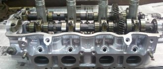
Removing and installing the camshaft
| GENERAL INFORMATION |
Camshaft and valve drive of a 4-cylinder petrol engine
| 1. Main bearing caps 2. Nut, 20 Nm 3. Key (operating without tightening) 4. Camshaft 5. Valve cotters 6. Outer and inner valve springs 7. Valve guide. Repair version with collar 8. Cylinder head 9. O-ring | 10. Valve guides 11. Valves 12. Plug 13. Plug 14. Lower valve spring retainer 15. Oil seal 16. Upper valve spring retainer. Designation: wide chamfer on the outside, chamfer on the inside 17. Hydraulic disc pusher |
4-CYLINDER PETROL ENGINE
Removal
| EXECUTION ORDER |
| 1. Remove the upper timing belt guard. |
| 2. Remove the cylinder head cover. |
| 3. Set the crankshaft to the TDC position for cylinder 1 (see subsection 2.5.2). |
| Warning Do not change the position of the engine crankshaft again. |
| 4. Loosen the toothed belt and remove it from the top of the camshaft gear (see subsection 2.5.1). |
| 5. Wedge the camshaft at the front with a spike. To do this, insert a suitable spike or a strong screwdriver into the hole of the camshaft gear and press it against the upper edge of the cylinder head. To avoid damage to the sealing surface of the cylinder head, use a wooden gasket. Hold the screwdriver firmly and loosen the camshaft bolt. Unscrew and remove the camshaft gear, if necessary, drive it in with light blows of a rubber hammer. Remove the key from the camshaft. |
| 6. Mark all main bearing caps. Four covers, from right to left, looking in the direction of travel, mark them with numbers from 1 to 4. |
| 7. Remove covers 1 and 3. Then unscrew covers 2 and 4 alternately crosswise. |
| 8. Remove the camshaft. |
| Warning If the disc pushers are removed, they must be marked so that they can be installed again in their original places. Place the disc tappets with the sliding surface (moving towards the camshaft) down. |
Installation
EXECUTION ORDER
1. Before installation, if necessary, you can check the camshaft runout at the factory. Wear limit: 0.01 mm. 2. If the old camshaft is installed again on an engine with high mileage or noise in the valve drive, it is recommended to check the axial clearance. Wear limit: 0.15 mm. The measurement is carried out with the poppet tappets removed and the first and last main bearing caps installed. 3. Install a new camshaft sealing ring. Pre-oil the lips and the outer edge of the O-ring.
4 Make a trial installation of the bearing caps, paying attention to the position of the centers. The covers must be installed so that the holes in the covers and the cylinder head match. When doing this, pay attention to the marks.
5. If the disc pushers were removed, install them in their original places. Lubricate the disc pushers with a thin layer of oil and do not distort them during installation.
Warning Disc pushers cannot be swapped!
6. Lubricate with oil and install the camshaft.
Warning In this case, the cams of cylinder 1 must be directed upwards. Install the bearing caps according to the marks. Pay attention to the position of the centers.
7. Tighten covers 2 and 4 crosswise to a torque of 20 Nm.
8. Install covers 1 and 3 and tighten to 20 Nm.
9. Install the camshaft key. Install the drive gear and tighten to a torque of 80 Nm, while holding the gear with a spike.
10. Place the toothed belt on the camshaft gear, paying attention to the correct position of the intermediate shaft and vibration damper (see subsection 2.5.2).
11. Tension the toothed belt (see subsection 2.5.1).
12
Install a new cylinder head cover gasket, carefully tightening the cover bolts to a torque of 10 Nm.
13. Install the toothed belt guard.
Warning If new disc tappets are installed, the engine must not be started for approximately 30 minutes, otherwise the valves will hit the pistons!
Steering torque
| List of mechanisms and connections | Thread | Tightening torque of threaded connections VAZ 2108, N*m |
| Steering gear housing fastening nuts | M8 | 15-18,6 |
| Nuts for connecting the steering shaft bracket | M8 | 15-18,6 |
| Steering shaft bracket fastening bolts | M6 | Wrap until the head comes off |
| Bolt attaching the steering shaft to the gear | M8 | 22,5-27,4 |
| Steering wheel mount | M16x1.5 | 31,4-51 |
| Tightening hardware for steering rod end | M10 | 19,1-30,9 |
| Ball pin joint nut | M12x1.25 | 27,05-33,42 |
| Bolts securing the steering linkage to the rack | M10xl | 70-86 |
| Steering gear bearing nut | M38x1.5 | 45-55 |
Video “Eliminating knocking”
This video (Car Owner channel) shows the operation of a VAZ 2114 8 cl engine with a knock. And what is the way out of this situation?
The camshaft on VAZ 2109-2108 cars has to be changed quite rarely, and this should only be done if there is noticeable wear on the journals and cams. You can even check it without special equipment with your hands: by running your fingernail across the balls and cams across the cams, your finger should not catch on anything, that is, there should be no grooves or irregularities. If you can even feel wear with your finger, the camshaft must be replaced with a new one.
All work on removal and installation is carried out without any problems, even at home, because even for such a seemingly complex job, very few tools are needed. The list of what you need is given below:
- 5mm hex or similar bit with holder
- 13 open-end or socket wrench
- Socket head 10 deep
- Extension
- Ratchet handle
Before we begin performing this repair, we will need to complete the following steps:
- Remove the air filter
- Remove the fuel pump
- Dismantle the distributor
- Remove the camshaft sprocket, first removing the timing belt from it. Read more about this here.
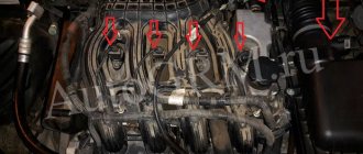
Also, you need to disconnect the auxiliary units drive housing, on which, by the way, the distributor is installed. To do this, you will need a hexagon, where we unscrew the bolt securing the housing:
And then we disconnect it, if necessary prying it with a thin flat screwdriver at the junction with the cylinder head:
Then you can start unscrewing the camshaft housing mounting nuts on the VAZ 2109-2108, and in total you will have to unscrew 10 pieces. They are all marked in the photo below:
If you plan to replace the body with a new one, then you need to unscrew the valve cover mounting studs from the old one, turning them out using a deep socket and a ratchet. After which you can remove the housings, short and long, since nothing else holds them:
Well, all that remains is to remove the camshaft itself from the bed, lifting it up:
If the shaft needs to be replaced, then a new one can be bought at almost any auto parts store, the price of which for a VAZ 2109-2108 is between 800-900 rubles. Installation is carried out in the reverse order of removal and it is worth paying attention that when replacing the camshaft, you will have to adjust the valves after assembly - accordingly, buy new adjusting washers of the appropriate size.
Tightening torque for VAZ 2108 brake threads
| List of mechanisms and connections | Thread | Tightening torque of threaded connections VAZ 2108, N*m |
| Bolts connecting the brake cylinder to the caliper | Ml 2×1.25 | 115-150 |
| Hardware for connecting the guide pin to the cylinder | M8 | 31-38 |
| Bolts attaching the brake to the steering knuckle | M10x1.25 | 29,1-36 |
| Pin for connecting the rear brake to the axle | M10x1.25 | 34,3-42,63 |
| Wings for attaching the vacuum booster bracket to the bracket booster | M8 | 9,8-15,7 |
| Nuts for connecting the main control unit to the vacuum booster | M10 | 26,5-32,3 |
| Nuts securing the vacuum booster to the bracket amplifier | M10 | 26,5-32,3 |
| Brake pipe joint fittings | M10 | 14,7-18,16 |
| Front brake flexible hose fitting | M10x1.25 | 29,4-33,4 |
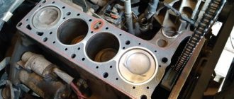
Reinstalling the head
Now you can carefully install the cylinder head in its place, making sure that at this moment the gasket does not slip out or move to the side. Of course, the guides fix it, but you should still be extremely careful.
Next, we will need a torque wrench, since the bolts will have to be tightened with a certain torque. It is also worth keeping in mind that the tightening order must be observed. The diagram below shows the sequence in which to twist:
Now regarding the force with which it is necessary to tighten the bolts. This should be done in 4 steps:
- First, a torque of 20 Nm
- Second reception with a torque of 75-85 Nm
- Tighten each bolt another 90 degrees.
- Finally turn it 90 degrees.
After this, all that remains is to install all the equipment removed from the car, fill in the coolant, connect all the sensors, wires and hoses and check the work done. Usually everything becomes visible immediately after pouring antifreeze. If wet marks appear at the junction of the head and block, you can take everything back and do the whole job again! But I hope that this will not happen in your practice! Happy renovation!
FakeHeader
Comments 13
I tightened it with a torque wrench and set it to 200 n.m. According to the book from 190 to 210
On P2 they are adjustable and loosening is necessary so that the bearing has a slight play, which will disappear when it warms up during movement, otherwise it will “burn out” and jam, the service life will decrease quickly. And here I think about the tightening torque of the CV joint (you can look at the approximate tightening torque on other brands by analogy). And so, of course, you don’t have to pull to break off the CV joint or rip off the nut))), but you already have to be a jock or have a 3 meter wrench)).
On P2 it was written to tighten with a certain force and then unscrew by 10 or 20 degrees) but who knows, you need to read the book)
Tighten it as much as possible, it’s not scary.
the maximum can be different, but it’s probably still too much, it’s completely impossible, then there is a certain amount of force with which to tighten it.
On the second generation of sports it is not adjustable, if you have play that you can feel with your hands, then just change it. I changed it for myself, installed the original on one side of the hub assembly, and then slowly bought the original bearing, disassembled the old hub and pressed in a new bearing, and then changed the other side. By the way, the bearing is KOYO in the original, if that :). I bought the hub for 6300 rubles (maybe more expensive now), and the bearing was about 3 thousand.
View Queue
Queue
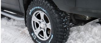
Wheel bearing diagnostics, causes and signs of failure
Let us briefly list the signs of this breakdown:
- Noise when driving from the front (right or left), and when turning there is also a noise or howling.
- Vibration in the interior is a sign that repairs are required, as the lubricant may have dried out or a lot of dirt has entered.
- A grinding or crunching sound means that the front wheel bearing has already fallen apart.
Before jumping to conclusions, do a step-by-step diagnosis:
- Jack up the side where there are characteristic signs, but before doing this, remove the wheel.
- Rotate the disk by hand; if there is a “rolling” sound or other noise, a replacement is needed. When the product is in good working order, rotation is smooth, without jamming or noise.
- Remove the brake disc, check the hub play by moving it by hand in the axial direction - if you feel the movement without measurements, then the front hub bearing needs to be replaced.
Reasons for failure:
- Not economical driving, over pits and potholes in the asphalt.
- Frequent overheating of the mechanism.
- Damage to the boot, contamination of the spare part from the inside.
- Wear of the product according to the warranty service life (60 thousand km stated).
- Malfunction of other elements (the brake disc is unbalanced, the rotating mechanism is worn out or the wheels are unbalanced, etc.).
Be sure to watch the video on how to check a wheel bearing:
How to check a wheel bearing
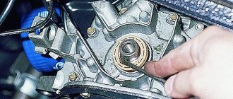
Are you here
By correctly determining with what force to tighten the hub nut and stopping in time, you can avoid stripping the threads and the need to perform expensive repairs, taking into account today's prices for nuts. Craftsmen perform this work using a special torque wrench. Since a wheel bearing is a rather capricious product and additional equipment is not always at hand, it is very important to know the answer to this question.
Before work, it doesn’t hurt to determine what type of it is installed, for example, it can be conical or roller.
Assembly
– that’s it, we begin the process of assembling the rear hub bearing on the VAZ 2109, 2110. To do this, we put the hub on the axle (by removing the bolt with which we tightened the cages);
– tighten and tighten the central nut (be sure to install a new one), not forgetting to put the thrust washer;
– put on and screw on the brake drum and wheel;
– check the rotation (there should be no extraneous noise);
– if all is well, lower the car from the jack;
– tighten the wheel and the central nut (the tightening torque of the hub is approximately 20 kgm, this is quite a strong tightening, if you don’t have a torque wrench, you need to use a lever of at least a meter to tighten the nut with a force twice the tightening force of the wheels);
– tighten the hub nut and tighten the wheels.