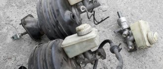
Problems that arise with the brakes while traveling are considered critical and must be corrected immediately. The culprit of the malfunction is often the main cylinder, installed in the engine compartment and rigidly connected to the pedal. To find out the cause of the breakdown and repair the unit yourself, you need to know the structure of the brake master cylinder (MBC) and its principle of operation. During the diagnostic process, it is necessary to distinguish and filter out problems with other elements of the system.
Replacing the master cylinder of the Lada Kalina brakes
If the piston of the master cylinder jams (due to corrosion, breakage of the return springs), incomplete release of the brakes on all wheels may occur.
A defect such as “failure” of the brake pedal may also occur
Rebuilding the master cylinder often does not lead to the desired results, so it is recommended to replace the master cylinder assembly.
Replacing the brake master cylinder
Remove the battery and the air supply hose to the throttle body.
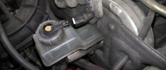
Having unscrewed the tank cap, remove the cap along with the liquid level sensor. Use a rubber bulb to remove liquid from the tank.
Use a rubber bulb to remove liquid from the reservoir.
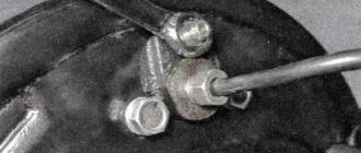
Using a 13 mm wrench or a special wrench for brake pipes, unscrew the fittings of the two brake pipes.
We remove the tube tips from the holes of the master brake cylinder.
Using a 13mm socket, unscrew the two nuts securing the cylinder to the vacuum brake booster
Remove the brake master cylinder assembly with the reservoir.
The connection between the master cylinder and the vacuum brake booster is sealed with a rubber ring.
To remove the tank, press out the two tabs of the tank body and remove them from the bosses of the cylinder body.
Overcoming the resistance of the rubber sealing bushings, remove the tank fittings from the cylinder holes and remove the tank
If it is necessary to replace the sealing sleeve, remove it from the cylinder body
We assemble the brake master cylinder with the reservoir and install it in the reverse order.
We bleed the hydraulic brake system.
Source
Removal and installation of TPS
Removal
1. Turn off the ignition.
2. Disconnect the wire from the negative terminal of the battery (spanner 10).
3. Disconnect the wiring harness connector from the sensor.
4. Unscrew the two screws securing the sensor to the throttle pipe and remove the sensor from the throttle pipe (using a Phillips screwdriver).
Installation
1. Install the sensor on the throttle pipe. In this case, the throttle valve should be in the normally closed position.
2. Tighten the two sensor mounting screws (Phillips screwdriver).
3. Connect the wiring harness block to the sensor.
4. Connect the wire to the negative terminal of the battery (spanner 10).
5. Check the sensor output signal as follows:
- connect the diagnostic tool, select the “Parameters” mode; ADC channels, POL.D.Z.”;
- with the ignition on and the throttle valve closed, the sensor output voltage should be 0.3...0.7 V. Then slowly open the throttle valve - the sensor output voltage should increase to 4.1...5 V. If it is outside the ranges, replace sensor.
Common GTZ malfunctions
Like any other mechanism, the GTZ has its own characteristic problems. One such problem is excessive pad wear and brake fluid leakage. As a result, the liquid level drops. If such a violation occurs, operation of the vehicle is prohibited until the problem is completely eliminated. In such a situation, you should definitely check the working and master cylinders, hoses and brake pipes, as well as the brake calipers for leaks. If a leaking part is found, it must be replaced. If the violation concerns the automatic drum brake adjustment system, this may be accompanied by a low brake pedal. In this case, you will need to restore the pedal travel manually. To completely eliminate the problem, you will need to completely clean the automatic adjustment system. Also, the problem can often be caused by depressurization of the brakes.
FakeHeader
Comments 110
Hello. What about technical inspection? They won't cower.
The car has been out of production for a long time... its receiver 2114... was not available. and there was this one. I installed it, the bolt fit... That’s the whole answer. But in fact, they know the weight of how they are doing maintenance right now
Did I understand correctly, the GTZ Kalina has a different thread than on the 99 tubes? (in my case 2108) And the diagram is as follows: Front - Inlet - adapter - tube - adapter - regulator - adapter - tee And the same thing back. Did I understand correctly?
something cleverly written hurts
So, it’s all the same... I’m starting my journey through the hemorrhoids... please tell me, have you ever thought about screwing the 3/40 into the GTZ right away? If I understood everything correctly, then in the state there are 10x1, and the regulator is 15x1. Maybe it’s easier to give the GTZ to a turner so that he can cut 15x1, of course I didn’t look at it, maybe they won’t let the shirts stretch so much in diameter... well, and the adapter right away. For some reason I already broke my head (after work, my brain doesn’t cook anymore) And with the front contour, leave the same tube just re-roll the end under 10x1.25. And if I understand correctly, the result is 4 adapters (elements)?
1 in the Nexia GTZ they look down, but in ours they look to the side, it will come out painfully grammatically 2 but the GTZ body won’t allow it to be sharpened like that 3 the front contour will go through the tee
Fault diagnosis: how to do it?
As a rule, if there is a problem with the brake system, a corresponding signal appears on the dashboard. After detecting the indicator, the motorist must visually check the master cylinder body for problems. In this case, you need to inspect it for leaks, and also pay special attention to the places where the pipeline and circuit outlets connect. After completing this activity, you should measure the pressure in the circuits using a pressure gauge. after which the measurement results must be compared with control parameters, which are usually contained in the vehicle operating instructions. If there is a difference in these readings, then this will be a sure sign of a violation. As for the tightness of the device, it can only be checked on a special stand. Therefore, in this case, you will have to seek help from specialists.
How to repair a car's master brake cylinder with your own hands
The content of the article:
Good day, dear car enthusiasts! Let's continue to consider one of the pillars of car safety, and the motorist - the braking system.
We have already come to the conclusion that just as there is no “most” important system in the car itself, so in the vehicle control systems themselves, there are no “most” important parts and assemblies. Everything is interconnected and everything fulfills its tasks.
Maintenance and repair of the main brake cylinder, for a non-specialist, can be classified as a repair: the eyes are afraid, but the hands... are repairing.
When starting repairs, you should put the brake master cylinder among the top priority tasks, both for primary diagnostics and for do-it-yourself repairs, in those parts that are under our control.
How does the head brake cylinder work?
Repair of VAZ master brake cylinder
Using the example of the most used type of braking system: a hydraulic drive of a dual-circuit braking system, we will consider its structure. It is knowledge of the device, which is actually simple as it seems, that will help you carry out effective routine repairs of the head brake cylinder.
Let us immediately make a reservation that the piston assemblies, both primary and secondary, cannot be repaired. They are replaced assembled with new units.
The hydraulic drive includes:
- brake pedal;
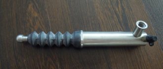
- vacuum brake booster;
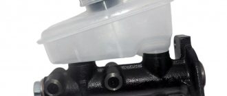
- master brake cylinder;
- brake system expansion tank;
- working (wheel) brake cylinders. Repairing the brake wheel cylinder is not a prerequisite when repairing the master brake cylinder;
- pipelines and hoses for moving brake fluid.
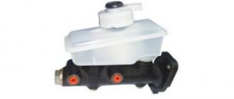
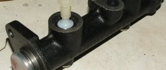
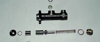
The main brake cylinder contains two pistons for the brake circuits, return springs and o-rings. Those. The task of the master brake cylinder, after pressing the brake pedal, is to evenly distribute the brake fluid along the circuits for its further transfer to the working brake cylinders of the wheels.
With a working brake system, the pressure in both circuits should be the same. If brake fluid leaks from one circuit, the second (primary or secondary) will provide braking to the vehicle.
Diagnostics of the main brake cylinder
Brake master cylinder repair - video
Before we look at the methods for diagnosing and repairing the master brake cylinder, a note. In cases where, for some reason, you carry out, for example, the front or rear brake cylinder, all diagnostic procedures begin with checking the GTZ.
The main malfunction of the master cylinder is the uneven distribution of brake fluid along the circuits. For example, due to a brake fluid leak, or. Considering that each circuit is responsible for its own pair of wheels, a drop in pressure in one circuit is not a momentary tragedy.
In any case, the second circuit will work, and the second pair of wheels will slow down the car. Naturally, braking efficiency will decrease. This in no way means that the car can be operated normally with a faulty turbocharger. It is not recommended to put off repairing the head brake cylinder.
Methods for diagnosing GTZ
- indications of control devices in the cabin - the brake system malfunction warning lamp indicator will light up;
- by visual inspection, check the master cylinder body for brake fluid leaks, especially at the junction of the pipelines with the circuit outlets;
- visually check for mechanical damage (cracks) in the GTZ housing;
- measuring the pressure level in the circuits: pressure gauges are connected to the openings of the circuits and the pressure is measured. You should compare the obtained figures with the control ones, which are given in the repair and operation manual for your car.
That is, you will immediately see which circuit has failed.
How to repair a brake cylinder
After the external inspection, we begin disassembling the GTZ. It should be remembered that such a diagnostic test as checking the GTZ for leaks cannot be carried out in a garage. For this you need a special stand.
When starting to disassemble the GTZ, wash all its parts with alcohol. Without exception, all rekhino-technical products are replaced with new ones. To do this, we offer an incredible number of repair kits for each brand of car at your service. When repairing brakes, you should not be guided by the principle: “it seems fine, it will still work.”
If, as a result of disassembly, you see that the rubber products (gaskets) have swollen, then most likely the reason for this is either unsuitable (poor quality) or the fact that it has become unusable due to severe contamination.
The main requirement for the GTZ mirror and pistons is the absence of mechanical damage, scratches, and scuffing. We have already talked about replacing the piston units.
You should absolutely not try to repair the GTZ pressure regulator. It changes as a set, since all parameters are set by the manufacturer.
Important! If you are going to do a complete replacement of the main brake cylinder or dismantle it, do not forget to pump out the brake fluid from the distribution tank and plug the brake system pipes. And don't forget that after repair work or replacement UNW? it is necessary to perform .
Not the most economical repair option is to completely replace the master brake cylinder with a new one. In this case, you need to proceed from the calculation of the costs of repair work and the purchase of components and repair kits and the cost of a new gas turbine engine.
Good luck with repairing your car's brake system.
Symptoms of a GTZ malfunction
The GTZ, or master brake cylinder, is one of the most important elements of the braking system, since it is thanks to it that the car slows down after the driver presses the brake pedal.
Modern cars are usually equipped with two-section gas turbine engines, which form two circuits that operate independently. This system allows the brake system to remain operational even if one of the circuits fails or loses its seal.
The operation of the GTZ varies depending on the location of the drive. On front-wheel drive vehicles, the first circuit controls the operation of the front right and rear left brake pads, the second - the front left and rear right. On rear-wheel drive cars, the first circuit controls the operation of the front brake pads, and the second circuit controls the operation of the rear brake pads.
Bleeding the brakes
After repairing the GTZ or RTC, as well as replacing the fluid, brake hoses or pipes, the brakes need to be bled. The essence of the event is to remove air from the braking system. For this procedure you will need:
- 8 (10) mm key;
- silicone transparent tube according to the diameter of the fitting;
- capacity;
- brake fluid.
All classic Zhiguli models use DOT-3 or DOT-4 brake fluid. Its volume in the “penny” hydraulic drive system is 0.66 liters. It is more convenient to bleed the system with a partner.
You need to start pumping the brakes from the right rear wheel. The process consists of the following steps:
- We install the machine on an overpass or inspection hole.
- Unscrew the filler plug of the expansion tank and check the fluid level. If necessary, bring it to the mark on the tank.
If the brakes are pumped correctly and there is no air left in the system, the pedal should feel tight when pressed and braking should be effective.
Video: how to bleed the brake system on a “classic”
I have repeatedly had to bleed the brakes alone, because there is not always an assistant available, for example, if a breakdown occurred on the road. For such situations, I always carry an expansion tank cap with a valve from a tubeless tire in stock. To make such a simple device, just drill a hole in the lid and insert a valve into it. When it becomes necessary to bleed the brakes, I screw this cap onto the reservoir. Using a piece of hose, I connect the valve to the spare wheel, having first unscrewed the valve valve from it. This creates pressure in the tank. Then I bleed the brakes according to the above scheme, ensuring that all air leaves the system, not forgetting to control the fluid level. I bleed the clutch in a similar way.
If there is a problem with the master brake cylinder, as evidenced by characteristic signs, the part needs to be diagnosed and subsequently repaired. If the unit has severe wear, then the problem can only be solved by completely replacing it. To carry out repair work, it is not necessary to visit a service station. It is enough to prepare the necessary list of tools and materials, read the step-by-step instructions and follow them during the work.
voice
Article rating
Where is the brake fluid located in the LADA Kalina?
This fluid completely fills the brake system: brake cylinders (main and working), brake hoses, pipes and reservoir. Its function is to transfer force from the brake pedal to the brake wheel cylinders. When the driver presses the brake pedal, the rod displaces the piston in the Kalina master brake cylinder, which presses on the fluid in the brake system. The fluid is incompressible, so it drives the pistons in the working cylinders, which press the mechanism pads against the brake discs and drums.
Working brake system: 1 — brake mechanism of the front left wheel; 2, 6, 12, 17 — brake hoses; 3, 7, 11, 18 — brake pipes; 4 — main brake cylinder; 5 — brake mechanism of the front right wheel; 8 — reservoir of the main brake cylinder; 9 — vacuum booster; 10 — brake pedal; 13 — brake mechanism of the rear right wheel; 14 — fluid pressure regulator in the brake mechanisms of the rear wheels; 15 — lever for regulating the fluid pressure in the brake mechanisms of the rear wheels; 16 — brake mechanism of the rear left wheel Note. Some cars are equipped with a braking system with ABS (anti-lock braking system).
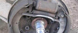
Brake mechanism of the rear wheel of VAZ 2101, 2102
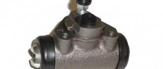
The rear wheel brake is drum type, with self-aligning pads. Brake pads 3 with linings 7 (see Fig. Rear wheel brake mechanism), wheel cylinder 1 and other parts are mounted on the brake shield, which is attached to the flange of the rear axle beam. A package of plates is attached to the bottom of the shield with two rivets, one of which is a support for the lower ends of the brake pads. To regulate the gap between the shoes and the drum, eccentrics 8 are used, on which the shoes rest under the action of tension springs 5 and 10.
1 – wheel cylinder; 2 – lever for manual drive of the pads; 3 – brake pad; 4 – cup and support post of the pads; 5 – parking brake drive cable with sheath; 6 – lower tension spring; 7 – friction lining; 8 – eccentric for adjusting the gap between the block and the drum; 9 – spacer bar; 10 – upper tension spring
In the housing 4 (see Fig. Wheel cylinder parts) of the wheel cylinder, there are two pistons 2, which are expanded by a spring 7 with support cups 5. The same spring presses the seals 3 to the end of the pistons.
Helpful information:
You can get professional advice when selecting a product and detailed information on all your questions by calling (calls within Russia are free).
Let's find out what could be causing your brake master cylinder to fail. First of all, its breakdown occurs due to the fact that the brake fluid is unevenly distributed inside the mechanism.
The cylinder itself consists of two working sections, each of which is responsible for braking one of the front wheels, as well as the rear one, located on the opposite side. You should know that in rear-wheel drive cars the picture is completely different: the sections are responsible for the operation of the brakes, which are located along the axes.
The work of the GTZ itself begins from the moment the pedal is pressed. If a vacuum booster is provided in the design of the car, then the brake cylinder contains 3 chambers, one of which converts pressing the brake into pressure, which makes it lighter. By pressing the pedal, a certain load is transferred to the piston section, which forces the brake fluid to press on the caliper. This, in turn, compresses the brake discs through the pads.
General information
Figure 1 — Steering parts from the vehicle interior:
- steering wheel
- upper steering shaft facing casing assembly
- M8 nut
- steering shaft assembly
- bolt M8x35
- washer 8
- M8 nut
- horn switch
- screw
- ring sealing
- screw 4.3x12.7
- lower steering shaft facing casing
- screw M5x20
- washer 5
- self-tapping screw
The steering is injury-proof, with a height-adjustable steering column, with a damping element on the steering wheel 1, Figure 1, and a rack and pinion steering mechanism.
Figure 2 — Power steering shaft assembly
An electric power amplifier is installed on the steering shaft, Figure 2, which reduces the force on the steering wheel.
Figure 3 — Steering mechanism parts:
- steering gear housing assembly
- right protective cap
- cover slats
- cover clamp
- plate
- locking plate
- steering linkage bolt
- stop insert
- rack stop
- ring sealing
- retaining ring
- spring
- screw
- nut plug
- gear boot
- bolt
- washer
- gear oil seal
- crankcase cover
- ring sealing
- separator assembly
- gear assembly
- steering rack
- left protective cap
- steering linkage support
- rod support bracket
In the lugs of the crankcase 1, Figure 3, of the steering mechanism, a drive gear 22 is installed on roller and ball bearings, which is meshed with a rack 23. The rack is pressed against the gear by a spring 12 through a metal-ceramic stop 9, which is sealed in the crankcase with a rubber ring 10. The spring rests against nut 13 with a locking ring 11, which creates resistance to unscrewing the nut.
There are marks on the steering gear housing and on the boot for correct assembly of the steering mechanism.
A protective cap 24 is put on the steering gear housing 1 on the left side, and a pipe with a longitudinal groove is pressed onto the right side. Through the groove of the pipe and the holes of the protective cover 3, bolts 7 pass, securing the steering linkages to the rack 23. The bolts pass through rubber-metal hinges pressed into the heads of the linkage tips. The bolts are secured with a locking plate 6.
The steering shaft 4, Figure 1, is connected to the drive gear 22, Figure 3.
The upper part of the shaft rests on a radial ball bearing. At the upper end of shaft 4, Figure 1, on splines, through a damping element, steering wheel 1 is secured with nut 9.
Figure 4 - Steering parts from the engine compartment of the car:
- right steering gear mounting bracket
- right support
- washer 8
- M8 nut
- bracket
- M6 nut
- washer 6
- protective casing
- steering mechanism
- shaft seal
- left steering gear mounting bracket
- steering gear support left
The steering drive consists of two horizontal rods and rotary arms of telescopic front suspension struts. The length of each rod is changed by a tubular rod, which is screwed onto the inner tip of the rod with one end, and screwed into the outer tip with the other and tightened with a bolt. The head of the outer tip contains the ball joint parts. The steering arms are welded to the front suspension struts.
About checking the GTZ
Malfunctions of the master cylinder may require repair or complete replacement. It is recommended to start checking the brake cylinder with an external inspection. It is necessary to carefully check it for external defects and leakage of brake fluid. After a visual inspection, you need to check the operation of the brake pedal. To do this, you need to press on it and make sure that it does not jam or fall through.
As for the master cylinder, it can not only wear out, but also become rusty from the inside over time. This often happens due to the fact that the brake fluid contains oxygen and water in certain quantities.
Self-replacement of the GTZ on Lada Kalina
The need to replace the brake master cylinder (MBC) arises when characteristic signs of a malfunction occur. Braking becomes ineffective, the pads are not fully extended, the drums and discs heat up, the pedal sinks or braking occurs only at the end of the pedal stroke.
If you experience any of the above, most likely the GTZ has failed. There is nothing terrible about this, since replacing the master brake cylinder is far from the most difficult task, and almost anyone can do it.
To work you need to have:
- New GTZ;
- Key "13" + head "13" with ratchet, cardan and extension;
- WD-40 (preferably), container for TJ;
- Straight arms and some free time.
Failure of the gas turbine engine and its replacement
One of the common reasons why the brake master cylinder fails is its depressurization. In practice, this is noticeable to the naked eye: the brake cylinder will constantly leak, leaving a characteristic mark and a specific smell. The level of brake fluid in the reservoir will continuously decrease. All these signs indicate the need to repair the gas turbine engine and prevent irreparable consequences.
Depressurization of the brake cylinder
is a good reason to replace it with a new mechanism. Malfunctions of the master brake cylinder such as damage and severe wear of the piston seals, inlet collar, piston return spring, as well as scuffing and severe wear of the mechanism mirror indicate mandatory repair or complete replacement of the turbocharger.
Your life and safety depend on the proper operation of the braking system. Therefore, when the above symptoms appear, it is necessary to urgently eliminate the malfunction so that there is no sudden brake failure on the road.
How to replace the GTZ on a Lada Kalina - step-by-step instructions
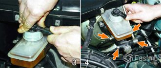
- First of all, take a syringe and pump out the brake fluid from the reservoir.
- We remove the terminals from the battery, we will remove it.
- Next, we disconnect the connector from the hood end switch, it is marked with a red arrow, the adsorber power supply is marked with a blue arrow, the fuel injection system is marked with a yellow arrow, and the mass air flow sensor is marked with a green arrow.
- Now you can remove the battery; in principle, nothing else should interfere. We treat with penetrating liquid (VD-shkoy) the nuts securing the GTZ to the vacuum brake booster (VUT), as well as the nuts of the brake pipes.
- Loosen the brake pipe nuts, and then drain the remaining brake fluid from the reservoir into a container prepared in advance.
- Using a key set to “13”, unscrew the two nuts of the brake pipes, with your hand, holding the engravers that are under them, pull the GTZ towards you, rocking it slightly. Small difficulties may arise here, since due to the vacuum that forms at this moment, it is not possible to remove it immediately. To make this step easier, you can operate the brake pedal.
- We take the new master brake cylinder, put it in place, and fasten it with the same nuts on “13”, not forgetting about the engravers under the nuts.
- Next we screw the tubes. By the way, some recommend doing this before attaching the GTZ, but in my opinion this is not critical, everything is installed well anyway.
In general, we do the assembly, after which we pour new brake fluid into the reservoir and, of course, bleed the brakes.
Source
Replacing guides and their lubrication
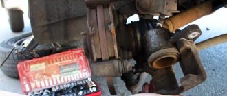
So, the first thing you need to do is remove the wheel bolts. Then lift the car with a jack, and finally unscrew the bolts and remove the front wheel. Then, using a flat-head screwdriver, bend the locking washers of the caliper bolts and unscrew the top bolt, as shown in the photo below.
We disengage the brake hose from the front strut, then use a screwdriver to push the cylinder down a little so that you can then tilt the bracket up without any problems.
And we fold it back, as mentioned above.
Now we have access to the upper caliper pin. With a slight movement of your hand, you can remove it by slightly pulling it to the side, overcoming the force of the boot.
Now that the finger is removed, thoroughly rinse it with cleaner and the boot, if it is intact. If necessary, take a new finger and boot.
Now you can apply new lubricant in small quantities so that excess does not get on the active working surfaces (brake pads and discs). For this procedure, I used MC1600 lubricant, which at one time was actively advertised in videos on YouTube and on third-party Internet sites. But I took it not because of advertising, but because of the lack of more or less normal lubricants in the store at the time of purchase.
According to the stated characteristics, the operating range of this lubricant is from -50 to 1000 °C. By the way, I didn’t expect that the cost of this bag is only 80 rubles. I thought it was several times more. Although, I can’t say that it’s particularly cheap! If you are constantly servicing the brake system while on the road, then of course it is more profitable to buy a large tube. If I'm not mistaken, it costs about 600 rubles per 100 grams.
This same bag will be enough to service the calipers of your Kalina for a year for sure!
You should not be overzealous, as excess may end up on the working surfaces, which will lead to a decrease in braking efficiency, and you will have to remove the residue with a cleaner or other degreaser.
Now you can put your finger in its place.
The lower finger changes in a similar way, so you are unlikely to encounter any difficulties when carrying out this repair! The effectiveness of the lubricant used can only be judged after long-term use, so we won’t rush to conclusions!