Engine repair is considered the most difficult thing in a car, because no other part contains such a huge number of interconnected elements. On the one hand, this is very convenient, because if one of them breaks down, there is no need to change the entire assembly; it is enough to simply replace the failed part; on the other hand, the more component elements, the more complex the device and the more difficult it is for those who I'm not very experienced in car repairs. However, with a strong desire, anything is possible, especially if your zeal is supported by theoretical knowledge, for example, in determining the tightening torque of the main and connecting rod bearings. If for now this phrase is a set of incomprehensible words for you, be sure to read this article before getting into the engine.
VAZ 2112 engine tightening torque
Tightening torque for the cylinder head of the VAZ 2112 engine:
- We tighten the M12XI.25 bolts for connecting the cylinder head in 4 steps:
- with force - 2 kgf/m;
- times torque - 7.1-8.7 kgf/m;
- once - turn it 90°;
- once - turn it 90°.
- M6 nuts attaching the engine cylinder head tire with a force of 0.2-0.47 kgf/m
Tightening torque of VAZ 2112 engine bolts:
- M6 bolts for attaching the housing of auxiliary devices with a force of -0.68-0.84 kgf/m;
- M6 bolts fastening the oil sump with a force of 0.52-0.84 kgf/m;
- Nagel M6 for connecting the Tasol pump - 0.78-0.82 kgf/m;
- Bolt M6 fastening the supply pipe of the coolant pump torque - 0.425-0.525 kgf/m
Tightening torque of the camshaft of the VAZ 2112 engine:
- M8 nut for the stud connecting the camshaft bearing housing with a force of 1.87-2.31 kgf/m;
- Bolt M10 fastening the camshaft pulley with a force of 6.88-8.5 kgf/m;
VAZ 2112 crankshaft tightening torque:
- Hardware M12x1.25 connection of the crankshaft pulley moment - 9.9-11.1 kgf/m
Tightening torque for VAZ 2112 main bearings:
- Bolts M10X1.25 for connecting the main bearing caps with a force of 6.97-8.61 kgf/m;
- M6 pin for attaching the oil receiver to the main bearing cover with a torque of 0.85-1.05 kgf/m
Tightening torque of VAZ 2112 engine connecting rods:
- Nuts M9x1 of the connecting rod cover bolts with a force of 4.42-5.46 kgf/m
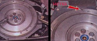
VAZ 2112 flywheel tightening torque:
- Bolts M10x1.25 for attaching the flywheel with a torque of 6.22-8.92 kgf/m
| VAZ engine tightening torque table | ||
| Name of propulsion devices and parts | Thread | VAZ 2112 engine tightening torque, kgf/m |
| Nut of the stud fastening the intake pipe and exhaust manifold | M8 | 2,13-2,63 |
| Tension roller connection nut | M10x1.25 | 3,4-4,2) |
| Nuts of studs for connecting the outlet pipe of the cooling jacket | M8 | 1,63-2,31 |
| Nut for connecting the exhaust pipe of the muffler | M8x1.25 | 2,13-2,63 |
| Nuts for fastening the flange of the additional silencer | M8x1.25 | 1,63-2,31 |
| Nut for attaching the clutch cable to the engine bracket | M12x1 | 1,5-2,0) |
| Bolts for connecting the front support bracket of the propulsion suspension | M10×1.25 | 3,3-5,5 |
| Nuts of bolts for attaching the front engine mount | M10 | 4,25-5,25 |
| Nuts of bolts connecting the left engine support | M10 | 4,25-5,25 |
| Nuts for fastening the left engine mount bracket | M10 | 3,25-5,25 |
| Bolts for attaching the rear suspension support for the driver | M10×1.25 | 2,8-3,47 |
| Nuts of bolts connecting the rear engine mount bracket | M12 | 6,2-10 |
| Bolts attaching the oil receiver to the pump | M6 | (0,7-0,84 |
| Oil pump bolts | M6 | 0,85-1,05 |
| Oil pump housing fastening bolts | M6 | 0,735-0,94 |
| Oil pump reduction throttle plug | M16×1.5 | 4,64-7,5 |
| Oil filter fitting | M20x1.5 | 3,8-8,9 |
| Oil pressure warning light sensor | M14x1.5 | 2,45-2,75 |
| Carburetor fastening nuts | M8 | 1,3-1,6 |
What are plain bearings
To better understand why engine bearings need to be tightened to a certain torque, let's take a look at the functions and purpose of these elements. Let's start with the fact that these sliding bearings interact with one of the most important parts of any internal combustion engine - the crankshaft. In short, the reciprocating motion of the piston in the cylinder is converted into rotational motion precisely thanks to the connecting rods and crankshaft. As a result, torque appears, which is ultimately transmitted to the wheels of the car.
The crankshaft rotates constantly, has a complex shape, experiences significant loads and is an expensive part. To maximize the service life of the element, connecting rod and main bearings are used in the crankshaft design. Taking into account the fact that the crankshaft rotates, as well as a number of other features, conditions are created for this part that minimize wear.
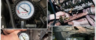
For the manufacture of liners, softer materials are used compared to those from which the crankshaft itself is made. The liners are also additionally coated with an anti-friction layer. Lubricant (motor oil) is supplied under pressure to the place where the liner is connected to the crankshaft journal. The specified pressure is provided by the oil pump of the engine lubrication system. In this case, it is especially important that there is the required clearance between the crankshaft journal and the plain bearing. The quality of lubrication of the rubbing pair, as well as the engine oil pressure in the engine lubrication system, will depend on the size of the gap. If the gap is increased, then the lubricant pressure decreases. As a result, rapid wear of the crankshaft journals occurs, and other loaded components in the internal combustion engine also suffer. In parallel with this, a knock appears in the engine.
Tightening torque of VAZ 2112 clutch threaded connections
Tightening torque of clutch bolts VAZ 2112:
- Bolts M12x1.25 fastening the clutch housing to the engine block with a force of 5.53-8.93 kgf/m;
- M8 bolt securing the clutch housing to the flywheel torque - 1.95-3.15 kgf/m;
- M6 bolts attaching the bottom cover to the clutch housing with a force of 0.4-0.6.
| List of devices and connections | Thread | Tightening torque of clutch parts VAZ 2112, kgf/m |
| Nut attaching the clutch housing to the engine block | M12x1.25 | 5,53-8,93 |
| Bolts for connecting the clutch release bearing guide bushing flange | M6 | 0,39-0,63 |
| Nut securing the clutch housing to the gearbox | M8 | 1,6-2,6) |
Maintenance
The actual life of the internal combustion engine is still unknown due to the short service life of the first cars that rolled off the assembly line in 2016. However, to increase it, engine 21179 should be serviced according to the regulations below:
- 10,000 km means changing the filter/oil;
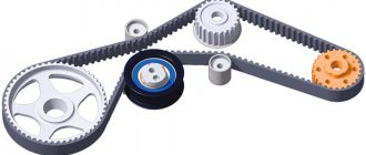
- twice as long, the alternator belt runs 30,000 km;
- after 45,000 km, change hoses/fittings and antifreeze;
- spark plugs and batteries are enough for 60,000 km;
- About 180,000 the original timing belt passes.
For 2022, the internal combustion engine device is considered the most advanced in the AvtoVAZ manufacturer’s line. In practice, his project had been considered since 2006, but was constantly postponed until the technical, economic and market situation in the Russian Federation finally developed favorably. That is, AvtoVAZ in this project prioritized the power output of the engine, and not economical fuel consumption, as was usually the case before.
VAZ 2112 gearbox tightening torque
| List of devices and parts | Thread | Tightening torque of VAZ 2112 gearbox parts, kgf/m |
| Conical screw for attaching the drive rod joint | M8 | 1,66-2,05 |
| Gear selection mechanism connection bolts | M6 | 0,65-1,05 |
| Gear shift lever housing mounting bolts | M8 | 1,6-2,6 |
| Nut for connecting the drive rod clamp and jet rod | M8 | 1,6-2,6 |
| Nut of the rear end of the primary and secondary shafts | M20x1.5 | 12,3-15,2 |
| Reversing light switch | M14x1.5 | 2,9-4,6 |
| Bolt attaching the forks to the rod | M6 | 1,2-1,9 |
| Differential driven gear fastening bolt | M10x1.25 | 6 5-8,4 |
| Speedometer drive housing connection nut | M6 | 0,45-0,73 |
| Bolt for attaching the gear selector lever axis | M6 | 1,2-1,9) |
| Nuts for attaching the rear cover to the gearbox housing | M8 | 1,6-2,6 |
| Reverse fork clamp plug | Ml 6×1.5 | 2,89-4,6 |
| Conical screw for fastening the gear selector rod lever | M8 | 2,89-3,57 |
| Clutch housing and gearbox connection bolts | M8 | 1,6-2,6 |
| Drain plug | M22x1.5 | 2,9-4,7 |
When the throttle cable needs to be replaced
How to determine the moment when the VAZ-2110 throttle cable requires replacement? Experts recommend paying attention to the following points in the operation of this vehicle part:
- it is not possible to regulate the throttle valve drive;
- when pressing the accelerator pedal, the damper cannot open and close fully;
- the metal part of the cable began to “shag” (this can be seen visually when checking the internal parts of the car);
- When the throttle valve is operating, the gas cable constantly gets stuck.
If you find one of these problems in the operation of your vehicle, then you need to immediately buy a new throttle cable and replace it.
Tightening torque of threaded connections of the front suspension of VAZ 2112
VAZ 2112 hub nut tightening torque:
- Nut M20xl.5 for rear wheel hub bearings torque - 19-23 kgf/m;
- Nuts M20xl.5 of the front wheel hub bearings with a force of 23-25.2 kgf/m.
| Name of devices and connections | Thread | Tightening torque of threaded connections VAZ 2112, kgf/m |
| Nut for attaching the upper support to the body | M8 | 2-2,47 |
| Nut connecting the ball pin to the lever | M12XI.25 | (6,8-8,4 |
| Nut of the eccentric bolt fastening the telescopic strut to the steering knuckle | М12Х1.25 | 7,9-9,8 |
| Bolts for attaching the telescopic strut to the steering knuckle | M!2xl,25 | 7,9-9,8 |
| Bolts and nuts connecting the suspension arm to the body | M 12×1.25 | 7,9-9,8 |
| Nut for attaching the guy wire | M16x 1.25 | 16,3- 18 |
| Bolts and nuts securing the stabilizer bar to the arm | M10xl,25 | 4,29-5,3 |
| Nut connecting the stabilizer bar to the body | M8 | 1,32-1,63 |
| Bolts for fastening the brace bracket to the body | M10x1.25 | 4,3-5,3 |
| Nut for fastening the telescopic rod rod to the upper support | M14x1.5 | 6,72-8,29 |
| Bolt securing the ball joint to the steering knuckle | M8 | M10×1.25 |
| Wheel bolt | M12xl,25 | 6,65-9,45 |
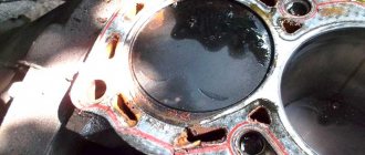
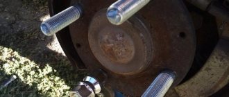
Procedure for installation and dismantling
The cylinder block is the basis for mounting the head, which is held on by 10 screws. Unscrewing is carried out with a special socket wrench - “ten”.
The photo shows the correct folding order:
- Top right corner.
- Bottom right corner.
- Top left corner.
- Bottom left corner.
- Top second from left.
- Top second from the right.
- Second bottom from the right.
- Second bottom from the left.
- Top in the middle.
- Bottom in the middle.
By strictly observing this sequence, you can avoid deformation of bolts and threads, as well as other unpleasant moments.
The design of the unit is quite complex, although at first glance it seems primitive.
The head is attached with bolts or studs to the block and closes the cylinders on top. The seating area of the upper element is very large, therefore the correct sequence of tightening the threaded connections with a specific force is very important. Previously, older car models had cast iron elements of this unit, which were easier to work with. Nowadays, softer, lighter and more ductile aluminum is predominantly used, when working with which it is very easy to damage a cylinder. Cast iron is also much more resistant to heat shrinkage and deformation, which does not yet allow us to completely abandon it.
The standard screw size in the model we are considering is 93 mm. If even one stretches even a couple of millimeters, it must be replaced immediately.
The installation sequence differs from the above order and is shown in the photo:
- Middle bottom.
- Upper lower.
- Bottom second from left.
- Bottom second from right.
- Top second from the right.
- Top second from left.
- Bottom corner left.
- Top corner left.
- Bottom corner right.
- Top corner right.
Tension torque standards:
- The force at the first stage is 20 N*m.
- Each element should be turned to the right by 90 degrees.
- After 20 minutes of waiting, you need to turn it another 90°.
The initial effort is small. But from the third stage the work becomes more difficult, so a lever is used. If you have any difficulties with the stretching process, watch the video tutorial in which everything is shown and explained in detail.
Installing a cylinder head under a turbine on an internal combustion engine is not much different from the option discussed above, but in case of inconsistencies or other problems, it is better to seek advice or help from qualified specialists.
Tightening torque for rear suspension threaded connections
| Name of devices and parts | Thread | Tightening torque of threaded connections VAZ 2112, kgf/m |
| Nut for attaching the lower end of the shock absorber | M12x1.25 | 6,8-8,4 |
| Rear suspension arm fastening nuts | M12x1.25 | 6,8-8,4 |
| Nuts for attaching suspension arm brackets | M10x1.25 | 2,8-3,46 |
| Nut for connecting the upper end of the shock absorber | M10x1.25 | 5,1-6,3 |
Process Features
Each engine has its own torque, as does the pin tightening pattern. The indicator of this moment is influenced not only by the type of engine, but also by other factors that you need to know if you decide to carry out this procedure yourself.
- how well the pin holes are lubricated and the very condition of the elements;
- the quality of the bolts plays a big role - bad or old ones may not survive tightening;
- if the thread or the pin itself is deformed, it is better not to tighten it. Because after a short period of time, all elements that do not meet operating standards will fail.
Steering torque
| List of mechanisms and connections | Thread | Tightening torque of threaded connections VAZ 2112, kgf/m |
| Steering gear housing mounting nuts | M8 | 1,53-1,9 |
| Nut for connecting the steering shaft bracket | M8 | 1,53-1,9 |
| Steering shaft bracket attachment bolts | M6 | Twist until the head comes off |
| Bolt securing the steering shaft to the gear | M8 | 2,3-2,8 |
| Steering wheel fastening nut | M16x1.5 | 3,2-5,2 |
| Tie rod end bolt | M10 | 1,95-3,15 |
| Ball pin connection nut | M12x1.25 | 2,76-3,41 |
| Bolt for attaching the steering linkage to the rack | MIOxl | 7,13-8,6 |
| Steering gear bearing nut | M38x1.5 | 4,6-5,6 |
Video
The video (Auto_Remont channel) describes in detail the process of installing and assembling the cylinder head on a VAZ 2112.
VAZ 2110 engine assembly
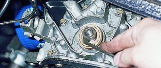
Assemble the engine on a VAZ 2110 car as follows. Place a clean cylinder block on the stand and screw the missing studs into the cylinder block. Install the generator mounting bracket and secure it with two bolts. Lubricate the bearing shells and thrust half rings of the crankshaft, as well as the pistons and oil seals with engine oil. When assembling the engine after repair, install new crankshaft oil seals. Install liners with a groove in the 1st, 2nd, 4th and 5th seats of the cylinder block, and liners without a groove in the 3rd seat of the cylinder block and in the main bearing caps. Place the crankshaft in the main bearings and insert the thrust half-rings into the seat of the middle main bearing (Fig. 2-18).
Warning
The half rings must have their grooves facing the thrust surfaces of the crankshaft (an antifriction layer is applied to the surface of the half ring on the side of the grooves).
Tightening torque of connections of the brake system of VAZ 2112
| List of mechanisms and connections | Thread | Tightening torque of threaded connections VAZ 2112, kgf/m |
| Bolts attaching the brake cylinder to the caliper | Ml 2×1.25 | 11,72-15,3 |
| Bolt connecting the guide pin to the cylinder | M8 | 3,16-3,88 |
| Bolts securing the brake to the steering knuckle | M10x1.25 | 2,97-3,67 |
| Bolts attaching the rear brake to the axle | M10x1.25 | 3,5-4,35 |
| Nuts securing the vacuum booster bracket to the bracket booster | M8 | 1-1,6 |
| Nuts connecting the master cylinder to the vacuum booster | M10 | 2,7 — 3 ,3 |
| Nuts for attaching the vacuum booster to the bracket booster | M10 | 2,7—3,3 |
| Brake pipe connection nuts | M10 | 1,5-1,9 |
| Front brake flexible hose end | M10x1.25 | 3,0-3,4 |
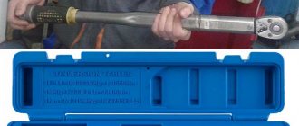
Homemade torque wrench (as a last resort)
Homemade.
It’s designed roughly like this, but you won’t be able to tighten it properly with such a device! As a last resort, you can use a tool that you can assemble with your own hands.
The following two tabs change content below.
- About the author:
- Latest articles:
I'm just sick of cars. I try to study in detail every car I have owned. I enjoy driving at night on city streets. I try to do my own repairs on my cars!
Similar materials
Tags: VAZ-2112Questions VAZ-2112
Procedure for installation and dismantling
The cylinder block is the basis for mounting the head, which is held on by 10 screws. Unscrewing is carried out with a special socket wrench - “ten”. The photo shows the correct folding order:
- Top right corner.
- Bottom right corner.
- Top left corner.
- Bottom left corner.
- Top second from left.
- Top second from the right.
- Second bottom from the right.
- Second bottom from the left.
- Top in the middle.
- Bottom in the middle.
By strictly observing this sequence, you can avoid deformation of bolts and threads, as well as other unpleasant moments. The design of the unit is quite complex, although at first glance it seems primitive.
The head is bolted or pinned to the block and closes the cylinders on top. The seating area of the upper element is very large, therefore the correct sequence of tightening the threaded connections with a specific force is very important. Previously, older car models had cast iron elements of this unit, which were easier to work with.
Nowadays, softer, lighter and more ductile aluminum is predominantly used, when working with which it is very easy to damage a cylinder. Cast iron is also much more resistant to heat shrinkage and deformation, which does not yet allow us to completely abandon it.
The standard screw size in the model we are considering is 93 mm. If even one stretches even a couple of millimeters, it must be replaced immediately. The installation sequence differs from the above order and is shown in the photo:
- Middle bottom.
- Upper lower.
- Bottom second from left.
- Bottom second from right.
- Top second from the right.
- Top second from left.
- Bottom corner left.
- Top corner left.
- Bottom corner right.
- Top corner right.
Tension torque standards:
- The force at the first stage is 20 N*m.
- Each element should be turned to the right by 90 degrees.
- After 20 minutes of waiting, you need to turn it another 90°.