The Russian automaker VAZ produces a sufficient range of cars. Brand models are in great demand among domestic car enthusiasts and in the CIS countries. The popularity is due to the moderate cost and cheap repair of cars. However, problems happen with any vehicle and the plant’s products are no exception. Error codes for the VAZ 2114 injector can guide the motorist regarding the area of the breakdown and help in troubleshooting the problems.
About the VAZ 2114 system
As you know, the VAZ 2114 is practically a copy of the VAZ 2109, but only subjected to restyling. The VAZ 2114 inherited almost all the parameters of the “nine” with the exception of one; the fourteenth model was always produced only with injection engines, but the “9” started off the assembly line with carburetor engines.
Everyone knows about the reliability and unpretentiousness of an injection engine compared to carburetor counterparts. Currently, there are fewer and fewer cars with carburetors, and the production of such cars is completely prohibited due to European standards.
The VAZ 2114 injection system is equipped with a huge number of different sensors that are involved in the operation of the engine. Sometimes it happens that one of the sensors may fail and then the operation of the entire internal combustion engine becomes incorrect, the “CheckEngine” lamp lights up, fuel consumption increases and much more. To quickly and accurately identify vehicle malfunction problems, you need to know all the signs of sensor malfunctions to identify the culprit of the problem.
This article talks about the sensors of the VAZ 2114 engine management system, namely, each of the sensors is described in detail, where it is located and what function it is responsible for. After reading this article, you will easily learn how to identify failed sensors and also know their location.
Reverse Controller Replacement Guide
How to replace the reverse sensor:
- First, the car should be driven into a pit or overpass. Raise the parking brake lever and set the gear selector to first speed. This will prevent the machine from possibly rolling away.
- Next, you need to remove the protective cap from the contacts of the device; you need to disconnect the contacts from the RZH. When dismantling the gearbox regulator, some of the working fluid will come out, so you should place a container to collect the oil under its installation site.
- After this, you can begin to remove the device. Usually it can be removed by unscrewing it by hand, but sometimes, if the regulator is installed very tightly, it is advisable to use a wrench or socket. The head size should be 22. If the regulator is very stuck to the seat, then it may not be possible to unscrew it with the head. Try spraying the installation area with WD-40 and wait a few minutes. If this does not help, then you will have to use a chisel and hammer to remove it, but be careful not to damage the gearbox housing.
- After the old RZH is removed, you will need to install a new regulator in its place.
- If, during replacement, some fluid gets onto the transmission housing, it must be removed using a dry rag. Also clean the location where the regulator is installed, as contamination may cause it to malfunction or become inoperable.
- Reinstall the connection connector and the protective cap. If, during the replacement, a significant amount of transmission fluid comes out of the gearbox, then lubricant must be added to the box. Please note that the oil must be fresh, and not used oil that came out of the gearbox. If you notice that the drained fluid is too dirty and contains wear products, then it makes sense to think about replacing it.
Photo gallery “Replacing RZH”
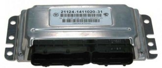
Electronic engine control unit (ECU)
The electronic engine control unit is the brain center of the entire car. All sensors installed in the car are connected specifically to this unit. All necessary calculations and consequences are calculated in the ECU. The engine control unit corrects all its operation. Located at the bottom of the VAZ 2114 dashboard at the feet of the front passenger.
Symptoms of ECU malfunction:
Signs of an ECU malfunction include all of the following signs of sensor malfunctions. After all, each sensor transmits readings to the ECU, and it, in turn, must process them, but it happens that for some reason these processes may not be processed in the ECU. In case of such problems, the ECU must be repaired, the tracks must be soldered, or failed radio components must be replaced.
Diagnostics
There are two ways to set error codes for VAZ 2114 injector 8 valves. However, each method has unique advantages and disadvantages.
Self-diagnosis of VAZ 2114: error codes and their interpretation
The self-diagnosis method does not require the driver to have complex instruments or additional units. To complete the procedure, the car itself is enough.
The standard sequence of actions looks like this.
- Press the odometer reset button.
- Turn the ignition key to position No. 1 (turn on the on-board electrics).
- Release the mileage reset button. After this, the instrument arrows will make a full revolution and return to their place.
- Press the reset button a second time and release. The command displays the firmware version indicator.
- Repeat step No. 4 - this will display error codes on the on-board computer.
If the sequence of actions is performed correctly, all indicators will light up and the display will show a two-digit fault code.
Note!
A failure signal may be a lack of response from the indicator. In this case, it is necessary to check the circuit coming from the device.
The most common error codes for the VAZ 2114 panel, occurring in 90% of cases:
- 1 – microprocessor failure, flashing required;
- 2 – error code 2 VAZ 2114 indicates that there is an interruption or disruption in the wiring of the float sensor inside the gas tank;
- 4 – electrical wiring short circuit, voltage limit exceeded;
- 8 – error code 8 on the VAZ 2114 indicates a drop in voltage in the network, the battery may have run out;
- 12 – in the VAZ 2114, error code 12 indicates that the warning lamp is not functioning properly;
- 13 – open circuit of the oxygen sensor;
- 14 – error code 14 on the VAZ 2114 warns the driver that the engine has overheated or the antifreeze temperature sensor has shorted;
- 15 – short circuit or DTOZh has failed;
- 16 – exceeding the permissible voltage limit of the on-board network;
- 17 – BS voltage has dropped critically, battery discharge is allowed;
- 19 – DPKV does not respond or there is a short circuit on the line;
- 21-22 – incorrect response of the TPS, possible short circuit or wiring break;
- 23/25 – short circuit of the throttle position sensor;
- 24 – speedometer failure, power cords may be broken;
- 27/28 – CO sensor worn out or broken;
- 33/34 – problems with the mass air flow sensor, possible power loss or short circuit;
- 35 – IAC sensor has failed, can only be treated by complete replacement;
- 41 – incorrect phase distribution covered or shorted;
- 42 – the circuit has failed or the wires of the electronic ignition unit have been broken;
- 43 – mixture detonation sensor is faulty;
- 44/45 – there is a violation of the fuel supply to the engine, the system may trip, jerks appear during acceleration, and it picks up speed poorly;
- 51 – ROM is acting up;
- 52 – similar for RAM;
- 53 – potentiometer failure;
- 54 – break in wiring for octane corrector;
- 55 – excessive leanness of the mixture during acceleration;
- 61 – interruptions in the operation of the lambda probe.
In some cases, errors may be superimposed on each other if the failure is similar. For example, if errors 1 and 4 intersect, the panel will indicate "5".
It is important to know that after viewing, VAZ 2114/2115 error codes do not disappear on their own after repairs are performed. They need to be forced reset. To complete the work you will need a simple sequence of actions:
- turn on the car ignition;
- remove the terminals from the battery;
- wait 20-30 seconds;
- return the clamps to their place.
This also needs to be done if you are planning a trip to a service station. Having discovered the instructions from the on-board computer, the technicians will correct these problems, which will definitely be more expensive.
The disadvantages of an independent procedure include the low accuracy of the data. On-board diagnostics only show the general direction vector where the fault should be looked for.
Check using diagnostic equipment
You can identify error codes for VAZ 2115 and 2114 using a laptop with a special program. The tool is connected to the vehicle's test socket through a set of adapters. The wizard configures the software, and after diagnostics, one or more faults will be displayed on the computer screen in the form of a five-digit code.
The first part is the letter:
- B – damage to body panels;
- C – chassis or suspension malfunction;
- P – electrical, engine or transmission disorder;
- U – damage to the terminal for information exchange.
The second part is a single digit:
- 0 – typical indicator according to the SAE standard;
- 1/2 – conveyor failure code;
- 3 – reserve.
The next element is the breakdown group indicator:
- 1/2 – defect in the fuel/air line;
- 3 – ignition and related elements;
- 4 – catalyst;
- 5 – XO of the power plant;
- 6 – ECM and related wiring;
- 7/8 – transmission blocks.
The final two numbers point directly to the problem itself.
Mass air flow sensor (MAF)
The mass air flow sensor is located in the engine compartment of the VAZ 2114 and is one of the most recognizable car sensors. The mass air flow sensor is attached with two bolts to the air filter box. The mass air flow sensor is responsible for counting the air intake from the engine and transmits the readings to the above-mentioned ECU. The mass air flow sensor is directly related to the formation of the air-fuel mixture.
Signs of a DMRV malfunction:
- Deterioration of car dynamics;
- Increased fuel consumption;
- Floating speed at XX;
- When starting the internal combustion engine, you have to turn the starter for a long time;
Diagnostics using special equipment
If you resort to a verification method using special equipment, you will need a computer on which diagnostic software is pre-installed.
The necessary software (programs) is downloaded from the Internet:
To connect to the diagnostic output, you will need a wire with an adapter. One end of the cable is connected to the header, and the other to the USB input on the computer or laptop.
For diagnostics, perform the following steps:
- A detailed inspection of the car is carried out. The car owner checks the availability of consumables. This can be brake fluid, engine and transmission oil, and antifreeze.
- The diagnostic output is searched for and a computer is connected to it. The ignition system in the car is first activated by turning the key in the lock to the appropriate position. The engine should not start. If there is a special scanner, then instead of a computer, this equipment is connected to the diagnostic connector.
- Then the diagnostic software is launched. Depending on the developer, the utility interface may differ. In many programs, when launched, graphs or technical parameters of the car with numbers appear.
- The car begins checking for errors; to do this, press the corresponding button in the program. At the end of testing, the utility displays error codes.
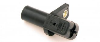
Crankshaft position sensor (CPS)
DPKV is installed near the timing belt, namely near the crankshaft gear. This sensor is responsible for counting the crankshaft revolutions from the generator belt pulley. DPKV is involved in the formation of the spark necessary to ignite the fuel mixture in the combustion chamber. If the crankshaft position sensor fails, the car engine will not start.
Signs of DPKV malfunction:
- The car's internal combustion engine does not start;
- Spontaneous stop of the internal combustion engine;
- Uneven operation at idle and high speeds;
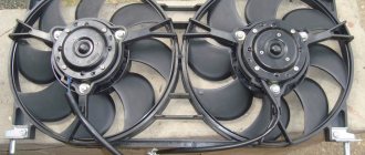
Coolant temperature sensor (DTOZH)
The coolant temperature sensor is installed in the thermostat housing and is used to turn the engine cooling fan on and off. It should be noted that turning on the fan is not the only task of this sensor. DTOZH adjusts the fuel mixture to maintain higher engine speeds when warming up, that is, if the coolant in the car is below operating temperature, the sensor will give readings about the enrichment of the fuel mixture to warm up the engine faster.
Signs of DTOZh malfunction:
- The cooling fan does not work;
- No warm-up speeds;
- The car does not start well;
- Increased fuel consumption;
Diagnostics using special equipment
If you resort to a verification method using special equipment, you will need a computer on which diagnostic software is pre-installed.
The necessary software (programs) is downloaded from the Internet:
To connect to the diagnostic output, you will need a wire with an adapter. One end of the cable is connected to the header, and the other to the USB input on the computer or laptop.
For diagnostics, perform the following steps:
- A detailed inspection of the car is carried out. The car owner checks the availability of consumables. This can be brake fluid, engine and transmission oil, and antifreeze.
- The diagnostic output is searched for and a computer is connected to it. The ignition system in the car is first activated by turning the key in the lock to the appropriate position. The engine should not start. If there is a special scanner, then instead of a computer, this equipment is connected to the diagnostic connector.
- Then the diagnostic software is launched. Depending on the developer, the utility interface may differ. In many programs, when launched, graphs or technical parameters of the car with numbers appear.
- The car begins checking for errors; to do this, press the corresponding button in the program. At the end of testing, the utility displays error codes.
Throttle Position Sensor (TPS)
The TPS is installed on the throttle itself and is a potentiometer. The sensor will transmit readings to the ECU about the position of the throttle valve. This type of sensor has an unreliable design and quite often fails. On newer VAZ 2114 models with an electronic gas pedal, there is no TPS.
Signs of a malfunction of the TPS:
- High engine speed when warming up;
- Jumps in engine speed;
- Increased fuel consumption;
- Not stable XX;
How to reset errors yourself
Video on how to reset the error code on a VAZ 2114, 2115
After checking the components and repairing, it is necessary to reset the errors. In principle, this can be done at any time, even without checking, if you want to make sure that it was not erroneous.
To reset the self-diagnosis codes of the on-board computer on the VAZ 2114 panel, after displaying the firmware version and the code itself, press the button again and hold for 4-5 seconds. As a result of resetting the error codes, “0” will be displayed on the VAZ 2114 injector.
Such a system for checking error codes is available not only on VAZ 2113, 2114, 2115, but also on models 2110, 2111, 2112, Priora and Kalina. The principle of checking and resetting errors is similar.
Source
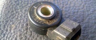
Knock sensor(DD)
The knock sensor is installed on the cylinder block between cylinders 2 and 3. The functions of the sensor are to detect detonation during engine operation and transmit the received signals to the ECU. The sensor is made on the principle of a piezo element and has a simple design.
Signs of DD malfunction:
- High fuel consumption;
- Vibrations during internal combustion engine operation;
- Jerks when moving;
Diagnostics using special equipment
1. Diagnostic connector
2. Connecting a wire with an adapter to the diagnostic socket
3. Connecting the wire to the computer
4. Launching software for testing
The diagnostic process using special equipment consists of checking the car using a laptop. To connect to the diagnostic connector you will need a cable with an adapter. Using this cable, we connect the computer to the connector via USB output. For testing you will also need software; the power of the computer used is not important. There are many versions of different testing programs on the Internet.
Diagnostics is performed as follows:
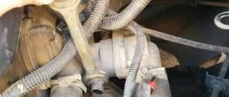
Oil pressure sensor (OPS)
The oil pressure sensor is located near the oil filler neck. The sensor serves as a signal to the driver about a decrease in oil pressure in the engine. When the pressure decreases, it sends a signal to the instrument panel and lights up the low oil pressure warning light.
Signs of DDM malfunction:
- Constant lighting of the oil pressure lamp;
- Oil leakage from the joint in the sensor;
Idle air control (IAC)
The IAC is installed on the throttle body of the car and serves to adjust the idle speed by opening and closing the air channels. This sensor is involved in the operation of the internal combustion engine only at idle. It is unreliable and often malfunctions. Subsequently, with the transition to the E-GAZ system, the idle air control was removed.
Signs of IAC malfunction:
- The internal combustion engine stalls at idle;
- High speed at idle;
- High fuel consumption;
We find and fix the problem
Signs of DMRV problems
So:
- The engine does not start;
- Unstable engine operation at idle;
- Engine idle speed is too high or too low;
- “Failures” during acceleration and poor vehicle dynamics;
- Fuel consumption is significantly exceeded.
Diagnostics
In addition to the above symptoms, a malfunction of the flow meter can be detected by the electronic control unit, namely its diagnostic system, which will issue a “CHECK” signal on the instrument panel. Unfortunately, without specialized diagnostic equipment with a 100% guarantee, it is impossible to identify a malfunction of the mass air flow sensor by reading error codes; you will have to contact a service station. Although, this is also controversial advice, since they will most likely offer you to identify the malfunction of the flow meter by replacing it with a known good device, but you can do this with your own hands without outside help. Let’s try to identify a flow meter breakdown in “field” conditions using four methods known to mankind. In general, we read carefully and remember. So, instructions:
The first method is the main one.
We disconnect the wire plug from the sensor and start the engine, the engine speed will rise to at least one and a half thousand per minute, and we’ll move off. If the car has acquired agility that is unusual for it, there is a malfunction of the sensor. Let me explain: the sensor is disabled, which means the ECU supplies the amount of gasoline according to the throttle position (emergency mode), without taking into account the signal from the flow meter.
When replacing the firmware in the ECU, no one will be able to say exactly what the idle speed setting is during emergency operation (method one). Therefore, this nuance is checked as follows: we slip a feeler gauge one millimeter thick under the throttle valve stop. After the speed rises, disconnect the sensor wire connector. The engine stalled - the firmware is to blame, or rather the idle speed adjustment in emergency mode.
The third method is the most accurate.
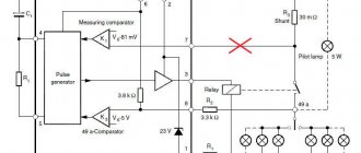
We turn the tester into DC voltage measurement mode and set the limit to two volts. We connect the probes to the yellow output wire - the plus probe and to the mass colored green wire - the minus probe, located relative to the windshield - the first and third, respectively.
Turn on the ignition, do not start the engine, take readings:
As a rule, the voltage of a working sensor is 0.996 – 1.01
Volt, but during wear it steadily increases:
- the sensor is in good condition at voltages from 1.01 to 1.02 V;
- slight wear: 1.02 – 1.03 V;
- decent mileage, will soon require replacement: 1.03 – 1.04 V;
- to be replaced at 1.04-1.05;
- It is prohibited to operate the sensor at a voltage of 1.05 Volts or higher.
Method number three
Method four, visual.
Using a curved screwdriver, remove the corrugated air duct going to the throttle assembly, and carefully inspect the internal surfaces of the air duct and sensor for the presence of condensate and oil; they should be dry and clean.
Using a ten key, unscrew the two screws and remove the sensitive element.
Checking the O-ring
As can be seen in the photo, on its front part there is a rubber sealing ring that prevents the leakage of foreign air into the intake manifold in addition to the sensor
Please note that when the integrity of the ring is destroyed, a small layer of dust forms on the sensor mesh. This is also one of the main reasons for “killing” the flow meter
In addition to the above methods, it is necessary to mention such factors as the lack of on-board power supply and unqualified maintenance (even innocent wiping of the working surfaces with a cotton swab can lead to damage to the unit). This unit is considered non-maintainable and non-repairable.
Phase sensor (PF)
The phase sensor is located:
- In 16-valve engines near the intake camshaft gear;
- In 8-valve engines from the end of the cylinder head near the mass air flow sensor;
Serves for phased fuel injection. It is a fairly reliable sensor that rarely fails. The design of the sensors for 8 and 16 valve engines is different and is not interchangeable.
Signs of DF malfunction:
- Increased fuel consumption;
- Engine vibrations;
Brake pedal sensor
The brake pedal sensor is installed on cars to turn on the brake lights (brake lights) when the car brakes. In cars with the E-GAZ system, the brake pedal sensor is also connected to the ECU and participates in the operation of the gas pedal to distribute the engine load more evenly.
Signs of malfunction:
- Gas pedal failure;
- Jerks when moving;
- Loss of car dynamics and power;
Is it possible to drive with error 8?
Operation of a machine with fault code 8 is not prohibited. But it can be inconvenient, since the battery can run out at any time. Then it will be impossible to start the car. Therefore, it is recommended that immediately after discovering an error, take measures to eliminate it. This is especially important in winter or before the onset of cold weather.
Content
In the VAZ 2114 car, the manufacturer installed an on-board computer, thanks to which you can find out in time about the presence of a malfunction and promptly eliminate it before the problem worsens. But on the display, errors are displayed in the form of numbers - special codes that require decoding, since by themselves they do not carry any meaning. Error codes for VAZ 2114 injector 8 valves: list.
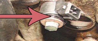
Speed sensor (DS)
The speed sensor is installed in the gearbox housing near the exhaust manifold. Designed to calculate the vehicle speed and adjust the speed when driving in neutral gear.
Signs of DS malfunction:
- Increased fuel consumption;
- Lack of travel speed XX;
- Dips when pressing the gas pedal sharply;
- Speedometer malfunction;
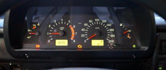
How to do a self-diagnosis
Error codes appear on the display of your on-board computer as a result of self-diagnosis. It is carried out according to the algorithm:
- On the dashboard, locate the odometer button. Press it and don't let go.
- Turn the ignition key to position 1 without releasing the button.
- Release the odometer button.
- While the computer is scanning, the arrows on the dashboard will twitch. This means you did everything right.
- Press the odometer button again to display the information on the on-board computer display. After the first press, the firmware numbers for your system will appear on the screen.
- Pressing the odometer button a second time will cause error codes to appear on the screen.
Most often, during self-diagnosis, you can see two-digit codes that are deciphered using a service passport.
Oxygen sensor (DC, lambda probe)
An oxygen sensor, also known as a lambda probe, is installed in the exhaust manifold and is designed to record exhaust carbon dioxide gases. In some car models that were produced after 2010. There are 2 oxygen sensors. Serves to adjust the air-fuel mixture based on carbon dioxide measurements.
Signs of DC malfunction:
- High fuel consumption;
- Loss of engine power;
- Difficult starting of the internal combustion engine;
Essential on-board computer error codes
Self-diagnosis, of course, will not give such a high-quality result as if you contacted a specialized service station. However, the first thing you need to check before leaving is whether there are any problems with your car at all. To do this you will have to perform a few simple steps:
- Once in your usual driver's seat, hold down the odometer button.
- It is necessary to turn the key in the ignition switch and lock it in the first position.
- After pressing the button, you will notice that the instrument panel arrows will begin to “go crazy” (run chaotically and on their own).
- By holding the button again and turning off the ignition, you will be presented with the computer firmware version.
- By clicking the button a third time (in one click), you will see the presence or absence of errors.
Odometer codes are universal, and they can indicate errors in vehicle operation without resorting to the on-board computer. The most typical VAZ-2114 error codes shown by the odometer:
- l 1 – this code indicates incorrect operation of the microprocessor;
- l 2 – inaccurate fuel level in the tank;
- l 4 – abnormally high mains voltage;
- l 8 – the voltage of the car’s electrical network is too low;
- l 13 – oxygen sensor does not function;
- l 14 – excessively high signal from the liquid cooling sensor;
- l 15 – liquid cooling sensor readings are too low;
- l 16 – unnaturally high voltage of the on-board network;
- l 17 – minimum voltage of the on-board network;
- l 19 – pay attention to the crankshaft;
- l 24 – malfunction in the speed sensor;
- l 41 – false phase sensor readings;
- l 51 – the permanent storage device is not working properly;
- l 52 – error in the operation of the random access memory device;
- l 53 – CO potentiometer refuses to work at all;
- l 61 – the lambda probe sensor is inoperative.
When looking for errors using the odometer, you should always remember that the computer is capable of summing the codes, which gives some inaccuracy. For example, if a car has errors 4 and 8, it can give you number 12. You should also remember that when checking in this way, all errors will be stored in the car’s memory, and this is a very irritating factor. To reset the indicators, you need to remove the battery terminals and after a few minutes put them back on.
Ignition module (IZ)
The ignition module is installed on 8-valve engines on a platform that is attached to the cylinder block. The 16-valve VAZ 2114 engines use individual ignition coils. The module is designed to generate a powerful high-voltage spark necessary to ignite the air-fuel mixture in the combustion chamber of a car. It has two coils each, of which is responsible for two cylinders. If one of the coils fails, 2 cylinders stop working at once.
Signs of malfunction of the MH:
- Several cylinders do not work (most often two);
- High fuel consumption;
- Engine vibrations;
- Loss of power and traction;
Diagnosis of IAC mechanics
The mechanics may be broken. The main thing that is checked during diagnosis is the mobility (length) of the bolt cone. The 100% condition of the device can only be determined with a special stand or a special tester, but an eye check can also reveal the cause of the problem.
Checking the sensor for mechanical service involves removing it. Procedure:
- We put the vehicle in handbrake.
- Remove the “–” terminal from the battery.
- Disconnect the block from the valve.
- We clean, wipe the place where the product was located, the fastenings.
- Unscrew the fasteners and remove the part.
Instructions on how to check the idle speed sensor on a VAZ 2110 (injector, 8 or 16 valves) after removing it:
- We connect the sensor to the block.
- We connect the battery.
- We activate the ignition - the cone shutter should move forward. If this is not observed, there may be a malfunction of the rod (possibly coking) or the motor. The norm for the protrusion of the needle (cone) from the body of the product is 23 mm. When operational, if power is supplied, the rod changes position.