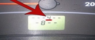
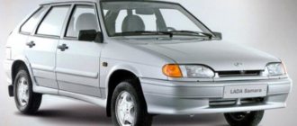
How to find out which ECU is on the VAZ 2114 – January 7.2 January 4 Bosch M1.5.4
Today, there are 8 (eight) generations of electronic control units, which differ not only in characteristics, but also in manufacturers. Let's talk about them in a little more detail.
ECU January 7.2 – technical specifications
And so now we move on to the technical characteristics of the most popular ECU January 7.2
The ECU uses a Siemens Infenion C-509 processor (the same as the ECU January 5, VS). The block’s software is a further development of the January 5 software, with improvements and additions (although this is a controversial issue) - for example, an algorithm has been implemented, literally an “anti-shock” function, designed to ensure smoothness when starting and shifting gears.
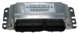
The ECU is produced (хххх-1411020-82 (32), firmware begins with the letter “I”, for example, I203EK34) and “Avtel” (хххх-1411020-81 (31), firmware begins with the letter “A”, for example, A203EK34) . Both the blocks and the firmware of these blocks are completely interchangeable.
ECUs of series 31 (32) and 81 (82) are hardware compatible from top to bottom, that is, firmware for 8-cl. will work in a 16-cl. ECU, but vice versa - not, because the 8-cl. block “does not have enough” ignition keys. By adding 2 keys and 2 resistors you can “turn” an 8-cell. block of 16 cells. Recommended transistors: BTS2140-1B Infineon / IRGS14C40L IRF / ISL9V3040S3S Fairchild Semiconductor / STGB10NB37LZ STM / NGB8202NT4 ON Semiconductor.
Typical ECU parameters January 7.2 for diagnostics
ECU January-4 - technical specifications
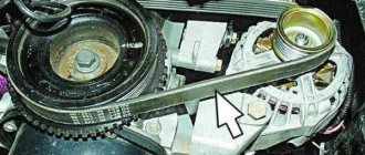
Therefore, during development, the overall and connecting dimensions, as well as the pinout of the connectors, were preserved. Naturally, the ISFI-2S and “January-4” blocks are interchangeable, but are completely different in circuit design and operating algorithms. “January-4” is intended for Russian standards; the oxygen sensor, catalyst and adsorber were excluded from the composition, and a CO adjustment potentiometer was introduced. The family includes control units “January-4” (a very small batch was produced) and “January-4.1” for 8 (2111) and 16 (2112) valve engines.
ECU January 4 second generation of electronic control unit VAZ 2114
The “Kvant” versions are most likely a development series with J4V13N12 firmware in hardware and, accordingly, in software, are incompatible with subsequent serial controllers. That is, the J4V13N12 firmware will not work in “non-quantum” ECUs and vice versa. Photo of KVANT ECU boards and a regular serial controller January 4
ECU diagram January 4
Features of the ECM: without neutralizer, oxygen sensor (lambda probe), with CO potentiometer (manual CO adjustment), toxicity standard R-83.
Bosch M1.5.4 – technical specifications
For Euro-2 toxicity standards, new modifications of block M1.5.4 appear (has an unofficial index “N”, to create an artificial difference) 2111-1411020-60 and 2112-1411020-40, satisfying these standards and incorporating an oxygen sensor, catalytic neutralizer and adsorber.
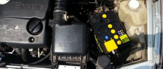
The brains of the Bosch M1.5.4 ECU
Also, for Russian standards, an ECM was developed for 8-class. engine (2111-1411020-70), which is a modification of the very first ECM 2111-1411020. All modifications, except the very first, use a wideband knock sensor. This unit began to be produced in a new design - a lightweight, leak-proof stamped body with an embossed inscription “MOTRONIC” (popularly “tin can”). Subsequently, ECU 2112-1411020-40 also began to be produced in this design.
Motorhelp.ru engine diagnostics and repair
Typical operating parameters of VAZ injection engines.
1.3 MAF ADC channel in rest mode: 0.996/1.016 V - normal, up to 1.035 V is still acceptable, everything above is already a reason to think about replacing the mass air flow sensor. Injection systems equipped with feedback from an oxygen sensor are able to correct, to some extent, incorrect readings of the mass air flow sensor, but there is a limit to everything, so you should not delay replacing this sensor if it is already worn out.
2. The engine is idling.
2.1 Idle speed. Typically this is 800 - 850 rpm with a fully warmed up engine. The idle speed value depends on the engine temperature and is set in the engine control program.
2.2 Mass air flow. For 8-valve engines, the typical value is 8-10 kg/h, for 16-valve engines - 7-9.5 kg/h with a fully warmed-up engine at idle. For the M73 ECU these values are slightly higher due to a design feature.
2.3 Length of injection time. For phased injection, the typical value is 3.3 - 4.1 ms. For simultaneous – 2.1 – 2.4 ms. Actually, the injection time itself is not as important as its correction.
2.4 Injection time correction factor. Depends on many factors. This is a topic for a separate article, but it’s worth mentioning here that the closer to 1,000 the better. More than 1,000 means the mixture is further enriched, less than 1,000 means it is leaner.
ECU pinout diagram January 7.2 VAZ 2114
The VAZ 2114 controller often breaks down. The system has a self-diagnosis function - the ECU queries all components and issues a conclusion about their suitability for operation. If any element fails, the “Check Engine” lamp will light up on the dashboard.
ECU pinout diagram January 7.2
It is possible to find out which sensor or actuator has failed only with the help of special diagnostic equipment. Even with the help of the famous OBD-Scan ELM-327, loved by many for its ease of use, you can read all engine operating parameters, find the error, eliminate it and delete it from the memory of the VAZ 2114 ECU .
ADC codes
ADC code parameters relate to analog sensors of the control system:
Physically, ADC codes reflect the voltage that the sensor produces. Typically, these parameters are used to test sensor circuits. If fault codes occur associated with a low or high signal level of such a sensor, then the control system operates in backup modes. In this case, the value of the parameter related to this sensor is selected either from the emergency table or calculated using specified formulas, for example, the coolant temperature with a faulty temperature sensor increases during engine operation.
If, during a physical change in the parameter measured by the sensor, the ADC code remains a constant value, then the electrical circuit connecting the sensor is inoperative.
How to remove and replace a faulty ECU on a VAZ 2114
When carrying out work to remove the VAZ 2114 ECU, do not touch the terminals with your hands. There is a possibility of damage to electronics due to electrostatic discharge.
- Using a screwdriver, unscrew the 3 screws securing the right panel of the instrument panel console and remove it.
- Release the clamp of the block with wires
- Disconnect the block from the ECU.
- Using a 10mm wrench, unscrew the 4 nuts securing the ECU to the bracket.
- We move the ECU forward and remove it from under the console.
- Remove the ECU from the bracket.
- Reinstall the ECU in reverse order.
Description of ADS1115 registers
The ADC has only 4 internal registers, all registers are 16-bit, respectively, for each write/read session, 2 information bytes are transmitted via the I2C interface (except for the register address byte). The registers are described in the table below:
| Address | Name | Register description |
| 0x00 | Conversion register | Conversion result storage register |
| 0x01 | Config register | Configuration register |
| 0x02 | Lo_thresh register | Setpoint register, minimum value |
| 0x03 | Hi_thresh register | Setpoint register, maximum value |
The configuration register is used to control the ADC; the register is described in the table below:
| Bit | Bit name | Bit value | Description |
| 15 | OS. The bit defines the state of the device and can only be written in low power mode | For recording | |
| No effect | |||
| 1 | Start conversion, for single conversion mode (low consumption) | ||
| For reading | |||
| Conversion in progress | |||
| 1 | Conversion complete | ||
| 14-12 | MUX. Multiplexer setup | 000 | AINp=AIN0 and AINn=AIN1 (default) |
| 001 | AINp=AIN0 and AINn=AIN3 | ||
| 010 | AINp=AIN1 and AINn=AIN3 | ||
| 011 | AINp=AIN2 and AINn=AIN3 | ||
| 100 | AINp=AIN0 and AINn=GND | ||
| 101 | AINp=AIN1 and AINn=GND | ||
| 110 | AINp=AIN2 and AINn=GND | ||
| 111 | AINp=AIN3 and AINn=GND | ||
| 11-9 | P.G.A. Amplifier Gain | 000 | FS=±6.144 V |
| 001 | FS=±4.096 V | ||
| 010 | FS=±2.048 V (default) | ||
| 011 | FS=±1.024 V | ||
| 100 | FS=±0.512 V | ||
| 101 | FS =±0.256 V | ||
| 110 | FS =±0.256 V | ||
| 111 | FS =±0.256 V | ||
| 8 | MODE. Operating mode | Continuous transformation | |
| 1 | Single conversion, low consumption mode (default) | ||
| 7-5 | D.R. Sampling frequency | 000 | 8 Hz |
| 001 | 16 Hz | ||
| 010 | 32 Hz | ||
| 011 | 64 Hz | ||
| 100 | 128 Hz (default) | ||
| 101 | 250 Hz | ||
| 110 | 475 Hz | ||
| 111 | 860 Hz | ||
| 4 | COMP_MODE. Comparator type | Comparator with hysteresis (default) | |
| 1 | Comparator without hysteresis | ||
| 3 | COMP_POL. Comparator polarity | Low active level (default) | |
| 1 | High active level | ||
| 2 | COMP_LAT. Comparator mode | Comparator without latch (default) | |
| 1 | Latch Comparator | ||
| 1-0 | COMP_QUE. Comparator control | 00 | Setting the output signal after one conversion |
| 01 | Setting the output signal after two conversions | ||
| 10 | Setting the output signal after four conversions | ||
| 11 | Comparator disabled (default) |
Where is the mass of the VAZ 2114 ECU located?
The first ground pin from the ECU on cars with a 1.5 engine is located under the instruments on the power steering shaft mount. The second terminal is located under the instrument panel, next to the heater motor, on the left side of the heater housing.
Location of the mass of the VAZ 2114 ECU
On cars with a 1.6 engine, the first terminal (mass of the VAZ 2114 ECU) is located inside the dashboard, on the left, above the relay/fuse block, under the sound insulation. The second terminal is located above the left screen of the center console of the instrument panel on a welded stud (fastened with an M6 nut).
What is corrected in the ECU firmware
Depending on the purposes of chip tuning, up to 1300 calibrations are made when programming the engine ECU. Most often the changes concern:
- fuel supply, enrichment thresholds, fuel supply restrictions during acceleration;
- hardware configuration bytes and error mask;
- torque, fuel supply and boost limits;
- operating algorithm of the mode manager;
- TP shutdown speed limits and V max.
boost pressure on turbocharged engines in economy and power modes;
Where is the relay and fuse of the VAZ 2114 ECU located?
The main part of the fuses and relays is located in the mounting block of the engine compartment, but the relay and fuse responsible for the electronic control unit of the VAZ 2114 are located in a different place.
Relays and fuses of the VAZ 2114 computer
The second “block” is located under the dashboard on the front passenger side. To access it you just need to unscrew a few fasteners using a Phillips screwdriver. Why is it in quotes, because there is no such block, there is an ECU (brains) and 3 fuses + 3 relays.
Suitable adapters and cables, programs and applications
The following equipment is suitable for analyzing and repairing the systems of this vehicle:
- VAG KKL – K-line exchange;
- VAG-COM 409.1;
- K-Line GM12-OBD2;
- Scan Tool Pro based on ELM327 1.5 chip.
The latest adapter should be used with version 1.5. Type 2.1 is not suitable for diagnosing ECU 2114 due to differences in module protocols. The connection occurs, but the module is not detected.
Among the programs we can note: OpenDiag, Diagnostic Tool, AvtoVAZ NEW, DiagnozNK.
KWP_D is one of the most reliable programs, supports Bosch 7.9.7 controllers. Allows you to control mechanisms (coils, nozzles, fans, etc.). Can record parameters. Works via K-Line.
For chip tuning, ChipTuningPRO or CombiLoader is used.
For earlier control units, a VAG K-Line adapter with OpenDiag software is used. This link allows you to read detailed information from memory.
Let's look at a summary table of the control modules used, their standards and the scanners used.
Chiptuner ru typical parameters
Optimal operation of a car engine depends on many parameters and devices. To ensure normal operation, VAZ engines are equipped with various sensors designed to perform different functions. What you need to know about diagnosing and replacing controllers and what are the parameters of sensors for VAZ injection engines is presented in the table in this article.
Diagnosis of VAZ 2112 16 valves with your own hands. Why pay extra?
It is much better if you diagnose the VAZ 2112 16 valves yourself.
This will guarantee that all faults present in the car will be found. If you learn how to diagnose your car yourself, you will likely notice signs of trouble. And you can eliminate it in a timely manner. In addition, despite modern equipment, the level of diagnostics in services is practically not growing. Not everywhere there are specialists who can correctly assess the condition of the car. Therefore, in most cases, self-diagnosis will be the best option.
True, special devices may be needed to carry it out, but their purchase will more than pay off in savings on trips to a car service center. It should be noted that the tenth VAZ family has the same microcontroller installed. Therefore, instrument diagnostics are performed here in the same way.
Visually. DIY diagnostics of VAZ 2112 16 valves
It starts with inspecting the car. Carefully inspect all components. Pay special attention to the suspension and steering. Parts must not have cracks or other damage. The brakes and body are also inspected. All these design elements are important for the normal operation of the car. However, many of their faults can be seen with the naked eye.
Typical operating parameters of VAZ injection engines
Checking VAZ sensors is usually carried out when certain problems are detected in the operation of the controllers. For diagnostics, it is advisable to know what malfunctions of VAZ sensors can occur; this will allow you to quickly and correctly check the device and replace it in a timely manner. So, how to check the main VAZ sensors and how to replace them after that - read below.
Basic parameters of controllers on VAZ injection engines
We greet you!
This site is one of the first (founded and published since 2001) and the most complete resources dedicated to chip tuning (changing the settings of automotive electronic fuel injection systems) and diagnosing faults in injection vehicles of Russian and foreign production.
All serial firmware presented on the site are read from factory ECU units; free tuning ones are either freely circulated on the RuNet or provided by their authors for free distribution. All reference information is taken from open sources (factory information letters, instructions, databases, etc.), systematized and provided for review in what we think is the most convenient form for assimilation and learning.
All materials and software posted on the site and available for viewing and downloading are non-commercial, distributed free of charge, on an “as is” basis and do not imply liability for possible damage caused to you or your car as a result of inept or incorrect use of materials and programs. The placement of advertising, commercial and copyright information has been agreed with the authors/copyright holders.
Corrections, additions, your thoughts and developments on the subject of the site are welcome. If you have serial or tuning firmware, programs, articles or interesting links, please send them. If you have questions or suggestions, welcome to the conference.
The content of the site is constantly updated and updated. If you have not found the information you need, come back later, it may well be that information on the issue you are interested in will appear, or ask your questions in the conference.
Please note that this website is for reference and informational purposes only and under no circumstances constitutes a public offer defined by the provisions described in Part 2 on page 437 of the Civil Code of the Russian Federation.
Any copying of site content without the consent of the administrator is prohibited .