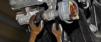
that means things are going well. ABS has not worked since I bought the car. Then, as it turned out, the front right wheel does not brake. First of all, I checked the fuses, they are intact. my cable vag som and elmka did not want to read abs. then a friend gave his elm. it read it and gave 2 errors
According to the voltage on this circuit, everything is normal. according to the second error, it means simply replacing the hydraulic unit assembly. This made me sad. I started looking for the abs unit. This led me to the Emex website. where they promised to bring Lada companies for 3400. ordered and paid. time passed, no delivery. The delivery deadline has expired. I'm writing to the manager. in response, either wait or refuse the order. refused and returned the money. let's look at local auto scraps. no one even knows about such blocks
The photo is actually from the Internet. may the people forgive me))) let's follow Avito. I found 2 options in another city 130 km away. nothing to do, let's go. the first block, at first glance, looked like it was dug out of sand, but inside everything was covered in sand. I went to look at the second block. looks dirty, but the canals are much cleaner. bought it, cost 2500. original Bosch. I came home, washed it and installed it. Bled the brakes and what do you think? The abs does not work, the errors are on and the unit still drains the battery and at the same time the same errors. but the front right wheel began to brake. at least there is progress somewhere)) I threw in the old block, it already showed an error on the front right wheel
Well damn. I can’t be so lucky that there are 2 different blocks and at the same time the same situation with the same errors. let's dig the connection wires. The block comes with 3 pluses. I pulled out all 3 fuses, but the abs continues to communicate. In this case, it is diagnosed even with the ignition off! where does abs get plus? and the unit is constantly in operation, regardless of the ignition, which is why the battery drains. I went home to coat myself. The most interesting thing is that if you turn on the ignition or drive while removing errors from the ABS, they no longer pop up. If you turn off or turn off the ignition, 2 errors occur at once. some kind of crap. I already called an electrician-diagnostician in another city 130 km away and arranged a visit. and then it dawned on me. On the Internet they write that the wheel sensors do not short to ground when checking. But what if you check if they are shorted to positive? but what if. and what do you think, the right front sensor gives me a stable plus. The bastard spent some time somewhere. and then the block itself apparently woke up and decided to throw an error on it
and all the time I drove with 2 lights on the tidy, indicating a problem with the abs
and here I do this. I disconnect the connector from the wheel sensor, plus it still goes to abs. then I just cut off the wire from the ABS itself and lo and behold, the errors were erased, the ABS began to turn off when the ignition was turned off, the battery stopped draining and the error was only on the right front wheel sensor. one light on the dashboard also went out and only the abs remained on
This means you need to dig a spit. and since the wind is strong and cold outside, think about it, let me just throw a wire for testing. I throw in the wire and lo and behold, when you turn on the ignition, all the abs lights go out immediately!
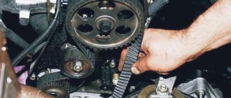
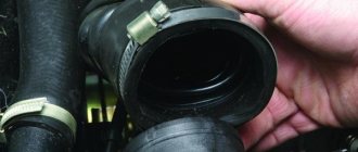
It can be easily treated by loosening the belt, adjusting it and tightening it. the whistle disappeared))) sorry for the many letters. All this was done for 2 months))
Hi all! This time the entry will not contain a lot of useful information, more for reporting purposes, but someone may learn something useful. So, even in winter it was noticed that sometimes the front wheels jam a little, because after driving the caliper was warm. But there was no desire to work in the cold, so the repairs were postponed. And finally the warmest time has come. I won’t describe how to change it, there’s a lot of information, I’ll just say that I installed Trialli brake cylinders on both sides
, if anyone needs, here is the article number: CF308 and CF208.
The replacement process itself is not tricky, only after replacement you need to bleed the brakes. Now everything works great, nothing gets hot!
With the rear brakes, it was only planned to change the pads with all the springs, drums and the brake cylinder on the right wheel.
But during the repair it was also discovered that the right rear wheel bearing was faulty, which means it needs to be replaced! I installed the bearing that was in stock, here is the article number: CR001. The pads for Nippon viburnum with ABS are: ABS1703, and a set of springs: SFK163.
Replacing the pads in the rear drums is not a tricky matter, there is nothing to describe, but because... I also changed the brake cylinder on the right, so I also had to bleed the system. To replace it, you also need to loosen the handbrake, otherwise the new pads with the new drums simply won’t fit, well, at least I’ll rub wildly. I had to loosen the handbrake completely, and then tighten it a little to 3 clicks.
Well, the last of the problems was that the ABS sensor began to fail again, only if last time it did not work at all, now it happened from time to time. Having reached it, I measured its resistance and the verdict was made that the sensor itself had come to an end. I bought a new sensor, article number: 0 265 007 886, and since the problem of a rotten contact had already visited me, it was decided to move the connecting contact from under the bottom to the interior. In this case, it was possible to install a regular connector instead of a sealed one. I installed the terminals, like male-female, inserted them into the connector and connected them. It feels great under the back seat!
Now the brakes are in perfect order, I hope it will all last a long time and be effective! Thank you all for your attention!
Currently, all LADA models (Lada XRAY, Vesta, Largus, Granta, Kalina, Priora, Niva 4×4) without exception are equipped with ABS (anti-lock braking system). During the operation of the car, many owners notice that the ABS and ESC lamps (if this system is available) light up on the instrument panel. Let's figure out how to solve this problem and improve the design.
Why does the ABS and ESC light come on?
ABS malfunction may be caused by:
- failure of wheel rotation sensors;
- malfunction of the hydraulic valve block;
- damage to the wiring.
If the ABS malfunction indicator light comes on, you must contact a service station as soon as possible for diagnostics (read error codes) and repairs.
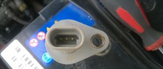
The most common cause of ABS failure is damage to the wiring near the ABS sensor connector. It is located under the fender liner, but is still not well protected from moisture and dirt.
As a result, the wires oxidize and break, and the ABS lamp lights up.
Finishing touches
This completes the replacement of the ABS sensor. With proper installation quality and compliance with the necessary requirements for parts (including their quality - beware of fakes), the car’s on-board computer should not display any information about a malfunction of the ABS. Before installing the wheel, you should turn on the ignition and check the on-board computer for such errors. And only after making sure that there are no errors can you install the wheel in place.
Lada Kalina 2. REMOVAL AND INSTALLATION OF FRONT WHEEL SPEED SENSORS
7. . and disconnect it.
8. Loosen the left front wheel bolts, lift the front of the car, place it on reliable supports and remove the wheel.
fist matte. During installation, do not rotate the sensor around its longitudinal axis. The increase in resistance to movement of the sensor should only be felt the last 2 mm before it is completely seated in the bracket. If the sensor enters the knuckle bracket hole with great resistance from the very beginning of installation, remove the sensor and eliminate the cause of the jamming (dirt, burr on the body, etc.)
It is strictly forbidden to press in the wheel speed sensor with a hammer. If, when driving the vehicle after replacing the wheel speed sensor, the anti-lock brake system fault warning light does not go out, contact a service station for ABS diagnostics.
Inductive passive sensor design
In many cars (both domestic and imported), a passive induction sensor is used as an ABS sensor, which is a coil wound on a magnetic core. It is installed opposite a toothed disk mounted on the hub axis. When the vehicle moves, an alternating voltage appears at the sensor terminals, the frequency of which depends on the speed of rotation of the wheel.
On a note! We have already written about how to check the active Hall sensor, which is used in some car models as an ABS sensor.
How to repair wiring
We remove the wheel, and then the locker (for the front wheel, turning out the fastening screws) or the protective shield (for the rear wheel, turning out the two fastening nuts “10”). Press the latch and disconnect the block with wires from the ABS sensor. We inspect the connector and make sure there is no corrosion or damage. In case of damage, we restore the integrity of the wires:
We treat it with a special means for cleaning electrical contacts (for example, graphite grease) and clean the contacts from oxides. We clean the wheel speed sensor and the surface around the sensor from dirt.
Attention! Keep ABS sensors away from magnets as this may cause damage.
Ways to check functionality
To determine the condition of a part, we will perform a series of steps to diagnose it, moving from simple to complex:
- Let's check the fuses by opening the unit (inside the passenger compartment or in the engine compartment) and inspecting the corresponding elements (indicated in the repair/operation instructions). If a burnt component is found, we will replace it with a new one.
- Let's inspect and check:
- integrity of connectors;
- wiring for abrasions that increase the risk of a short circuit;
- contamination of the part, possible external mechanical damage;
- fixation and connection to ground of the sensor itself.
If the listed measures do not help to identify a device malfunction, it will have to be checked using instruments - a tester (multimeter) or an oscilloscope.
Tester (multimeter)
This method of diagnosing the sensor will require a tester (multimeter), instructions for operating and repairing the car, as well as PIN - wiring with special connectors.
The device combines the functions of an ohmmeter, ammeter and voltmeter
Tester (multimeter) is a device for measuring electric current parameters, combining the functions of a voltmeter, ammeter and ohmmeter. There are analog and digital device models.
To obtain complete information about the performance of the ABS sensor, you need to measure the resistance in the device circuit:
- We lift the car with a jack or hang it on a lift.
- Remove the wheel if it prevents access to the device.
- Remove the cover of the system control unit and disconnect the controller connectors.
- We connect the PIN to the multimeter and the contact socket of the sensor (the connectors for the rear wheel sensors are located inside the cabin, under the seats).
We connect the PIN to the tester and the contact socket of the sensor
The device readings must correspond to the data specified in the repair and operation manual for a particular vehicle. If the device resistance:
- below the minimum threshold - the sensor is faulty;
- approaches zero - short circuit;
- unstable (jumping) at the moment of twitching of the wire - a violation of contact inside the wiring;
- infinity or no readings - wire break.
Attention! The resistance of the ABS sensors on the front and rear axles is different. The operating parameters of the devices are 1–1.3 kOhm in the first case and 1.8–2.3 kOhm in the second.
Video “Diagnostics of the ABS sensor”
How to check using an oscilloscope (with connection diagram)
In addition to self-diagnosis of the sensor with a tester (multimeter), it can be checked using a more complex device - an oscilloscope.
Replacing ABS sensors
If the cause of the malfunction is not in the wiring, but in the ABS sensor itself, we replace it. To do this, first unscrew the fastening screw with a Torx T30 key, and then remove the sensor wiring harness from the bracket. The photo shows a Lada Vesta car; on other Lada models the work is performed in a similar way.
Instructions for replacing the front wheel ABS sensor:
Instructions for replacing the rear wheel ABS sensor:
Choosing rear brake pads for Lada Largus
The rear pads on the Lada Largus with 8 valves have dimensions of 203x38 mm, Largus with a 16-valve engine is equipped with pads with dimensions of 228x42 mm.
| Manufacturer | engine's type | vendor code | approximate price |
| ORIGINAL | |||
| RENAULT (France) | 8V | 440601749R, 7701208111 | 2400 rub. |
| 16V | 7701210109 | 3000 rub. | |
| LADA (Russia) without ABS | 8V | 7701208111 | 2100 rub. |
| 16V | 7701210109 | 2500 rub. | |
| ANALOGUES | |||
| BOSCH (Germany) | 8V | 986487585 | 1300 rub. |
| 16V | 986487754 | 1800 rub. | |
| TRW (Germany) | 8V | GS8729 | 1700 rub. |
| 16V | GS8780 | 2000 rub. | |
| FERODO (Switzerland) | 8V | FSB519 | 1500 rub. |
| 16V | FSB4031 | 1600 rub. | |
| BREMBO (Italy) | 8V | S 61 520 | 1300 rub. |
| 16V | S 68 546 | 1900 rub. |
For safe operation of the machine, all pads on one axle should be replaced, regardless of the reason for the repair.
How to modify the design
To protect the wiring harness from the environment, you can use a D-shaped seal. We lay the wires in it and wrap it with electrical tape. We put everything in the corrugation. We glue the cover covering the ABS sensor connector around the perimeter with the same sealant. This will prevent moisture and dirt from entering the area where the sensor and connector are located.
Attention! If the ABS fails, the brakes remain operational, but the braking efficiency is reduced, which is especially dangerous on some surfaces. See why.
The anti-lock braking system is an integral option of any modern car from economy to premium class. The ABS system allows you to drive a car comfortably and safely on any surface, even the most difficult. During the operation of the car, the driver may encounter the problem of a non-functioning anti-lock braking system (ABS) and, as a result, ineffective braking of his car. In this case, the ABS sensor may need to be replaced. Depending on the age and condition of the vehicle, replacing an ABS sensor can be quite a labor-intensive process.
A little historical background
We have already discussed above a possible situation where the driver cannot cope with the car for purely psychological reasons. To eliminate such a scenario when driving a car, an anti-lock braking system was developed.
Its first samples appeared in the last century, in the seventies, but due to the lack of a suitable and reliable element base they were not widely developed.
With the advent of digital chips and affordable microprocessors and microcontrollers, the situation changed radically. Thanks to these elements, the ABS system appeared on the car. » alt=»»> It happened in 1978, and the first car with such a system was one of the Mercedes.
Principle of operation
It works as follows: in the gearbox there is a special mark on the gear wheel, which, when this wheel rotates, generates an impulse using a speed sensor. It is by the frequency of these pulses that the speed of the Lada Granta is determined.
Attention! If your Lada Granta is equipped with an ABS system, then the speed is read from the ABS sensors. In this case, the speed sensor at the gearbox is not connected and acts as a plug.
The DS on the Grant, like on many cars, is located quite low, so it is exposed to water and dirt. If we remember that the speed sensors themselves on domestic cars are not highly reliable, then it becomes clear why they fail so often.
Signs of a malfunctioning speed sensor:
- The speedometer needle does not react to speed in any way (it lies at zero);
- Electric power steering does not work;
- The speedometer readings change, but do not correspond to reality.
Checking the voltage on the sensor winding
Another way to check the performance of ABS sensors is to measure the output voltage that appears on the winding when the wheel rotates. To do this we do the following:
- We hang the wheel using a jack and remove it.
- We find the ABS sensor and disconnect its connector from the wiring leading to the control unit.
- We switch the multimeter to AC voltage measurement mode.
- We connect the probes to the contacts of the sensor connector.
- Rotate the wheel hub (at a speed of 1÷2 rpm).
- If there is a voltage of 200÷1700 mV (its value varies depending on the specific sensor model), it can be stated that the sensor is working. There's no reason to worry. If you were unable to find the technical specifications of the sensor, it is worth checking all ABS sensors installed on the car in a similar way. If, as a result of testing, a low voltage is detected on one of them (compared to the others), this indicates that it is not operating correctly.
On a note! If, when measuring the resistance of all sensors, the ohmmeter readings indicate their performance, but when the wheel rotates, a low voltage (or absence) appears on the sensor windings, then this may be a consequence of wear or breakage of the gear wheel.
ABS installation
First you need to put the car on a jack and remove the wheel. Next, unscrew the caliper mounting bolts using the appropriate wrench. Use a screwdriver to press out the caliper and remove it. To prevent brake fluid leakage, the brake hose must be clamped. Next, the caliper fitting is disconnected and a new one is installed in its place, with new brake pads (you need to select them carefully - you need a model that has a seat for the ABS sensor). After this, the ABS sensor itself is installed. It is important not to confuse the sensors of the front and rear wheels; they have design differences.
Let's move on to replacing the CV joint. First you need to turn the wheel in the direction from which you plan to replace the part. The locknut is unscrewed (during assembly it must be replaced with a new one). The ball joint is unscrewed from the steering knuckle.
Using a drift or a special puller, the CV joint spline is knocked out of its seat and then removed from the drive shaft. When installing a new CV joint, it is better to change the boot along with it. In this case, it is necessary to treat the surface under the boot with lithol.
When starting to install the hydraulic modulator, you need to remove the negative terminal from the battery. Next, remove the modulator cover and disconnect the electrical connectors. Carefully disconnect the brake pipes to prevent fluid from draining and finally remove the modulator. A new ABS control unit is installed in conjunction with the new hydraulic modulator. After this, two additional relays are installed (installation locations depend on the specific car model). The brake pipes and electrical wiring are connected.
ABS installation complete! The brakes must be bled before use.
Malfunctions of the ABS hydraulic unit
In some cases, the cause of anti-lock brake system failure is the hydraulic unit. The consequence of a malfunction of the hydraulic unit is a complete shutdown of the system, and repairs are required to return the system to working condition. Sometimes the hydraulic unit cannot be repaired and requires replacement, but in any case the unit must be dismantled. In order to remove the hydraulic block of the anti-lock braking system, you need to perform the following steps:
Thanks for subscribing!
- Place the car on a lift and remove the negative terminal from the battery.
- Disconnect the wiring harness from the hydraulic unit.
- Unscrew the brake pipes from the hydraulic unit and plug them to prevent dirt from entering.
- Remove the tubes and wires from the clamps.
- Remove the block by unscrewing the three nuts securing the bracket.
Assembly is carried out in reverse order. After assembly, it is important to program the parameters of the ABS control unit.
Replacing the ABS sensor
Almost all cars produced today have ABS, which has repeatedly proven its effective operation: when braking, the wheels spin a little, hence the high braking efficiency. In critical driving situations, this gives the driver of a car with ABS an additional chance to maneuver safely. Especially young drivers, whose skills are not yet sufficient to drive a car without additional safety systems, cannot do without ABS.
The operation scheme of ABS on VAZ cars is as follows: pulse signals from the ABS sensors enter the ABS control unit. If one wheel is blocked, the hydraulic modulator, based on a command from the control unit, limits the pressure in the corresponding channel.
If possible, it is best to place the car on a lift or drive it into a viewing hole. In the absence of such conditions, you can get by with lifting on a jack.
Scheme of work
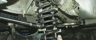
First you need to remove the wheel. Consider in advance the safety of your operations. The car should not roll or fall off the jack during repairs! The wheel has been removed. The sensor is located behind the brake caliper. Looking behind it, you can see what size keys are needed to remove and replace the sensor. Since the sensor is located at a fairly low point in the car (also in constant contact with dirt and water), the threaded connections can simply “sour”. Various means such as WD-40 liquid will help in the fight against this problem.
You can go a slightly different route and remove the caliper and brake disc. This way you can also access the sensor.
Next, you need to hold the metal part of the ABS sensor with suitable pliers and, swinging it in a pendulum motion, pull it towards you. Be careful - slipped pliers can damage the plastic protection of the sensor (which can lead to contamination of the sensor). When removing the part, you can use a flat screwdriver (or better, two). If a hole forms between the sensor body and the caliper, a screwdriver must be inserted into this hole and, prying the part in a circle, try to remove it. A partner can be a great help in this process if he also uses a screwdriver, but on the opposite side of the part (this way it will come out faster and more evenly). If you managed to remove the part by 5 mm or more, then you can put the tools aside and try to remove the sensor with your hands using rotational or pendulum movements. The ABS sensor has been removed.
Next, pay attention to where the wiring from the sensor goes and find where it is connected.
As a rule, the connection is made through the ABS electronic control unit (located under the hood of the car). Installing a new sensor occurs in the reverse order.
Main types
The ABS sensor is considered the primary measuring part of the anti-lock braking system.
The device consists of:
- A meter placed permanently near the wheel;
- An induction ring (rotation indicator, impulse rotor) installed on a wheel (hub, wheel bearing, CV joint).
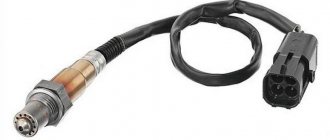
The sensors are available in two versions:
- Straight (end) cylindrical shape (rod) with a pulse element at one end and a connector at the other;
- Angled with a connector on the side and a metal or plastic bracket with a hole for a mounting bolt.
Two types of sensors are available:
- Passive - inductive;
- Active - magnetoresistive and based on a Hall element.
ABS allows you to maintain controllability and significantly increase stability during emergency braking
Passive
They are distinguished by a simple operating system, but are quite reliable and have a long validity period. Does not require a power connection. An inductive sensor is essentially an induction coil made of copper wire, in the middle of which there is a stationary magnet with a metal core.
The meter is located with the core to the pulse rotor in the form of a wheel with teeth. There is a certain gap between them. The rotor teeth are rectangular in shape. The opening between them is equal to or slightly larger than the width of the tooth.
While the vehicle is in motion as the rotor teeth pass near the core, the magnetic field penetrating the coil is constantly changing, forming an alternating current in the coil. The frequency and amplitude of the current are directly dependent on the speed of the wheel. Based on processing of this data, the control unit issues a command to the magnetic valves.
Article on the topic: How to check the fuel pump relay yourself
The disadvantages of passive sensors are:
- Relatively large dimensions;
- Poor accuracy of readings;
- They begin to function when the car picks up speed over 5 km/h;
- Triggered by minimal wheel rotation.
Due to frequent errors, they are installed extremely rarely on modern cars.
Magnetoresistive
The work is based on the property of ferromagnetic materials to change electrical resistance when exposed to a constant magnetic field.
The part of the sensor that controls changes is made of two or four layers of iron-nickel plates with conductors applied to them. Part of the element is installed in an integrated circuit that reads changes in resistance and generates a control signal.
The impulse rotor, which is a magnetized plastic ring in places, is rigidly fixed to the wheel hub. During operation, the magnetized sections of the rotor change the environment in the plates of the sensitive element, which is recorded by the circuit. Its output produces pulsed digital signals that enter the control unit.
This type of device controls the speed, direction of rotation of the wheels and the moment they come to a complete stop.
Magnetoresistive sensors record changes in the rotation of vehicle wheels with great accuracy, increasing the efficiency of safety systems.
Based on Hall element
This type of ABS sensor operates based on the Hall effect. In a flat conductor placed in a magnetic field, a transverse potential difference is formed.
Hall effect - the appearance of a transverse potential difference when a conductor with direct current is placed in a magnetic field
This conductor is a square-shaped metal plate placed in a microcircuit that includes a Hall integrated circuit and a control electronic system. The sensor is located on the opposite side of the pulse rotor and has the form of a metal wheel with teeth or a plastic ring, magnetized in places, rigidly fixed to the wheel hub.
The Hall circuit continuously produces signal bursts of a certain frequency. At rest, the signal frequency is reduced to a minimum or dies out completely. During movement, magnetized areas or rotor teeth passing by the sensing element cause changes in the current in the sensor, which are recorded by the tracking circuit. Based on the received data, an output signal is generated and sent to the control unit.
Sensors of this type measure speed from the beginning of the vehicle’s movement and are distinguished by the accuracy of measurements and the reliability of their functions.
Methods for self-diagnosis of ABS sensors on cars
If you have a car with a more or less decent ABS system, then it may also contain self-diagnosis of this system. For example, on some BMWs, even old ones, there is a system that not every car owner knows about. After starting the engine, the ABS light comes on for three seconds, then immediately after it goes off, press the brake pedal five times. The self-diagnosis system will start, and the number of blinks of the light will tell you which modules in the anti-lock braking system were faulty. Read the instructions about the self-diagnosis capabilities of your machine. You can check the sensors in another way:
Signs of a faulty ABS Lada Vesta
Before identifying a faulty anti-lock brake system and answering the question of how to fix the ABS, it is important to understand the signs of failure. And the first sign of an ABS malfunction is a special lamp on the instrument panel. If the system does not recognize the error, then the malfunction can be determined by several external signs:
- When you press the brake pedal all the way, the wheels are locked. This indicates that the ABS system is completely disabled and does not work.
- When you press the brake pedal all the way, vibration is felt, but the handling “leaves much to be desired.” This is an indication that ABS does not work on all wheels. The ABS sensors or hydraulic unit have probably failed.
If the sensors fail, you can get by with little expense by simply replacing them with new ones. If other parts of the system break down, repairs can cost a pretty penny. Let's look at how to repair ABS by dividing the system into 3 units.
[No flooding] Anti-lock brake system Kalina and Priora
ANTI-LOCK BRAKE SYSTEM FOR CAR FAMILIES LADA KALINA AND LADA PRIORA – DEVICE, DIAGNOSTICS, REMOVAL AND INSTALLATION OF MAIN UNITS
Carry out work in accordance with the requirements of the “Inter-industry rules for labor protection in road transport” POT RM-027-2003 and the labor protection instructions for mechanics in force at the enterprise. ATTENTION. When dismantling the hydraulic unit and pipelines, take measures to prevent brake fluid from spilling. 1 General description of the system, features of the design and operation The anti-lock braking system (ABS) is part of the working brake system of a car and is designed to automatically regulate the degree of wheel slip in the direction of their rotation during braking by changing the brake fluid pressure in the working brake cylinders in order to prevent loss controllability and stability of the vehicle and increase braking efficiency. ABS also performs the functions of distributing braking forces along the axes of the vehicle and distributing braking forces along the sides of the vehicle when braking in a turn. ABS consists of the following main components: — hydraulic unit (part 11180-3538010-00); — two front wheel speed sensors (part 11180-3538350-00); — two rear wheel speed sensors (part 11180-3538370-00); — two front wheel rotors (part 11180-3538390-00). The front wheel rotor is part of the outer joint (part 11186-2215012-00); — two rear wheel rotors (part 11180-3538400-00). The hydraulic unit (HA) structurally consists of an electronic control unit (ECU) and a hydraulic modulator containing electromagnetic valves (EMV), a return pump and a return pump electric motor (ERM). Wheel speed sensors (DSS) generate signals about the speed of each wheel of the vehicle, which are transmitted to the electronic control unit of the hydraulic unit. The operation of wheel sensors is based on the principle of electromagnetic induction. When the wheel rotates, the teeth and cavities of a special rotor pass past the sensor and induce an electrical signal in the sensor winding, the frequency of which is proportional to the angular speed of the wheel and the number of teeth on the rotor. The electronic control unit logically processes wheel speed signals and, depending on their condition (excessive acceleration or deceleration of the wheel), sends control commands to the hydraulic modulator.
Figure 1 — Schematic diagram of the ABS of cars of the LADA KALINA, LADA PRIORA families: K1 – front harness block to the hydraulic unit; K2 – hydraulic unit connector; PL – front left; PP – front right; ZL – rear left; ZP – rear right; VP – inlet; VYP - graduation
Based on received commands, the hydraulic modulator, by turning on or off the solenoid valves, reduces, increases or maintains constant the pressure of the brake fluid in the wheel brake cylinders, thereby ensuring optimal control of the braking forces. When the pressure decreases, excess brake fluid is pumped by the return pump into the master cylinder.
3 Diagnostics The ABS condition is monitored by diagnostic indicators (orange ABS and EBD symbols) located in the instrument cluster, which, after turning on the ignition, should turn on for 3 seconds and turn off. If a malfunction occurs in the ABS, the electronic control unit of the hydraulic unit turns on the corresponding diagnostic indicator. To view fault codes and ABS parameters, the software and hardware complex “AS: Diagnostics” is used. The list of ABS fault codes displayed by the diagnostic tool is given in Table 2. Table 2 Code Description of code C0035 Failure in the front left DSC circuit or unreliable signal C0040 Failure in the front right DSC circuit or unreliable signal C0045 Failure in the rear left DSC circuit or unreliable signal C0050 Failure in the rear right DSC circuit or unreliable signal C0060 Failure in the front left exhaust circuit EMC C0065 Failure in the front left intake circuit EMC C0070 Failure in the front right exhaust circuit C0075 Failure in the front right intake circuit EMC C0080 Failure in the rear left exhaust circuit C0085 Failure in the intake rear left EMC circuit C0090 Failure in the exhaust rear right EMC circuit C0095 Failure in the intake rear right EMC circuit C0110 Failure in the EVN circuit C0121 Failure in the relay circuit for turning on the supply voltage of the EMC C0161 Failure in the brake signal switch circuit C0245 Error in measuring the DSC frequency C0550 Internal computer malfunction C0800 Supply voltage is below or above the operating range
3.1 If fault codes C0035, C0040, C0045 and C0050 are detected, check the electrical circuits to the corresponding DSC for open and short circuits, check the supply voltage of the corresponding DSC (U supply DSC ? 0.8 U supply ECU). 3.2 If fault code C0110 is detected, check the supply voltage at contact 2 of the harness block to the hydraulic unit. 3.3 If fault code C0121 is detected, check the supply voltage at contact 3 of the harness block to the hydraulic unit. 3.4 If fault code C0161 is detected, check the electrical circuit to the brake light switch for open and short circuit. At contact 20 of the harness block to the hydraulic unit there should be: - low-level input voltage no more than 0.3 U power; — high-level input voltage of at least 0.8 U supply. 3.5 If fault code C0245 is detected, check the reliability of the DSC fastening and the gaps between the DSC and the rotor. The gap between the front wheel speed sensor and the front wheel rotor teeth should be (0.45-1.55) mm (set of feeler gauges). The gap between the rear wheel speed sensor and the rear wheel rotor should be (0.2-2.3) mm (set of feeler gauges). 3.6 If fault code C0800 is detected, check the supply voltage at contact 18 of the harness block to the hydraulic unit. It should be within (10-16) V. 3.7 If fault codes C0060, C0065, C0070, C0075, C0080, C0085, C0090, C0095, C0550 are detected, replace the hydraulic unit.
4. Hydraulic unit of the anti-lock brake system - removal and installation Removal: - place the car on a two-post lift, apply the parking brake and turn off the ignition (electrohydraulic lift type P3-T-SP with a lifting capacity of 3 tons); — disconnect the plug block of the front wiring harness from the hydraulic unit; — disconnect the brake pipes going to the brake mechanisms from the hydraulic unit of the anti-lock brake system. Install plugs in the holes of the hydraulic unit and on the brake pipes (wrenches type 41 08 11 13 f. “Stahlwille”, 256 11/13 f. “USAG” for brake pipe fittings, technological plugs); — disconnect the pipe of the primary and secondary circuits of the main brake cylinder from the hydraulic unit of the anti-lock braking system. Install plugs in the hole of the hydraulic unit and on the brake pipe (wrenches type 41 08 11 13 f. “Stahlwille”, 256 11/13 f. “USAG” for brake pipe fittings, technological plugs); — for cars of the LADA PRIORA family, unscrew the three nuts securing the hydraulic unit bracket to the front left side member (replaceable head 13, wrench and extension or wrench type IP-3111); — for cars of the LADA KALINA family, unscrew the two bolts securing the hydraulic unit bracket to the front left side member (replaceable head 13, wrench and extension or wrench type IP-3111); — remove the hydraulic unit with the bracket assembly from the car body; — unscrew the two nuts and disconnect the hydraulic unit from the bracket (spanner 10).
Installation: CAUTION. When installing a hydraulic unit from spare parts, the safety tape must be removed immediately before connecting the brake lines.
— install the hydraulic unit on the bracket and secure it with two nuts. Nut tightening torque - from 7.0 to 10.0 N.m (from 0.7 to 1.0 kgf.m) (replaceable head 10, wrench, torque wrench); — install the hydraulic unit with the bracket assembly on the car body: • for cars of the LADA KALINA family, tighten two bolts with washers securing the hydraulic unit to the front left side member (replaceable head 13, wrench and extension or wrench type IP-3111); • for cars of the LADA PRIORA family, tighten three nuts securing the hydraulic unit bracket to the front left side member (replaceable head 13, wrench and extension or wrench type IP-3111); — remove the plugs and attach the brake pipes of the primary and secondary circuits of the main brake cylinder to the hydraulic unit. The tightening torque of the fittings is from 15.0 to 18.0 N.m (from 1.5 to 1.8 kgf.m) (replaceable insert type 41 08 11 13 f. “Stahlwille”, torque wrench type 50 18 00 04 f . "Stahlwille"); — remove the plugs and connect the brake pipes to the hydraulic unit of the anti-lock brake system. The tightening torque of the fittings is from 15.0 to 18.0 N.m (from 1.5 to 1.8 kgf.m) (replaceable insert type 41 08 11 13 f. “Stahlwille”, torque wrench type 50 18 00 04 f . "Stahlwille"); — check the brake fluid level in the brake hydraulic reservoir and, if necessary, bring it to normal. The brake fluid level in the reservoir must reach the “max” mark when the reservoir cap is removed (technological capacity, brake fluid in accordance with Appendix 1 of the current “Consumption standards for basic and auxiliary materials for the maintenance and repair of LADA vehicles”); — loosen the wheel bolts (replaceable head 17, knob and extension); — hang up the car, unscrew the wheel bolts and remove the wheels (replaceable head 17, wrench); - perform bleeding of the brake system in accordance with the requirements of TI 3100.25100.08020 “Hydraulic drive system of brakes and clutches of LADA vehicles - bleeding, filling, replacing brake fluid”; — install the wheels on the car and tighten the wheel bolts, lower the car. The tightening torque of the wheel bolts is from 75 to 92 N.m (from 7.5 to 9.2 kgf.m) (replaceable head 17, torque wrench); — check and, if necessary, bring the level of brake fluid in the hydraulic brake reservoir to normal (technological container, brake fluid); — check the effectiveness of the service brake by test drive or on a stand, in accordance with the requirements of TI 3100.25100.13062 “Diagnostics of the brake system of LADA vehicles.”
We're sorry, but the requests coming from your IP address appear to be automated. For this reason, we are forced to temporarily block access to the site.
Let's sum it up
There are many breakdowns that can affect the ABS system. But the most common type of malfunction is sensor failure. If your car's anti-lock braking system is showing problems, the first thing you should do is check the sensors. There are several methods for testing the correct operation of these parts, so you can choose the most convenient testing option. However, diagnostics alone will not help the matter; any problems that have arisen will have to be corrected.
Today you can find and purchase ABS sensors from any manufacturer. You can find both simple parts for replacing factory sensors and original system elements at very affordable prices. And selection in this case will play a very important role. Use the factory catalogs to select sensors that are completely suitable for your vehicle and match the functions of the ABS system. To ensure that the anti-lock braking system does not interfere with the quality operation of the car, but helps to perform important tasks when braking, monitor the serviceability of the sensors and carry out diagnostic and repair work in a timely manner. Moreover, you can change the sensors of this system yourself. How often does ABS show problems in your car?
Dear customers, in order to avoid errors when sending a rear wheel ABS (speed) sensor, induction 1118-3538370 / 0265007886, in the “Comment” line indicate the front or rear ABS sensor, your car model, year of manufacture.
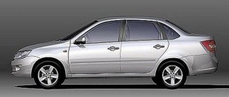
The main task of ABS is to maintain the stability and controllability of the Lada Kalina, Kalina 2, Priora, Priora 2, Granta when braking. By limiting wheel slip, ABS allows you to maintain vehicle controllability. The Electronic Brake Force Distribution (EBD) function is an extension of the ABS functions and is designed to optimally implement the vehicle's braking properties depending on its load and braking mode.
- Front right wheel speed sensor;
- Rear right wheel speed sensor 1118-3538370 / 0265007886;
- Rear left wheel speed sensor 1118-3538370 / 0265007886;
- Front left wheel speed sensor;
- The hydraulic unit is assembled with the control unit.
Why did it happen so?
Perhaps the automatic requests do not belong to you, but to another user accessing the network from the same IP address as you. You need to enter the characters into the form once, after which we will remember you and be able to distinguish you from other users exiting from this IP. In this case, the page with the captcha will not bother you for quite a long time.
You may have add-ons installed in your browser that can make automatic search requests. In this case, we recommend that you disable them.
It is also possible that your computer is infected with a virus program that is using it to collect information. Maybe you should check your system for viruses.
If you have any problems or would like our support team, please use the feedback form.
Even children probably know what ABS (Anti-lock Braking System) is. This system allows you to perform the most effective braking to stop the vehicle as quickly as possible. The system is electronic and is equipped with many sensors and a control unit, which ensures that the wheels do not lock during braking, that is, “do not skid.” Such an invention saves hundreds or maybe even thousands of lives on the road every day. The ABS system prevents skidding and loss of control, which is very important on slippery roads, as well as in case of emergency braking.
In this article, I will tell you how to check the ABS sensor if it malfunctions, as well as if an emergency indicator appears on the dashboard in the form of three English letters “ABS”. You will learn how to test the ABS sensor at home in various ways using a multimeter.
The most common breakdown in the ABS system is a circuit break, when communication is lost between the control unit and the sensor. This can happen for various reasons, which you will learn about a little later.
What to do if a breakdown is detected
What to do with the ABS sensor if a malfunction is detected? If the problem point is the device itself, it will have to be replaced, but in the case of electrical wiring, you can fix the defect yourself. To restore its integrity, we use the “soldering” method, carefully wrapping the joints with insulating tape.
If the ABS indicator on the dashboard lights up, this is a clear sign of a sensor failure. The described steps will help identify the cause of the breakdown, but if you lack knowledge and experience, it is better to contact a car service center. Otherwise, illiterate diagnostics of the condition, coupled with improper repair of the device, will reduce the effectiveness of the anti-lock braking system and can provoke an accident.
Publication date: December 05, 2022. Category: Automotive equipment.
ABS (anti-lock braking system), consisting of an electronic control unit, a hydraulic unit, rear and front sensors, is designed to prevent the car's wheels from locking during emergency braking. Its main purpose is to maintain vehicle controllability and stability, as well as to help reduce braking distances. Therefore, it is so important that all sensors installed in the car are in good working order. To check them, it is not at all necessary to go to a car service center. You can deal with this problem yourself.
How to recognize a faulty ABS system or ABS sensor?
- As I already said, the corresponding indicator lights up on the panel; this can happen while driving, braking, or when turning the key in the ignition. In the latter case, the appearance of the inscription indicates self-diagnosis of the system; after you start the engine, the light should go out.
- If the ABS system malfunctions during braking, you will not hear the characteristic sound of the ABS unit located under the hood and will not feel the vibration that occurs when you sharply press the brake pedal and try to slip the wheels.
What is ABS and how does it work?
ABS (anti-lock braking system) is a system that prevents the wheels from locking during braking.
When your car's wheels skid, controllability drops sharply and the likelihood of an unfavorable outcome in an emergency increases. To eliminate sliding friction when the car stops, engineers developed this system. To understand how to repair ABS yourself, it is important to know the principle of operation of the system: the driver presses the brake pedal all the way and the wheels immediately lock. In a split second, the ABS control unit reads this information from the sensors and relieves the brake fluid pressure through the ABS hydraulic unit. As soon as the speed sensors “understand” that the wheel is spinning, the system turns off and the wheel is locked. Since this happens in a split second, the wheels are held at the limit of skidding. This whole process can be felt by the vibration of the brake pedal.
What to do first?
It is necessary to check the ABS sensors located near each wheel hub. Your task is to detect a violation in the connection of the sensors, a broken wire or damage to the ABS sensor housing. In any of these cases, you will one way or another see the corresponding indicator on the panel, well, provided that the system control unit itself is working and not “buggy”.
Checking the ABS sensor - measuring the resistance
For more details on how to check the ABS sensor, watch this video:
Checking the ABS sensor using a tester - measuring the voltage
- Let's jack up the wheel.
- Turn on the multimeter, set the DC voltage measurement mode.
- We connect the electrodes of the device to the connectors and check the readings, while rotating the wheel (about 1 rpm).
- A working ABS sensor will show voltage on the device
0.25-1.2 Volts. If the wheel rotation speed is higher, the readings will increase accordingly.
How to check a sensor with an oscilloscope?
To diagnose the serviceability or malfunction of the ABS sensor, you can even use an oscilloscope or, more simply, a tester. When connected, a graph will be displayed on the device; using amplitude analysis, you can judge the serviceability or malfunction of the sensor.
The problem is that this device is not available at every service station, not to mention the garage in which you are going to conduct all your “experiments”. The device is expensive and quite difficult to understand, so to work with it you need to have certain knowledge and skills.
In modern cars, the ABS system has a self-diagnosis function; using special software, you can read the error code and then decipher it using a special table.
Troubleshooting methods
Now that all the causes have been identified, we can begin to consider troubleshooting. But, before we begin, it is worth noting that a car enthusiast needs to have an idea of the design features of the engine if he wants to fix the problem himself. Otherwise, go directly to a car service center, in order to avoid other problems that, due to lack of experience, car enthusiasts usually create for themselves.
Sensors
Often, the reason why the check light on Kalina may come on is the failure of one of the sensors. Possible ones that are worth checking right away include: mass air flow sensor, idle speed control, crankshaft position sensor, oxygen sensor and coolant temperature sensor.
You can determine the cause by going through each sensor separately and using a tester to check their functionality.
But, there is a simpler and more effective way to determine the malfunction of a particular sensor, namely connecting to the electronic engine control unit. Here you can look at the errors and, by deciphering them, determine where the problem is.
Throttle
A clogged throttle valve can often cause the check engine light to come on because not enough air is supplied to the power unit. The solution to the problem is cleaning. This process can be carried out using carburetor cleaning fluid or VD-40 fluid.
The part is removed from the car and cleaned, after which it is installed in place. It is also recommended to check the throttle position sensor, which may have failed.
Injectors
One of the common reasons for the “check” icon to appear on the dashboard is a malfunction of one or more injectors that do not spray the fuel mixture properly. So, it is worth dismantling all the elements and checking them using a special stand.
If there is none, then you can use the traditional method by pouring flushing fluid into the fuel supply pipes and activating the injectors using the battery. This way it will be clear which injector is not working well. But, experienced auto mechanics recommend cleaning and checking the nozzles on a stand, since the effectiveness of the procedure is higher.
Fuel pump and filter
Another cause of the malfunction may be a malfunction of the gasoline pump or its filter. Lack of power or contamination of the filter elements leads to the fact that an insufficient amount of fuel will enter the power unit to form an air-fuel mixture.
This can also cause such a well-known automotive effect as engine tripping.
The malfunction can be cured by checking the functionality of the gasoline pump, as well as by replacing the filter inside the gasoline pump. It is also worth looking at the fuel filter, which could become clogged when pouring low-quality gasoline.
Air filter
A clogged air filter can cause insufficient air in the combustion chambers. So, to check this element, it must be dismantled, which is done quite simply. By inspecting the filter element, you can find out how dirty it is and whether the product needs to be replaced. So, after replacement, the check signal from the dashboard may disappear.
Spark plugs and high voltage wires
Wiring is also often the reason why the check icon lights up on the panel. This happens when the spark plug is inoperative or there is a breakdown in one of the high-voltage wires.
It is recommended to check spark plugs on a special spark plug stand. But, if there is none, then you can use the generally accepted “old-fashioned” methods. But high-voltage wires are checked using a conventional multimeter, where the resistance along each wire should be about 5 ohms. If a broken part is found, it must be replaced.
Petrol
But, in addition to the above reasons, the problem may lie on the surface. Thus, ordinary low-quality gasoline can cause the “Check Engine” icon to appear on the car’s dashboard. To eliminate the breakdown, it is necessary to drain the low-quality fuel and flush the fuel supply system. But, if you drive for a long time on such fuel, the batteries may fail, which should also be checked when flushing.
Is it possible to repair the ABS sensor?
The question of whether it is possible to repair this sensor is difficult to answer unequivocally; it increasingly depends on the degree of its damage and malfunction. If it’s all about simple damage to the wiring, then solving the problem will not be difficult. If the damage is more global, the core or winding is damaged, then most likely repairing such a sensor will simply not be possible and will require a complete replacement. Despite the fact that 99% of experts recommend replacing the sensor if it malfunctions or has problems with the winding, there are those who successfully restore these sensors at home using improvised means. You can find out more about this repair in the video below.
This video clearly demonstrates how to repair an ABS sensor at home.
That's all for me. Thank you for your attention, I hope you found it interesting and were able to learn something new for yourself. I look forward to your comments on this topic, perhaps you have encountered such a problem or managed to solve it. Until next time, bye.
Why does the ABS and ESC light come on?
ABS malfunction may be caused by:
- failure of wheel rotation sensors;
- malfunction of the hydraulic valve block;
- damage to the wiring.
If the ABS malfunction indicator light comes on, you must contact a service station as soon as possible for diagnostics (read error codes) and repairs.
The most common cause of ABS failure is damage to the wiring near the ABS sensor connector. It is located under the fender liner, but is still not well protected from moisture and dirt.
As a result, the wires oxidize and break, and the ABS lamp lights up.
How to repair wiring
We remove the wheel, and then the locker (for the front wheel, turning out the fastening screws) or the protective shield (for the rear wheel, turning out the two fastening nuts “10”). Press the latch and disconnect the block with wires from the ABS sensor. We inspect the connector and make sure there is no corrosion or damage. In case of damage, we restore the integrity of the wires:
We treat it with a special means for cleaning electrical contacts (for example, graphite grease) and clean the contacts from oxides. We clean the wheel speed sensor and the surface around the sensor from dirt.
Attention! Keep ABS sensors away from magnets as this may cause damage.
Checking the ABS control unit and electrics
How to repair an ABS unit with your own hands? The first thing to do is to understand the reasons. And one of the likely reasons for the failure of the anti-lock braking system is poor electrical contact. This may be due to broken wires, blown fuses and relays, as well as failure of the ABS control unit itself. Therefore, before you start replacing the ABS control unit, you need to make sure that the electrical circuits are in good condition: check the integrity of all wires and fuses, as well as the functionality of the relay.
Replacing ABS sensors
If the cause of the malfunction is not in the wiring, but in the ABS sensor itself, we replace it. To do this, first unscrew the fastening screw with a Torx T30 key, and then remove the sensor wiring harness from the bracket. The photo shows a Lada Vesta car; on other Lada models the work is performed in a similar way.
Instructions for replacing the front wheel ABS sensor:
Instructions for replacing the rear wheel ABS sensor:
How to modify the design
To protect the wiring harness from the environment, you can use a D-shaped seal. We lay the wires in it and wrap it with electrical tape. We put everything in the corrugation. We glue the cover covering the ABS sensor connector around the perimeter with the same sealant. This will prevent moisture and dirt from entering the area where the sensor and connector are located.
Attention! If the ABS fails, the brakes remain operational, but the braking efficiency is reduced, which is especially dangerous on some surfaces. See why.