On any four-stroke engine, a complete cycle is completed in two revolutions of the crankshaft - once the piston approaches top dead center at the end of the compression stroke, and a second time at the end of the exhaust stroke. This allows injection engines to use only the counting moment from the crankshaft position sensor as a reference signal. In this case, the operation of injection and ignition is called non-phased. At the end of exhaust, a second (idle) spark occurs, and the injector opens twice, part of the fuel is supplied to the open intake valve, and part to the closed one.
Thus, the injection system is simplified without losing any qualities that are actually noticeable to the owner. Instead of individual ignition coils, you can use a pair of fused ones, as is done on eight-valve VAZ engines. If we take Renault, then even on engines with individual ignition coils it is not phased: the coils of cylinders 1-4 and 2-3 are connected through the primary windings in series and fire simultaneously.
But the supply of some of the fuel to the closed intake valve at one “wonderful” moment went against the requirements of environmentalists: due to the poor evaporation of gasoline on a cold engine, it was necessary to increase the fuel supply while warming up. Even these milliliters no longer fit into more stringent environmental standards, so it was necessary to invent a method for phasing the injection operation so that fuel was supplied to the cylinder at the moment of the intake stroke. And on engines with direct injection it must occur strictly in one stroke.
Methods for checking the camshaft sensor
Before testing the sensor using a multimeter or other electronic tools, you must check its mechanical integrity.
In particular, it is installed in a housing with an O-ring, ensuring its secure fastening. We need to check its condition. It would also be useful to check the integrity of the sensor body, whether there are cracks or other damage on it. It is advisable to check the drive disk to see if the teeth are damaged or if there are metal shavings on the sensor body or nearby. On the Internet you can find information that supposedly the DPRV can be determined to work by simply checking its magnetic properties. In particular, bring a small metal part to its end (the working sensitive part), which should “stick” to the sensor. In fact, this is not the case, and a non-working DPRV may or may not have magnetic properties. Accordingly, verification must be performed using other methods.
There are two main ways to test the camshaft position sensor - using an electronic multimeter and using an oscilloscope. The first method is simpler and faster, but the second is more accurate and provides more diagnostic information.
Checking the camshaft sensor with a multimeter
To check the DPRV, dismantling is necessary. This is not difficult to do; you just need to disconnect the contact group of wires from it and unscrew the fastening bolt. You will also need a small metal object (ferrous metal so that it is magnetic) to test.
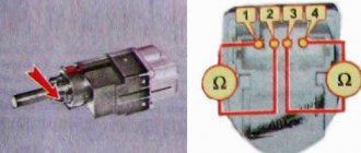
Connection diagram for checking phase sensor 21110-3706040
Connection diagram for checking phase sensor 21120-3706040
The algorithm for checking the sensor with a multimeter is as follows:
- Take a multimeter and switch it to the DC voltage measurement mode in the range up to 20 V (depending on the specific multimeter model).
- Disconnect the “chip” from the sensor by unclipping the latch.
- Remove the sensor from its mounting location.
- On the “chip” of the sensor 21110-3706040 of a VAZ car (and on many others), contact “A” corresponds to ground, contact “C” is the positive wire, comes from the control relay, contact “B” is the signal wire (middle). For sensor chip 21120-3706040, contact “A” corresponds to ground, contact “B” is the positive wire from the control relay, contact “C” is the signal wire.
- Check the presence of power on the chips. To do this, you need to turn on the ignition on the car (but do not start the engine) and do this with a multimeter. If there is no power to the chips, then you need to look for the reason. This could be faulty wiring (insulation damage, broken wires), failure of the control relay, or a glitch in the electronic control system (ECU).
- Next, you need to connect the sensors for testing according to the diagrams shown in the figure.
- Apply a voltage of 13.5±0.5V to the sensor (although less is allowed, for example, 12...12.5 Volts from the battery).
- If, when power is applied to the sensor, the voltmeter detects a lack of voltage on the sensor, then this indicates either a breakdown of the sensor itself, the test can be completed and you can prepare to replace the sensor with a new one.
- Measure the voltage between the positive and signal contacts. It must be equal to at least 90% of the supply voltage (that is, if the supply voltage is 12 Volts, then the voltage at the signal contact must be at least 10.8 Volts).
- Bring a metal object prepared in advance to the end of the sensor (its signal part). Re-measure the voltage at the signal contact. It should be no more than 0.4 Volts. Remove the plate - the voltage value should be restored to 90.100% of the supply. If there are any deviations during the verification process, it means that the sensor has failed and must be replaced.
Checking the DPRV using an oscilloscope
An electronic oscilloscope helps to understand how the camshaft position sensor works and whether it produces pulses at all. Usually they use a so-called electronic oscilloscope, that is, simply a simulator program installed on a laptop or other similar device. You need to connect to the camshaft sensor and take an oscillogram from it. Ideally, there should be a smooth comb diagram with one drop-out peak that corresponds to the rapper passing through the sensor. If the oscillogram has a different shape, additional verification is needed.
When diagnosing the camshaft sensor of Nissan cars (in particular, Nissan Almera) with an oscilloscope, the shape of the oscillogram will be different. It will not be smooth, but in the form of 3 impulses, then a space, then 4 impulses - a space, 2 impulses - a space and one impulse - a space. For engines from this automaker, this feature is the norm.
Signs of DPRV failure
There are several typical signs that indicate that the camshaft position sensor has failed. It is immediately necessary to clarify that the symptoms listed below may indicate completely different malfunctions. Therefore, it makes sense to perform additional diagnostics. So, signs of a DPRV breakdown:
- Problems with starting the engine, under any conditions - “cold”, “hot” and in other modes. This usually results in having to crank the starter longer.
- Unstable engine operation, “floating” operating and idle engine speeds.
- “Dips” in the movement of the car; when you press the accelerator pedal, it does not respond immediately, the dynamic characteristics of the car are lost (it accelerates poorly, does not pull, especially when loaded and when moving uphill).
- When the accelerator pedal is released, the engine stalls.
- Increased fuel consumption (by 10...20%).
- The Check Engine warning light on the instrument panel activates. It is necessary to perform additional diagnostics using an electronic scanner (for example, an ELM 327 device or its equivalent). In this case, typical errors regarding the operation of the sensor are numbers P0340, P0342, P0343.
In fact, the camshaft position sensor is a fairly simple and reliable device, so it rarely fails. More often, its wiring is damaged - the wires fray, the insulation on them is damaged, the so-called “chip”, the place where the sensor is connected to the car circuit, fails.
However, for cars that run on gasoline, the problems described above are not so clearly expressed. But a failed camshaft position sensor will cause many problems for owners of cars equipped with gas equipment, in particular the fourth generation. The malfunctions and problems described above can appear on such machines “in all their glory.” Therefore, owners of cars equipped with HBO are strongly recommended to diagnose and replace the sensor as quickly as possible if it is suspected of being faulty.
Signs of a malfunctioning crankshaft sensor
DMRV sensor Lada Kalina 8 valves
The main difficulty in determining a malfunction of the control system of an injection engine is that the symptoms of failure in the construction of many sensors and systems can be almost identical. The same thing is observed with the crankshaft position sensor. Since it affects almost all the main life support systems of the engine, the signs can appear very vague. In principle, there is nothing to break in the sensor, so its performance can only be affected by the cleanliness of the surface, and even then not too much. Well, the wiring in the most advanced cases may not make good contact. But we will check this. In the meantime, with these symptoms, unstable operation of the crankshaft position sensor is quite likely:
What are the main signs of a faulty crankshaft sensor?
- Unstable unmarried revolutions, revolutions float on their own and cannot be adjusted. However, the electronic control unit itself may be to blame here, without already reporting about the fuel pump, ramp and injector condition. And it wouldn't hurt to check the ignition.
- Loss of dynamics, failures when switching to high speed mode, failures during acceleration and even soft acceleration.
- Disgusting engine starting, and the car may not want to start either cold or hot. Not to mention those cases when the engine, seemingly, for no apparent reason, simply refuses to start. This means that the sensor has completely died and the engine management system does not understand that the crankshaft is turning. For the ECU, the shaft simply stands still.
There are no difficulties, the sensor can easily be checked on a diagnostic computer, or an error code will appear on the on-board computer indicating that the sensor is to blame. On the VAZ 2114, for example, on the final 2109, 2115 and other cars with this engine, the error code is 0335 or 0336. But this does not mean that the sensor is dead. The wire could simply break. How much it makes sense to diagnose the sensor with your own hands, everyone will decide for themselves, since the price of a new sensor for 2110 and all VAZ cars with injection engines is 155 rubles for 2015. It’s not so much money that you can’t afford to have such luxury in your garage as a reserve.
Video: Crankshaft position sensor. Examination
For the sake of sport, you can check the sensor yourself, although its work is scientifically checked with the support of an oscilloscope. You will need a tester to check. You can first check the resistance - for most sensors it should be within 700 Ohms. You can also check the sensor for elementary inductance. To do this, you need to connect the tester leads to the sensor wires, set the multimeter to about 200 mV. In this case, the sensor must respond to the appearance of any metal object by changing the voltage.
Do-it-yourself troubleshooting
An operational problem should prompt a system check. You can do it yourself in a relatively short time. If you are a novice driver or do not understand the intricacies, the best solution would be to contact a professional service center. There, the specialists will help eliminate all problems and breakdowns of the mechanism.
The crankshaft and camshaft sensors are diagnosed using a special tester. The cables are connected to the required terminal (A, B) in the appropriate order. The car starts, you should wait until it stops. It is important to carefully monitor changes in voltage.
In the first ten seconds, the voltage value should be equal to the on-board type value. In this case, the chain is not broken. If this does not happen, then it is closed or broken.
Sometimes there is no voltage when the circuit is intact. Such malfunctions often occur due to the fault of the controller. This is easy to check by connecting terminals A and C to the tester. As a result, there should be on-board voltage when the ignition is on. If this does not happen, then you need to look for a break further.
Features during diagnosis
Where is the idle speed sensor on the VAZ-2110: 8 and 16 valves
When the first suspicions arise, it is recommended to proceed with a thorough examination. If you cannot do this, it is recommended that you turn to professionals.
The first thing to do is to find out the primary cause of the breakdown. There may be several of them:
- there is a short circuit in the circuit;
- the temperature of the power unit rises;
- the toothed disc is broken or damaged;
- the mounting lugs are damaged;
- phase sensor Kalina 8 cells or 16 cells offset.
If the “Check” lights up, which gives one of two errors - 0340, 0343, then the fault definitely lies with the phase device. Perhaps the reason is in the connections.
DF ERRORS
If the VAZ 2114 is equipped with an on-board computer, if the device malfunctions, it will display one of the errors with code 0340 or 0343. Let’s analyze each of them in more detail.
- FAZ sensor error 0340 - indicates the absence of a DF signal. The cause of this error can be anything from oxidized contacts to mechanical damage to the device. Solved by replacing the part with a new one.
- Error 0343 – high signal level of the phase sensor. Its cause, as a rule, is damage to the wiring itself or the terminals in the contact block, or their loose/oxidized connection.
Errors in the VAZ 2115 phase sensor are completely similar to the errors that occur on the fourteenth.
Signs of a faulty phase sensor
Where is the speed sensor located on a VAZ-2112 16 valves
If the phase sensor fails completely or partially, the electronic control unit forcibly switches the engine to paraphase fuel injection mode. This means that the timing of fuel injection is carried out according to the readings of the crankshaft sensor. As a result, each fuel injector injects fuel twice as often. This ensures that a fuel-air mixture is formed in each cylinder. However, it is not formed at the most optimal moment, which leads to a drop in engine power, as well as excessive fuel consumption (albeit small, although this depends on the specific engine model).
Symptoms of a faulty phase sensor are:
- fuel consumption increases;
- the toxicity of exhaust gases increases, the smell of exhaust gases will be felt, especially if the catalyst is knocked out;
- the engine begins to operate unstably, most noticeably at low (idle) speeds;
- the acceleration dynamics of the car, as well as the power of its engine, are reduced;
- the Check Engine warning light is activated on the dashboard, and when scanning errors, their numbers will be associated with the phase sensor, for example, error p0340;
- at the moment the engine starts in 3...4 seconds, the starter spins the engine “idling”, after which the engine starts (this is due to the fact that in the first seconds the electronic control unit does not receive any information from the sensor, after which it automatically switches to emergency mode, based on data coming from the crankshaft position sensor).
In addition to the above symptoms, often when the phase sensor fails, problems arise with the vehicle’s self-diagnosis system. In particular, at the moment of starting, the driver is forced to turn the starter for a little more time than usual (usually 6...10 seconds, depending on the model of the car and the engine installed on it). And at this time, self-diagnosis of the electronic control unit occurs, which leads to the formation of corresponding errors and transfer of the engine to emergency operation mode.
Malfunctions of the phase sensor on a car with HBO
It is noted that when the engine is running on gasoline or diesel fuel, the unpleasant symptoms described above do not appear so acutely, which is why many motorists often use cars with a faulty phase sensor for a long time. However, if your car is equipped with gas equipment from the fourth generation and higher (which uses its own “smart” electronics), then the engine will work intermittently, and the driving comfort of the car will sharply decrease.
In particular, fuel consumption will increase significantly, the air-fuel mixture may be lean or, conversely, enriched, and engine power and dynamics will significantly decrease. All this happens due to a mismatch between the software of the electronic engine control unit and the LPG control unit. Accordingly, when using gas-cylinder equipment, the phase sensor must be changed immediately after its breakdown is detected. Using a machine with a damaged camshaft position sensor is harmful in this case not only to the engine, but also directly to the gas equipment and its control system.
Signs of DPRV failure
There are several typical signs that indicate that the camshaft position sensor has failed. It is immediately necessary to clarify that the symptoms listed below may indicate completely different malfunctions. Therefore, it makes sense to perform additional diagnostics. So, signs of a DPRV breakdown:
- Problems with starting the engine, under any conditions - “cold”, “hot” and in other modes. This usually results in having to crank the starter longer.
- Unstable engine operation, “floating” operating and idle engine speeds.
- “Dips” in the movement of the car; when you press the accelerator pedal, it does not respond immediately, the dynamic characteristics of the car are lost (it accelerates poorly, does not pull, especially when loaded and when moving uphill).
- When the accelerator pedal is released, the engine stalls.
- Increased fuel consumption (by 10...20%).
- The Check Engine warning light on the instrument panel activates. It is necessary to perform additional diagnostics using an electronic scanner (for example, an ELM 327 device or its equivalent). In this case, typical errors regarding the operation of the sensor are numbers P0340, P0342, P0343.
In fact, the camshaft position sensor is a fairly simple and reliable device, so it rarely fails. More often, its wiring is damaged - the wires fray, the insulation on them is damaged, the so-called “chip”, the place where the sensor is connected to the car circuit, fails.
However, for cars that run on gasoline, the problems described above are not so clearly expressed. But a failed camshaft position sensor will cause many problems for owners of cars equipped with gas equipment, in particular the fourth generation. The malfunctions and problems described above can appear on such machines “in all their glory.” Therefore, owners of cars equipped with HBO are strongly recommended to diagnose and replace the sensor as quickly as possible if it is suspected of being faulty.
The phase sensor (PF) is one of the many sensors that ensure engine operation.
The phase sensor is also called the “camshaft position sensor (CPS)”. This sensor is not installed in a carburetor engine, or even in the first models of VAZ injectors. The sensor is present in all 16-valve AvtoVAZ engines; On 8 valves with Euro-3 toxicity standards and with phased, sequentially distributed fuel injection; It is worth noting that in the period from 2004 to 2005, the mass introduction of phase sensors began on such engines as 2111, 2112,21114, 21124 with Bosch M7.9.7 and January 7.2 engine control units.
Why do you need a phase sensor?
The phase sensor is designed to determine the engine operating cycle and generate a pulse signal. Phase sensor with an integral sensor, i.e. includes a sensitive element and a secondary signal-to-pulse converter. The sensor's sensitive element operates according to the Hall principle, responding to changes in the magnetic field. The secondary element of the sensor contains a bridge circuit, an operational amplifier, and an output stage. The output stage is designed as an open collector. The operation of the phase sensor represents the choice of stroke for the first cylinder: the camshaft determines which valve is open and which valve timing. Carburetor engines do not have this sensor. The fact is that a carburetor engine supplies a spark plug at the moment of compression and at the end of the exhaust gases, and for this principle of operation the readings of the crankshaft position sensor (CPS) are sufficient. This type of engine operation is called the “ignition system”. On injection engines, when the phase sensor (DF) dies, the check light comes on and the engine switches from phased injection to the ignition system, that is, relying only on the DPKV readings.
What is the advantage of phased injection?
The phased injection system is designed as follows: the phase sensor transmits a pulse to the ECM. which controls the fuel supply and the injector injects gasoline into the cylinder just before the intake valve opens. When the valve opens, air is drawn into the intake valve and the fuel is actively mixed with the air.
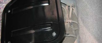
Where is the phase sensor located?
The phase sensor is located on the engine on the air filter side, next to the cylinder head
Pay attention to the picture:
Signs of a faulty phase sensor
If you have the following symptoms, then the phase sensor (df) is most likely faulty.
- When starting the engine, the starter spins for 3-4 seconds, then the engine starts and the check engine lights up. In this case, during startup, the computer waits for readings from the phase sensor, does not wait and switches to engine operating mode relying on the ignition system (according to DPKV).
- Increased gasoline consumption. (Also read: Reasons for high fuel consumption on VAZ).
- Self-diagnosis mode failures.
- Reduced engine dynamics. (the reason may also be the mass air flow sensor and low engine compression).
Diagnostics on an eight-valve engine
Please note that sensors for 8 and 16 valve engines are not interchangeable. Therefore, when purchasing, pay attention to this nuance. To diagnose phase sensors, you must perform the following manipulations:
- Connect a 13.5 Volt constant voltage source to contact “E”.
- There should be a voltage of 0.9 V at pin “B”.
- After bringing a metal object to the active part of the device, the voltage will decrease to 0.4 V.
- If you remove the metal device, the voltage will return to 0.9 V.
Replacing the phase sensor on a Lada Kalina with your own hands
First of all, a little about the tools that will be needed to perform this type of repair. Fortunately, here you can get by with just a 10mm wrench. But it is best to use a socket with a crank, or even more conveniently, a ratchet. It will just be quite inconvenient to do this with a regular key.
First, it’s worth showing clearly where all this is located:
So, first you will need to disconnect the power plug, after first squeezing the plastic latch and lifting it up a little:
Then use a ratchet to unscrew the bolt securing the Kalina phase sensor:
And now you can freely remove it by pulling it towards the windshield:
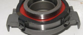
And this is what this part looks like when removed from the car:
After this, we replace the camshaft sensor and put the new one in its original place. There are absolutely no difficulties during the work process.
Its retail price ranges from 250 to 300 rubles, depending on where you buy it. Of course, this part fails quite rarely on Kalina, but still, these instructions will not hurt anyone.
About the so-called phase sensor on Kalina with 8 cells. 1.6 liter engine. Mileage 180 thousand. The engine is in perfect order. The signal indicating a malfunction of this particular sensor came on (the tester did not detect any more problems). First, CHECK went out after 10-15-20 minutes. drive. Then this time extended to half an hour, an hour. But still - it went out. Now it doesn't go out at all. I've been driving like this for about two to three months. I just did the diagnostics yesterday. Why ? The car has moved! The dynamics have clearly improved in all (.) modes. Fuel consumption decreased from 8.3 to 8.0 liters. The driving mode is standard and does not change from year to year. It is clear that it is now closer to summer, and consumption should decrease. But according to the physics of the matter, if the dynamics can improve, it is really due to an increase in fuel consumption. Reference: the average (multi-month) consumption has never fallen below 8 liters. What kind of standby modes are these that, in fact, seem to be better than the standard one? A friend, an excellent motor mechanic, albeit on marine diesel engines, suggested that due to the lack of afterburning (or whatever) exhaust in the cat. neutralizer - because the standard one has fallen apart, and naturally there is an empty collector in its place - the engine is well fed, everything is good, and everything that it doesn’t need goes straight into the atmosphere, without any extra hassle. Diagnostics does not show a malfunction of the lambda probe. He is the only one in the state, naturally on site. Straight up, miracles. Or would you say, replace this sensor? Should I go even better? But I repeat, the driving mode is absolutely standard and less than 8 liters. Over the 10 years of operation, the display showed very rarely, and not for long.
I have a similar situation, the consumption decreased slightly after turning off the phase sensor, have you figured out the reason?
I have the following question, the phase sensor cracked, I changed it. I didn’t even drive two thousand, the engine fault light came on again, I connected the diagnostic connector, the phase sensor died again. Same problem with the speed sensor. What could be the reason for such a misfortune?
My speed sensor goes off when I brake. maybe that's the problem
I have a Kalina sedan produced in 2006. When the ignition is turned on, the check engine light does not light up, the fuel pump does not pump, after which the immobilizer lamp lights up on the instrument panel, the car does not start! I take out the pump fuse and put it back into the ignition relay and I hear a crackling noise and then the car starts! Tell me, what could it be?
Check the ECU. And if you haven’t moved it from under the stove, be sure to do so. I had such a problem that the check light does not light up, the starter does not even try to turn. It turned out that the ECU was flooded. Drying is not an option - I had to get a new one. I hope that I could be wrong and that you have something simpler.
Using a phase sensor, you can track the position of the camshaft. It is not installed in carburetor engines; the first copies of injection systems did not have them either. But it can be found in almost all engines with 16 valves. Eight-valve engines are equipped with such devices only if they comply with Euro-3 toxicity standards and have phased or sequentially distributed injection of the fuel mixture. The mass introduction of these devices began around 2004 on engines produced by VAZ.
Mass air flow sensor Lada Granta
This element is located near the air filter; its main task is to estimate the amount of air entering the engine. Based on the information received from the mass air flow sensor, the ECU determines the fuel volume that is necessary to maintain the stoichiometric ratio between fuel and air for the engine to operate within the specified parameters.
The mass air flow sensor on the Lada Granta is located next to the air filter, right between it and the air falling sleeve. It should also be noted that this sensor is no longer installed on modern VAZ engines. The catalog number of the described element on Grants is 11180-1130010-00.
If the mass air flow sensor breaks down, the system stores the error code in its memory, after which the “Check Engine” lights up. Then the controller replaces the readings of the broken device with fixed temperature values. Signs of failure of this element are different, the most common include:
- increased fuel consumption;
- problems when starting the engine;
- disappearance of cravings;
- instability of speed.
Design, functional features and typical malfunctions of the VAZ 2110 phase sensor
Constant modernization in the field of road transport ensures technical improvement of its internal filling. The functioning of modern technology is impossible without the presence of a variety of measuring, signaling, adjustment and monitoring devices capable of converting the value under study into a signal suitable for use.
The phase sensor (DPRV) on the VAZ 2110 is one of the most critical elements that ensures optimal operation of the internal combustion engine. Its main purpose is to analyze the angular position of the camshaft in a certain time period. The information received from it is needed for the operation of the ignition and fuel injection mechanisms. Having this data, the car ensures coordinated operation of the camshaft, taking into account the placement of the cylinders in the engine, which allows the supply of gasoline to a specific cylinder and ignition of the fuel-air mixture.
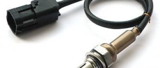
Oxygen concentration sensor (lambda probe) Lada Granta
This device is intended to assess the remaining unburnt fuel, and also estimates the amount of oxygen contained in the vehicle exhaust. The catalog number of the lambda probe on Grants is 21074-3850010-00.
The signal from the oxygen concentration sensor on the Lada Granta is used by the control system to ensure the optimal proportion between air and gasoline in the combustion chamber; based on the information received from the DC, the ECU makes corrections in the composition of the mixture of air and gasoline. The lambda probe is installed in the Granta intake system, or more precisely, in the catalytic converter.
The main signs of failure of the described element include:
- significantly increased fuel consumption;
- floating speed of an idling engine;
- problems when accelerating a car.
Checking the electrical circuit
Malfunctions in the cooling circuit system are not always associated with faulty sensors; in 70% of cases, the problem is a violation of the integrity of the wires. On Kalina, the block often suffers; the thin plastic at the entrance to the block rots and cracks. After disconnecting the pads from the sensors, the throughput of the circuits is always checked before dismantling the latter.
- The ignition is turned off and the block is removed from the sensor.
- The tester probe (multimeter) is connected to output “B” of the block, the second tester probe is located at ground.
- The ignition turns on.
- The monitor should display a voltage in the range of 4.8–5.2 V. These are indicators of the complete circuit.
- Similarly, the performance of the circuit is checked by resistance. The tester probe is connected to terminal “A” on the block, the second one is connected to the ground of the car. The operating circuit will show a resistance of less than 1 ohm.
If the voltage does not correspond to the operating voltage, then the circuit is checked for an open circuit. The tester probe is connected to terminal “B” on the block and terminal “39” on the controller; if the voltage is normal, then there is a malfunction in the control unit.
The cooling circuit of the Lada Kalina engine is equipped with two temperature sensors, the correct operation of which determines the performance of the engine and its service life. You can diagnose and replace the control elements yourself; it will take about an hour of time and a little skill.
Recommendations for starter maintenance
Adhere to the technical inspection schedules established by the manufacturer - every 15,000 km. Buy original parts and components at official points of sale.
Use the services of certified workshops for diagnostics and repairs. Remember that unprofessional intervention in the operation of the car is more likely to harm than help.
Don't skimp on consumables. Check the catalog numbers with the actual data specified in the instruction manual.
Keep the control unit active while starting the engine for no longer than 15 seconds, then 30 seconds. break. After starting the engine, release the key from the ignition switch as soon as possible. Excessive retention eats up the teeth on the drive shaft and flywheel.
Purpose, location, principle of operation
If you need to find where the crankshaft sensor is located on a Lada Kalina for 8 cylinders, pay attention to the left side of the cylinder head. The controller is located there
The main function of the part is to control the location of the crankshaft relative to the angular part of the gas distribution mechanism.
The functions of the electromagnetic sensor include synchronizing the operation of the injectors and ignition in the automotive system responsible for fuel injection.
When the necessary information is received and analyzed by the control mechanism, the mixture is injected and the ignition is adjusted. The spark hits the spark plug at the moment when the exhaust gases are compressed and started. As you can see, the operation of the entire system depends on the correct performance of its functions by the crankshaft sensor. This is the main link, and without its correct operation the entire injection system cannot function.
Despite the difference between the 8-valve Lada Kalina engine and a similar 16-valve engine, a controller for an 8-valve is often installed on the latter; it is capable of ensuring proper operation of this engine as well. The exception is the sensor, which does not have a slot for the signal disk - it cannot be installed on an engine with sixteen valves.
The role of electromagnetic valves in the operation of the timing system
The power unit of the Peugeot 308 has two phase valves and the 307 has one phase regulator, which is installed in a toothed pulley. Structurally, the pulley has two main parts: an impeller equipped with a blade and a cylinder with a chamber. When the established conditions are reached, the electronic control system sends a signal to the phase solenoid valve. When opened, the valve provides oil supply under a certain pressure through the central channel located on the camshaft. Oil enters through holes in the central part of the impeller and the mechanism that lifts the plunger.
Due to the pressure under which the oil is supplied, the plunger moves upward and the impeller is released. Due to this, the impeller and the phase control device rotate in the direction of delaying the operation of the intake valves. After removing the voltage from the solenoid valve, the blade and impeller return to their original position, and the plunger locks the entire system in a state of minimal lag.
The valve is responsible for ensuring the flow of oil to the phase control device. After turning off the control potential on the electromagnetic device, the phase regulator moves the camshaft to a state with the least lag, thereby ensuring maximum torque at low speeds.
On Peugeot 307 and 308, phase regulators mounted on camshafts function normally if the following parameters are met:
- at crankshaft speeds above 1500 rpm;
- when the pressure in the intake pipe reaches over 500 mbar;
- at antifreeze temperatures above 30 degrees.
The ECU is involved in changing the valve timing, which reads the location of the crankshaft and camshaft, the temperature indicators of the antifreeze, as well as the speed of the vehicle. The ranges for adjusting the rotation angles and camshaft at idle speed vary from +5 to -5, and with a sharp increase in speed, from 0 to 30 degrees.
Vote, did you like the article?
Replacing the device
You can buy an oxygen sensor in auto stores, directly from a car dealer and on the Internet. But in order to correctly carry out the replacement, you need to know a number of important parameters:
- heater resistance value;
- probe electrical circuit diagram;
- catalog number of your sensor.
There are also many replacement options, but among them there are fakes. Typically, car enthusiasts replace a failed lambda probe with the same one, but from a different manufacturer. A wide selection of sensors is provided by the American company Walker, which has a branch in Russia. Lambda probes manufactured by Bosch are interchangeable with zirconium sensors of similar structure.
Please note that a non-heated sensor can be replaced with a heated sensor. Not the other way around
Before installing a new oxygen sensor, it is necessary to remove the terminals from the battery and apply graphite lubricant to the device itself (that is, to its threads). We install the lambda in its original place, start the engine and wait until the sensor warms up to operating temperature. As it warms up, we monitor the signal output voltage with a voltmeter.
Sometimes, when tuning the exhaust system, it becomes necessary to disable or remove the second lambda (in front of the catalyst). Moreover, the composition of the mixture does not depend on its operation, since it is controlled by the first sensor located in the intake manifold. There are different ways to do this. You can do the so-called decoy. To do this, the first lambda is removed and its wires are extended. The second sensor is also removed, the wires are exposed and they are connected.
In one of the wires the voltage will be about 4 W; it is to this wire that you need to solder a resistor with a resistance of 1 Ohm. It is also necessary to solder a capacitor with a capacity of 2.2 F, after which the 1st sensor is connected to the converted exhaust, and the second one simply remains dangling in its original place. This method usually saves money because it eliminates the need to reflash the ECU, which is expensive.
However, some drivers still advise reflashing. But since replacing the exhaust does not make it possible to leave the catalyst, there are few options in this situation. There is another way - installing an oxygen sensor emulator. Either reprogram the Euro-3 engine to Euro-2 for a lot of money, or solder the blende yourself for a long and painful time.
The emulator is a device precisely designed to be compatible with the brains of the engine. Using it, you will not damage the lambda in the intake manifold and will not make things worse for your iron horse. Otherwise, the ECU simply will not allow the engine to operate normally, since it will stop receiving data from the catalyst and diagnostic sensor (the probe has been removed). This is how the oxygen sensor on a Lada Kalina is repaired. Good luck!
Coolant temperature sensor
The DTOZH in Grant is located in the thermostat block and serves to read the coolant temperature. The sensor is also responsible for the operation of the engine cooling fan and for the presence of warm-up engine speed. When starting the engine, you will notice that if the DTO is in good working order, the speed is slightly higher than the working idle speed; as soon as the internal combustion engine warms up, the speed returns to normal.
Symptoms of malfunction:
- There are no increased speeds to warm up the internal combustion engine;
- The engine cooling fan does not work;
This is interesting: Removing the fuel rail and injectors of VAZ 11183, VAZ 21116 and VAZ 11186 Lada Granta engines
Replacing the sensor
To personally change the sensor on a Lada Kalina, you need to take: the 10th key, a new consumable, a rag, a Phillips screwdriver and an additional light source. Then follow the instructions:
- Open the hood.
- Find the controller to the right of the filler neck.
- Using a screwdriver, unclip the conductor block.
- Use the tenth key to unscrew the fasteners.
- Remove the controller and carry out troubleshooting to seat the consumable.
- Clear space for a new consumable, insert a new device.
- Put on the block with wires.
The controller replacement is complete. All that remains is to start the engine and check how the new equipment works. If you follow the regulations for installing a new consumable, then on average it will last 90,000 kilometers. All manipulations will require 1 hour. It is better not to try to make the procedure faster to avoid breaking the plastic clamps.
As a result, the phase sensor on the Lada Kalina is a necessary part for normal engine operation. It rarely breaks, but you need to know the signs and causes of the breakdown, and also remember the step-by-step instructions for fixing it.
Instructions for replacing the regulator
The crankshaft DP is located on the oil pump cover near the camshaft drive. To replace it, you need to buy a new device according to the markings on the old product.
1. DPKV for replacement
2. Tool - head with knob
3. Location of the DPKV
The replacement procedure is simple:
- Remove the negative terminal from the battery.
- We disconnect the block with wires from the DPKV by bending the lock.
- After this, use a “10” key to unscrew the fastening bolt.
- Now it is fashionable to remove the regulator.
- The installation site should be cleaned of dirt and a new product can be installed.
- Next, the fastening bolt is screwed in and the wires are connected.
How to check the phase sensor
Checking the functionality of the internal combustion engine phase sensor is carried out using a diagnostic tool, as well as using an electronic multimeter capable of operating in DC voltage measurement mode. We will discuss an example of a test for phase sensors of a VAZ-2114 car. On models with a 16-valve engine, a sensor model 21120-3706040 is installed, and on 8-valve engines - 21110-3706040.
First of all, before diagnostics, the sensors must be removed from their mounting location. After this, you need to visually inspect the DF housing, as well as its contacts and terminal block. If there is dirt and/or debris on the contacts, it must be removed with alcohol or gasoline.
To check the sensor of the 8-valve engine 21110-3706040, it must be connected to a battery and an electronic multimeter according to the diagram shown in the figure.
Next, the verification algorithm will be as follows:
- Set the supply voltage to +13.5±0.5 Volts (you can use a regular car battery for power supply).
- In this case, the voltage between the signal wire and ground must be at least 90% of the supply (that is, 0.9V). If it is lower, and even more so equal or close to zero, then the sensor is faulty.
- Bring a steel plate to the end of the sensor (with which it is directed towards the camshaft reference).
- If the sensor is working properly, then the voltage between the signal wire and ground should be no more than 0.4 Volts. If more, it means the sensor is faulty.
- Remove the steel plate from the end of the sensor, the voltage on the signal wire should again return to the original 90% of the supply voltage.
To check the phase sensor of a 16-valve engine 21120-3706040, it must be connected to a power supply and a multimeter according to the diagram shown in the second figure.
To test the corresponding phase sensor, you will need a metal piece with a width of at least 20 mm, a length of at least 80 mm and a thickness of 0.5 mm. The verification algorithm will be similar, however, with other voltage values:
- Set the supply voltage on the sensor to +13.5±0.5 Volts.
- In this case, if the sensor is working properly, then the voltage between the signal wire and ground should not exceed 0.4 Volts.
- Place a pre-prepared steel piece into the sensor slot where the camshaft reference is placed.
- If the sensor is working properly, then the voltage on the signal wire should be at least 90% of the supply voltage.
- Remove the plate from the sensor, and the voltage should again drop to a value of no more than 0.4 Volts.
In principle, such checks can be performed without removing the sensor from its mounting location. However, to inspect it, it is better to remove it. Often, when checking a sensor, it makes sense to check the integrity of the wires, as well as the quality of the contacts. For example, there are cases when the chip does not hold the contact tightly, which is why the sensor does not receive a signal to the electronic control unit. Also, if possible, it is advisable to “ring” the wires going from the sensor to the ECU and to the relay (power wire).
In addition to checking with a multimeter, you need to check for relevant sensor errors using a diagnostic tool. If such errors are detected for the first time, you can try to reset them using software, or simply by disconnecting the negative terminal of the battery for a few seconds. If the error appears again, additional diagnostics are needed using the above algorithms.
Typical phase sensor errors:
- P0340 - no camshaft position sensor signal;
- P0341 - valve timing does not coincide with the compression/intake strokes of the cylinder-piston group;
- P0342 - the signal level in the electrical circuit of the DPRV is too low (detected when there is a short to ground);
- P0343 - the signal level from the meter exceeds the norm (usually occurs when the wiring is broken);
- P0339 - an intermittent signal is received from the sensor.
Thus, if these errors are detected, it is advisable to perform additional diagnostics as quickly as possible so that the engine operates in optimal operating mode.
Meter design and location
The operating principle of the DPRV is based on the Hall effect - the sensor reacts to the approach of a metal mass by changing the voltage on the signal wire. The design of the device is similar to another element - the crankshaft position detector. Inside the plastic case there is a coil where the 12 V on-board voltage is constantly supplied.
The meter is installed on the engine cylinder head in close proximity to the camshaft. The latter is equipped with a special plate or gear, whose rotation affects the DPRV. The work algorithm looks like this:
- After turning on the ignition and starting the engine, a supply voltage of 12 V is supplied to the sensor. Through the third signal wire, the element supplies the controller with a voltage of 90–95% of the original one.
- When the protrusion on the rotating part of the camshaft passes next to the DPRV housing, the voltage at the signal contact drops to 0.2–0.4 volts, depending on the design of the device and the vehicle model.
- When the voltage drops, the electronic unit clearly “sees” the valve timing, promptly supplies the fuel mixture to the engine cylinders and directs the spark discharge to the desired spark plug.
When the meter is faulty, the electronics are unable to control the operation of the gas distribution mechanism. In such cases, the control unit goes into error and is guided by the signals of other meters. Spark generation and fuel supply are adjusted according to the programmed program, which affects the operation of the power unit.
When the meter is faulty, the electronics are unable to control the operation of the gas distribution mechanism. In such cases, the control unit goes into error and is guided by the signals of other meters. Spark generation and fuel supply are adjusted according to the programmed program, which affects the operation of the power unit.
Phase sensor (camshaft position)
You will find this part on the cylinder head on the left side. The operating principle is quite simple. There is a special pin on the camshaft itself. When it passes by the sensor, but sends a signal to it. This moment corresponds to compression of the piston of the first cylinder.
The controller determines the camshaft angle. This is important information for machine systems and sensor failure has certain consequences. The information is sent to the vehicle's ECU, which uses it to control the ignition and fuel supply to each cylinder.
In what situations is replacement required?
If this part fails, you will see a “Check” indicator on the vehicle’s instrument panel. This is how the ECU signals the driver that the engine needs to be checked. At the same time, the fuel supply pattern changes - it goes to all cylinders simultaneously and, as a result, consumption increases.
The cause of the breakdown may be mechanical damage, as well as other things. There is no point in trying to repair the old unit itself - it costs little and you will waste more nerves and time.
In the video below you will find instructions for replacing this part (the author of the video is Alexandr V).
Replacement instructions
To replace the camshaft sensor, you only need a "10" key. It is better to use a socket with a collar or a ratchet. It will be inconvenient to work with a regular key, although it is still quite possible.
The dismantling and installation procedure is as follows:
- First, disconnect the block with wires by pressing the latch and slightly pulling it up;
- now, using the key, unscrew the part itself;
- it can be pulled out by slightly pulling towards the windshield;
- installation is carried out in the reverse order of steps.
There are no difficulties in this process, but be careful not to damage both the block with wires and the connector for the controller itself on the cylinder block.
What does the performance of the DPRV depend on?
The performance of the DPRV depends on the temperature conditions. Overheating will damage it. The sensor will not work if the wires through which it transmits and receives the signal are faulty, or the reference point is broken. Damage or contamination of the sensor itself plays an important role. Also, under difficult operating conditions (off-road driving, cargo transportation), the sensor may move or, even worse, a short circuit may occur. In order to eliminate sensor failure at the most inopportune moment, diagnose it and replace it after 4-5 years.
Main sensor malfunctions and their causes
The main symptoms of a malfunctioning camshaft sensor:
- the “check engine” signal comes on and driving dynamics deteriorate;
- the number of revolutions increases or decreases independently;
- a warm engine is unstable at idle speed;
- under dynamic loads, detonation occurs in the power plant;
- higher fuel consumption;
- The engine does not start.
If you notice such symptoms, check how the camshaft sensor is working. It may have failed and needs to be replaced. The causes of sensor malfunction can be: failure of the disk with reference points, displacement of the DPRV installation, short circuit inside the device, overheating of the motor.
How to check the camshaft sensor
Before checking the camshaft sensor with a tester, you need to visually inspect the sensor housing and gear rotor for damage or the presence of metal shavings. This may also be the reason for its malfunction.
Diagnostic tool
To check the camshaft sensor you will need: a multimeter/tester, pliers and a screwdriver. The multimeter/tester will guide you to perform a detailed test of the device. It will show exactly what is wrong with the sensor itself or the wiring.
Test scheme
Before starting to diagnose the sensor, examine the connector which should have: positive, negative contacts and a contact for signal transmission.
1. Turn the ignition on and check the camshaft sensor with a multimeter. Connect the tester ground to the engine ground. The measurement must correspond to the voltage readings at the battery terminals. If the readings do not match, then the sensor's power supply circuit has failed.
2. After this, measure the voltage at the sensor ground in a similar way. The voltage should be zero.
3. Connect the positive and negative wires of the camshaft sensor. Connect the middle contact through the tester. Thus, we connect one wire of the multimeter to the signal terminal of our sensor, the other needs to be powered to the input to the control system.
4. After this, crank the engine with the starter. If the sensor is working, it will show a voltage from 0.4 to 5 volts. If the values are different, the sensor should be replaced.
If, after checking, you find the cause of the breakdown in the sensor itself, do not delay replacing it. Without it, the engine will work, but in emergency mode, fuel consumption will increase significantly, since fuel is now supplied to all cylinders simultaneously.
Power windows on grant
Rice. 3. Procedure for tightening the camshaft bearing housing nuts
We finally tighten the nuts to the prescribed torque (see “Appendices”) in the same sequence.
After tightening the nuts, carefully remove any remaining sealant squeezed out of the gaps. Check the clearances in the valve mechanism. We press in a new camshaft oil seal (see “Replacing the camshaft oil seal”). Further assembly is carried out in reverse order.
The camshaft sensor Kalina 8 valves becomes unusable from time to time. This can happen for various reasons, but the result is the same - the part needs to be replaced. The situation is similar with the crankshaft position sensor. You will learn in the article how to dismantle old and install new elements of a car of this type.
Clutch and brake sensors Lada Granta
Thanks to the signals sent by these sensors, the controller receives information about whether the corresponding pedals (clutch and brake) are pressed or not pressed. Both elements are located in the area of the pedal assembly.
The clutch sensor is a stabilizer, which from a design point of view is a limit switch. Its failure will lead to surges in speed and unstable operation of the engine. The car owner will be informed about the breakdown by the illuminated Check Engine; in addition, problems will appear with sudden jumps in speed during gear shifts.
The above is evidence of the following malfunctions:
- the height of the pedal is incorrectly positioned relative to the floor;
- clutch sensor is faulty;
- there are disturbances in the circuit.
They also began installing brake pedal sensors on Grants. However, many owners of this car, after only using it for a short time, notice error P0504, indicating a breakdown of this sensor. In most of these cases, the above error occurs due to incorrect adjustment of the element. For this reason, car owners report symptoms such as:
- unstable engine operation;
- instability of speed.
Functionally, the brake pedal sensor is responsible for the position of the pedal itself and turning off the brake lights. In addition to its misalignment, problems with this part can be caused by a breakdown of the spring located inside the sensor.
The presence of a malfunction will be confirmed to the owner by the illuminated Check Engine and the already mentioned error P0504. This error is a consequence of a breakdown of either the sensor itself or its wiring. In addition, the cause of the error is often the misalignment already mentioned above. The new element will cost the car enthusiast approximately 180 rubles.