Published: 10/20/2020
- Repair
- Methods for checking the ignition module of a VAZ 2114
- Repair
- How to disassemble the ignition module of a VAZ 2110
- Ignition module repair
- Version of the module on the 8-valve VAZ-2112
- We disassemble the design of the ignition module of a modern injector
- Checking module power
- Possible reasons for failure of the ignition module
- Diagram of the correct connection of wires to the ignition module
- Connection diagram
- VAZ 2115 ignition module, description and malfunctions
Pinout, connection diagram and check of the VAZ ignition coil
Today we will look at the design and diagrams of ignition systems for VAZ cars of all major models. Since carburetor versions of VAZ are practically history, we will dwell in detail on the ignition systems of injection cars. Their ignition system is based on an electronic ignition module. We also recommend that you carefully consider the choice of spark plugs and the quality of high-voltage wires, because the quality of the spark and, accordingly, the operation of the ignition system as a whole will depend on them. The information is intended as a reference guide for self-repairing a car.
Priora, 2170-2173
The Lada Priora is equipped with the same ignition coils as the Kalina. The coil is marked 2112-3705010-12. Just as in the case of Kalina, Priora is equipped only with injection engines, so carburetor ignition coils or “bobbins” cannot be installed on the car.
To summarize, it is worth saying that when choosing an ignition coil for a car, it is necessary to take into account the marking of the part, its compatibility with a particular model of the domestic automobile industry. Despite the high interchangeability, attention is also paid to the overall dimensions of the part and the type of fastening in the engine compartment of the car. You can purchase coils or ignition modules for domestic “classics”, “Samara” and “Sputniks” in our online store with a few clicks of a computer mouse.
Pinout and diagram of the VAZ ignition coil
Pinout of ignition coil modules for various car models of the VAZ family:
Ignition VAZ 2101
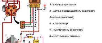
1 – generator; 2 – ignition switch; 3 – ignition distributor; 4 – breaker cam; 5 – spark plugs; 6 – ignition coil; 7 – battery.
Ignition VAZ 2106
1 – ignition switch; 2 – fuse and relay block; 3 – EPHH control unit; 4 – generator; 5 – solenoid valve; 6 – microswitch; 7 – spark plugs; 8 – ignition distributor; 9 – ignition coil; 10 – battery.
Ignition VAZ 2108, 2109
Ignition VAZ 2110
Ignition VAZ 2111
Ignition VAZ 2112
Ignition VAZ 2114
Diagram of a non-contact ignition system: 1 – non-contact sensor; 2 – ignition distributor sensor; 3 – spark plugs; 4 – switch; 5 – ignition coil; 6 – mounting block; 7 – ignition relay; 8 – ignition switch.
High-voltage wires VAZ 2115: Connection, replacement, location
Automotive high-voltage (HV) wires play an important role for internal combustion engines, since they help transmit high current from the ignition coil to the spark plugs.
The serviceability and efficiency of the wires determines the timeliness and intensity of ignition of the fuel-air mixture, and therefore the correct and uninterrupted operation of the engine.
Despite their simplicity, wires have many different “sores” and can cause a lot of troubles to their owner, which in one way or another will affect his nerves and pocket.
Table of contents
ConnectionReplacementLocation
Connection
The order of connecting high-voltage wires must be strictly sequential, since each cylinder of the engine corresponds to a specific socket on the ignition module. Considering that there is a numbering of the sockets on the ignition module body, the risk of confusing anything is minimal.
The procedure for connecting high-voltage wires of the VAZ 2114 injection type depends on the year of manufacture of your car. Fourteen cars before 2004 had 4-pin ignition modules installed, and cars after 2004 had 3-pin coils.
The connection diagram for VAZ 2114 high-voltage wires to the ignition module (until 2004) is as follows:
Connection diagram for VAZ-2114 with ignition coils (after 2004):
To correctly install high-voltage wires on the VAZ 2114, follow the following algorithm of actions:
— Turn off the ignition. Open the hood and remove the power terminals from the battery;
— We remove the old GDPs from the mounting sockets on the module and cylinders;
— We remember the location of the high-voltage wires of the VAZ 2114 and connect new GDPs according to the diagram. Before replacing, it would not be amiss to draw this very diagram by hand on paper so as not to confuse anything;
— We connect power to the battery and, to check whether we did everything correctly, start the engine.
When installing the wiring, do not try to connect individual air intakes to each other with plastic clamps; to do this, you must use the comb holder that comes with them. A thin clamp can easily wear through the insulating coating. Also make sure that the GDP does not bend.
Connecting armored wires on VAZ 2115 and 2113 is carried out in a similar way.
Replacement
How to remove high-voltage wires?
Turn off the ignition Open the hood
We pull out the wires from the ignition module and from the engine.
How to connect high voltage wires?
The BB wires must be connected in a certain order. Each wire goes to a specific cylinder and to a specific connector in the ignition module (ignition coil). There are markings both on the wires and on the ignition module. But without removing the module, the markings cannot be seen, so see the photo below.
Connection diagram for high-voltage wires:
Cylinder numbering from left to right. Ignition module numbering: first cylinder - lower left compartment of the ignition module
Second cylinder - upper left compartment
The third cylinder is the upper right,
The fourth cylinder is the lower right compartment of the ignition module.
Location
Incorrect installation and location of high-voltage wires can lead to a spark jumping from wire to wire or to ground, which, in turn, can lead to misfires and a decrease in the crankshaft speed when the car is moving at high speed.
Therefore, install the high voltage wires properly as shown in the pictures above.
Examination
EXECUTION ORDER
Disconnect the high-voltage wires from the spark plugs and ignition coils. Clean and check the integrity of the insulation of high-voltage wires. Check the internal contact surfaces of high-voltage wires for corrosion or carbon deposits.
Use an ohmmeter to measure the resistance of the high-voltage wires.
| Cylinder |
| Length, mm |
| Resistance (BOUGI), Ohm |
| Resistance (R16AIPS), Ohm |
The resistance of the high voltage wire should not exceed 10,000 ohms, otherwise replace the wire.
How to check the ignition coil of a VAZ
If the ignition coil is faulty, the engine will not start. A characteristic sign of a faulty coil is its increased temperature when the ignition is turned off. This is easy to determine by touch.
Signs of a faulty ignition module may include the following:
- hesitant engine starting or failure to start;
- failures during sudden changes in speed;
- high fuel consumption;
- two cylinders do not work, the engine is feverish;
- lack of dynamics;
- a sharp drop in power;
- drop in power and thrust after warming up.
These symptoms may not only be caused by the ignition module. To determine the malfunction, it is enough to spend a few minutes diagnosing spark plugs, high-voltage wires and caps. This will eliminate the remaining elements of the ignition system and make sure that it is the ignition module that is faulty.
Checking the ignition coil is performed in one of 2 ways. The simplest one is to remove the central wire from the breaker-distributor, bring it to the motor housing and turn it with the starter, and a running spark should appear. After this, we check the energy supply to a separate spark plug, for which we unscrew the working spark plug, bring its contact to ground and attempt to start the engine. In this case, the spark should come from the wire to ground. If it is absent, the reason will be a malfunction of a system element such as the ignition coil.
To check the module in the second way, we only need a multimeter, then follow the step-by-step instructions:
- We check the power supply and the presence of pulses supplied from the ECU. We check the power between the central terminal (15) of the wire block connected to the module and the engine ground. When the ignition is on, the voltage should not be less than 12 V. Otherwise, either the battery is dead or the ECU does not work.
- We check the pulses from the ECU on the wiring block. We install one tester probe on connector 15, the second on the far right, then on the far left. The assistant cranks the engine with the starter, and at this time we record short-term voltage surges with a tester. If there are no impulses from the ECU, it is he who is to blame.
- We check the resistance on the secondary windings of the coils. We put the tester in resistance measurement mode and measure it at the high-voltage terminals of the module cover. Between pins 1 and 4 and pins 2-3, the resistance should be 5.4 kOhm. Otherwise, the module must be replaced.
- We check the resistance of the primary windings between contacts 15 and the rightmost, then the leftmost terminals. Nominal - 0.5 Ohm. Deviation is not allowed.
- Check the module for a short circuit. In ohmmeter mode, install one multimeter probe on the central terminal, the second on the metal body. There shouldn't be any resistance. If the device detects at least some resistance (other than unity or infinity), the module must be replaced.
Contactless (electronic) ignition, carburetor
Many car owners are switching to a more accurate (electronic) type of ignition. To adjust the device yourself, you need to have skills in working with the electrical part of a car. If you do not have sufficient knowledge, entrust the work to experienced specialists.
Prepare the instrument for tuning. You will need keys (for “eight”, “ten” and “thirteen”), a Phillips screwdriver, a drill and a pair of self-tapping screws.
Pre-install the contactless system itself, consisting of the following elements:
- Trambler. Start by replacing the distributor by lifting the cover of the latter (this is how you gain access to the “slider”). Place the slider in a position that can be easily adjusted during installation. It is desirable that the notch be on the block opposite the middle mark of the device scale.
Use a “thirteen” wrench to tighten the fastening nut, and then dismantle the assembly. Now disconnect the central wire connecting the coil and the distributor. Mount the non-contact type sensor and adjust the slider taking into account the previously made mark. Align the distributor body along the notches. Replace the cover and return the wires to their place.
- Coil. In the next step, move on to the ignition coil. Take the eight key and twist the wires that are connected to the device. Now use the key to “ten” to push the assembly away from the car body.
Install the new coil taking into account the position of contacts “B” and “K”.
Fix the coil and connect the discarded and new wires to the contact group. Pay attention to the colors of the latter (as a rule, they are identical for the old and new devices). Connect the brown wire to terminal “K” and the blue wire to “B”. Now connect the center wire.
- Switch. Start by choosing a location for this node. In the "seven" the best point for installation is between the headlight on the left side and the washer. In this area there is a flat area on which the device is placed. To begin, lean the switch and mark the mounting locations. After this, screw in the screws. Do not rush to tighten the second fastener - place a black wire under it.
As soon as the described work is completed, check the quality of the connection of the wiring elements and start the engine. The next stage is installing the ignition of the VAZ-2107, which will be discussed below.
Connecting and replacing VAZ short circuit
The procedure for removing and installing the ignition coil on old VAZ models:
- First, disconnect the central high-voltage wire leading to the distributor (ignition distributor).
- Disconnect all power wires from the coil contacts. Since they are fastened with nuts, you will need an 8 wrench for this.
- If you don’t know which wires to connect to which connector later, it’s better to immediately remember or mark them somehow, so that later during installation you can connect them correctly.
- Unscrew the coil housing. It is attached to a clamp (clamp), which is pressed to the car body with two nuts.
- After the work has been done, you can remove the ignition coil and replace it if necessary.
For new type VAZ cars:
- We remove the “minus terminal” from the battery.
- Remove the top protective cover of the engine. If the engine volume is 1.5 liters, then this part is missing and this step is skipped.
- We remove the high-voltage wires from the coil.
- Now, using a 13mm wrench, unscrew the two fasteners.
- Using a 17mm wrench, loosen one bolt securing the coil.
- We take out the module.
- Use a hexagon to unscrew the coil from the holder.
- Assembly is carried out in reverse order.
Particular attention should be paid to the connection, since high-voltage wires must be located in the strict order provided for by the design. If this is not done, the car will stall or the engine may not start at all.
Replacing the ignition coil on a VAZ is quite simple. Even a novice motorist can do this in his garage, and if everything seems too complicated, contact a car service center. Particular attention should be paid to the choice of product, since this will determine how well the engine and ignition system will work.
Tuning on carburetor modifications of the VAZ 2107
All old textbooks on servicing classic Zhiguli models describe a method for setting the moment of spark formation using a light bulb, although experienced motorists can easily do without it. You will understand why this happens as you read this material, but for beginners it will be useful to familiarize yourself with the old proven technique.
To correctly set the ignition of the “seven”, you need to ensure that the following conditions are met simultaneously:
- the notch on the crankshaft pulley is opposite the long mark on the timing cover;
- in this case, the round mark marked on the camshaft chain drive gear coincides with the boss on its body;
- the piston of the 4th cylinder has completed the compression stroke and is at top dead center;
- the contacts inside the distributor are open;
- The movable contact of the slider faces the fixed contact on the distributor cover, where the wire from the spark plug of the 4th cylinder is connected.
Note. On non-contact systems, at this moment the Hall sensor sends a signal to the switch to break the low voltage electrical circuit, which leads to the appearance of a high voltage pulse on the wire leading to the spark plug of the 4th cylinder.
The diagram shows what happens in the cylinders when the marks are aligned
The light bulb is used to control the ignition timing, for which it must be connected with one wire to the “K” contact of the high-voltage coil, and with the second to the vehicle ground. You should know that at the same moment the piston of the first cylinder is also in the TDC position, only there the air-fuel mixture is not compressed, but exhaust gases are released after its combustion. This is why ignorant car enthusiasts often confuse the first cylinder with the fourth when installing the ignition.
Layout of marks on the timing cover
When the above actions occur simultaneously, a spark discharge occurs on the electrodes of the spark plug of the 4th cylinder, as evidenced by the flash of the connected light bulb. To achieve these conditions and set the ignition correctly, follow the instructions:
The marks must be aligned by turning the crankshaft with a wrench
Note. The instructions imply that before starting work the distributor was removed from the engine without aligning the marks.
The ignition is considered to be set correctly if, after installing the distributor cap and connecting the wires, you manage to start the engine, and then you need to adjust the timing. The non-contact system is installed in the same way, with the exception of checking the gap in the contact group due to its absence.
The mark on the camshaft gear is aligned with the boss on the body
Important point. In most cases, the ignition is set without removing the valve cover, which is why the position of the mark on the gear is not visible. You have done everything according to the instructions, but the engine does not start. This means that a spark is supplied to the 4th cylinder during the exhaust stroke, and compression at this moment occurs in the first cylinder. The problem can be solved simply:
- remove the distributor cover;
- unscrew the nut securing it;
- pull the distributor out of the socket, turn the slider exactly 180° and insert the element back;
- Press the distributor skirt with the nut and install the cover.
Advice. If the engine does not start after these steps, but begins to show signs of life, then the problem lies not in the ignition setting, but in a malfunction of one of the system elements.
Photo instructions for setting up
First of all, the marks on the pulley and timing cover are aligned
The distributor is inserted into the hole so that the slider points to the 4th cylinder The distributor skirt is pressed to the block with a 13 mm nut The gap is checked with a feeler gauge with the contacts open The gap is corrected if you unscrew the 2 screws securing the contact group The light comes on when a spark appears
We check the ignition module on the injection VAZ-2110 8 valves with our own hands
At different times, different engines were installed on the VAZ-2110 car, both carburetor and injection. However, regardless of the type of power system and the number of valves (8 or 16), all engines are assembled on the unit base of the old engine 21083 and 21093. The most progressive of these engines is the 16-valve 1.6-liter VAZ 21124 engine with a power of 89 horsepower. Today we will touch on the ignition module for 8-valve engines 2111 and 21114 (1.6 l), check its performance and find a suitable replacement for the failed module.
When should you turn on the ignition?
The first thing you should know is that there are no regulations for this operation, since the ignition timing is set or adjusted only if necessary. It may be caused by the following reasons:
- You recently purchased a “Seven” on the secondary market and are trying to “bring it to mind.”
- After engine repair, accompanied by its disassembly.
- After unscrewing or removing the main ignition distributor (distributor), regardless of the reason why this was done.
- When switching from high-octane fuel to gasoline with a lower octane number and vice versa.
- After replacing the contact group or bearing in the distributor (in cars with an old ignition system).
- mechanical with contacts. switches;
- contactless;
- controlled by an electronic unit (ECU).
Note. On VAZ 2107 vehicles equipped with an electronically controlled injector, the reason for checking the spark generation system may be the flashing of the Check Engine display on the instrument panel. True, it behaves in a similar way when a dozen more malfunctions occur. So ignition problems must first be diagnosed by contacting a service station.
In the vast majority of cases, the sparking moment is set as a result of a violation of the settings after disassembling or repairing the engine. A separate issue is the transition to high-octane gasoline, which requires ignition with greater advance, for which adjustments are being made.
It is advisable to check the timely formation of a discharge on the electrodes of the spark plugs in cases where unstable engine operation is observed, popping noises are heard in the carburetor and exhaust pipe, accompanied by an increase in fuel consumption. If you have not yet discovered the “gluttony” of the car, then pay attention to the color of the smoke; with high gasoline consumption, it is black, as is the carbon deposits on the electrodes of the spark plugs.
Types of systems
For decades, until the release of the VAZ 2107 (from 1982 to 2012), it was equipped with three types of ignition systems:
The note. The first 2 grades were placed on the “seven” of the carburetor, the latter is represented by an injector.
In the mechanical embodiment, the contacts opened by the camshaft cam open the low voltage circuit, initiating the formation of a powerful pulse in the secondary coil winding. This discharge is directed to the fuel spark plug electrodes in the cylinder, where the piston rises to top dead center (TDC) and the compression stroke is completed.
The contactless circuit works on the same principle, only the Hall sensor signals an open circuit, and its switch implements this. Therefore, the ignition settings on the “seven” carburetor are almost identical. One more thing. These are nozzle machines that have a new system that not only has the contacts, but also the distributor and any moving parts. Here, the spark torque is determined by the ECU controller by focusing on the signals from different sensors.
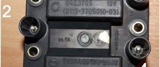
Version of the module on the 8-valve VAZ-2110
The top ten was equipped with two 8-valve engines of different sizes - 1.5 (2111) and 1.6 liters (21114). The ignition modules for these engines are different.
- The one and a half liter engine has a module with article number 2112-3705010,
- and the 1600 cc engine is equipped with module 2111-3705010.
A module for a 1.5 liter engine costs about 1500-2100, and the second one is 500 rubles cheaper.
Let's sum it up
As you can see, the VAZ 2110 ignition module is a fairly simple device consisting of contacts, coils, boards and wires. However, only contact connections can be repaired. Other elements are beyond repair and need to be replaced.
At the same time, before starting repair work, it is necessary to properly test the module. To do this, you should adhere to the general rules, and also take into account the subtleties and nuances discussed above. As a result, diagnostics of the VAZ 2110 ignition module allows you to quickly identify certain problems and eliminate problems.
Symptoms of a problem
It is extremely rare for two built-in coils to fail at once, so it is more likely to be possible to start the engine with a faulty unit. However, even an inexperienced driver will immediately suspect something is wrong. The malfunction will appear as follows:
- unstable (floating) idle speed;
- the engine has difficulty picking up speed;
- characteristic sound of the engine (triple);
- jerking when accelerating (while moving).
Operating a car with such a breakdown is possible (you can drive to a garage or car service station), but it is not advisable unless absolutely necessary.
Similar signs of unstable engine operation are possible with a number of other ignition or fuel supply faults. To differentiate possible breakdowns, the performance of the ignition unit should be determined. It would be useful to check the contacts of the wires coming to the device, as well as their integrity.
Methods for diagnosing device performance
The simplest method that will help determine the performance of the coil is to replace it with a similar working device. This is possible if there is somewhere to get it. Please note that the module must match the parameters of the device under test. If the engine with a working coil works as before the breakdown, the ignition module is definitely faulty.
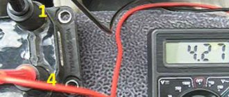
The main testing method involves using a multimeter. It consists in determining the resistance of the secondary windings of the coils built into the ignition module. The method is simple and does not require additional skills. The device does not need to be removed for testing. The check is done with the engine turned off.
This is how you check the resistance of the secondary winding with a multimeter
- High-voltage wires are removed from the module sockets.
- The tester switch is set to the 20 kOhm position.
- The multimeter rods are placed in turn in the recesses of the corresponding contact pairs (1 and 4, 2 and 3).
- With an intact secondary winding, the performance in both cases is the same. Normally, the resistance should be about 5.4 kOhm (in some models the indicators differ, which needs to be clarified). If the resistance is much greater, then there is a winding break. The resistance is much lower - a breakdown. The coil is faulty and cannot be repaired.
Video: How to check the secondary winding with a multimeter
When is there an option to repair?
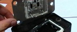
If during testing both secondary windings show integrity and serviceability, the reason for the inoperability of the coils may be a break in the soldering of the switch wires. Such damage is detected when the rear cover of the module is removed. If you have a soldering iron and know how to use it, you can restore the integrity of damaged contacts, while at the same time strengthening the rest. This, unfortunately, is the only failure of the ignition module that can be repaired.
Testing the ignition module can be done using simple do-it-yourself instruments. Based on our advice, you will be able to fully check both the module itself and other elements of the mechanism that may be the cause of the breakdown. We wish you success in this matter!
Read with this
Which is better?
SOATE devices manufactured in Stary Oskol have proven themselves to be the most reliable ignition modules.
Module structure
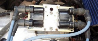
The module consists of two ignition coils and two high-voltage switch switches.
The coil generates a high voltage pulse, and it is a simple transformer with two windings, primary (induction voltage about 500 V) and secondary (induction voltage at least 20 kV). All this is assembled in a single housing, on which there is a connector for signal wires (from the engine control unit) and four terminals for high-voltage wires.
The module operates on the principle of an idle spark - it distributes sparks in pairs to cylinders 1-4 and 2-3 according to impulses transmitted from the ECU.
What are the advantages of VAZ 2107 injection models?
• The VAZ 2107 injection engine consumes less fuel. At the same time, it is more powerful than a carburetor engine with the same volume. This is achieved through the optimal formation of the qualitative and quantitative composition of the fuel mixture. Accordingly, the efficiency of an injection engine is higher than that of a carburetor.
• Thanks to electronic speed control, the engine runs more reliably at idle, stalls less when starting, and starts well at low ambient temperatures.
• Compared to a carburetor engine, an injection engine does not require frequent adjustments to the ignition and fuel supply systems.
• The air-fuel mixture that enters the cylinders has the most favorable composition. And the existing catalyst controls the minimum amount of harmful exhaust gases. This plays a big role in preserving the environment and taking care of health.
• There is no need to manually adjust the mechanism, since this is done by the hydraulic chain tensioner and hydraulic valve clearance compensators. They also guarantee less noise (noise insulation) when the engine is running.
• Torque graphics are “smooth”, a larger rpm range allows high torque to be achieved.
WORTH NOTICE! On an engine with an injection system, it is possible to install gas-cylinder equipment not only of the 2nd, but also of the 4th generation. This is a more modern and attractive option, since the installation of the 4th generation of gas equipment provides greater savings and reduces the occurrence of “pops” in the engine to zero.
Signs
- If one of the module coils completely fails, then two cylinders do not work. This is clearly visible even to the naked eye - the engine is feverish at idle, starting is difficult, fuel consumption is sky-high, loss of dynamics.
- To eliminate all other components of the ignition system, make sure that the spark plugs are in working order. To do this, unscrew them and check the spark on each of the spark plugs by cranking the engine with the starter and placing the spark plug with the high-voltage wire on the head so that the body (threaded part) of the spark plug touches the engine mass. If there is no spark or it is weak, replace the spark plug with one that is known to work.
- If this does not lead to anything, check the high-voltage wires. Thus, we will exclude spark plugs, caps and high-voltage wires from the list of non-working elements. Next we will check the ignition module.
Disadvantages of injection models of the VAZ 2107 engine
Of course, as usual, in addition to the advantages of the injection “seven”, there are also negative aspects, which consist in the following situations:
• Problematic access to some components due to the location of the engine and other mechanisms under the hood in the same format as in older models. Although at the same time, the system providing fuel injection is reliable and does not require frequent maintenance during operation.
Photo of VAZ 2107 under the hood
• The injection VAZ 2107 is equipped with a catalyst, which is very easy to damage when driving on a bad road with large bumps and obstacles. In such cases, of course, you need to be careful when driving on problematic roads.
Photo of VAZ 2107 catalyst
• The presence of an injection engine increases the requirements for fuel quality, in contrast to the carburetor version. If you use low-quality gasoline, you cannot avoid clogging the fuel system. This leads to unplanned vehicle maintenance.
• If the injection system breaks down, it is not possible to repair it yourself in a garage. Here you only need to contact professionals at a specialized service station.
How to check the ignition module?
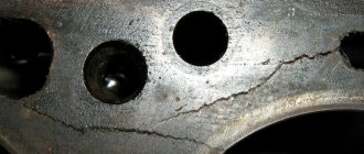
- First of all, we carefully inspect the module body. There should be no chips, burns or cracks on its surface. A module with a damaged casing is replaced without any hassle.
- If the spark is unstable only on cylinders 1-4 or 2-3, one of the module coils is probably damaged. In any case, we will conduct a comprehensive check of the device. For this we will need a regular multimeter.
Ignition adjustment in static position:
- Find a strobe light. If this is not the case, do the work by ear.
- Loosen the nut holding the ignition coil.
- Start the engine and warm it up.
- Rotate the distributor housing left and right.
- Command your assistant to watch the speed (they should be at 2000 rpm).
- Listen to the engine noise. Try to catch the moments when there are “dips” or changes in rotation speed.
- Achieve a situation where the engine runs smoothly and produces the highest speed. In this case, the work should be as rhythmic as possible.
- Tighten the distributor nut and operate the car.
Setting the ignition timing of the VAZ-2107 in motion:
- Warm up the engine to a temperature of 80-95 degrees Celsius.
- Accelerate to a speed of 40-45 km/h, then move the gearbox selector to the fourth speed position.
- Step on the gas and listen to the engine. If the ignition is set correctly, detonation appears, and after a while the engine speed increases. If you hear a clear knocking of the valves, turn the distributor as the clock hand rotates by about 1-1.5 degrees.
- Perform the manipulations described above until the extraneous sound disappears completely.
- If the speed decreases sharply after pressing the gas, turn the distributor to the same angle, but in the opposite direction.
Remember that adjusting the advance angle may not be enough - often the carburetor itself needs to be adjusted. To do this, find a couple of screws. With one of them you regulate quality, and with the other you regulate quantity. Also clean the carburetor from time to time.
As can be seen from the described technique, setting up electronic ignition on the “seven” is not difficult. At the same time, you can count on serious savings, because at the service station this service will cost a considerable amount.
Diagnostic procedure
The diagnostic procedure can be as follows:
- Disconnect the connector with signal wires from the module.
- Turn on the ignition and check the voltage at terminal 15 (central) of the control wire block. The rated voltage is 12 V. A drop or absence of voltage when the battery is charged indicates that the engine control unit does not supply power to the module. This means the reason lies in the ECU.
- We check the resistance of the primary windings of the coils - put the multimeter in resistance measurement mode and take readings from the rightmost and central terminals, then from the leftmost and central terminals. The nominal resistance of the primary windings is approximately 0.5 Ohm.
We measure the resistance of the secondary windings between terminals 1-4 and 2-3 high-voltage wires. Nominal value: 5.4 kOhm. If the readings do not correspond to the nominal value, the coil is not working correctly.
Check the module for a short circuit. To do this, install one tester probe on the central pin 15, the second on the metal body. The device should show the absence of a short circuit (one or infinity). Otherwise, one of the coils has shorted to the housing.
Classic, family 2101-2107
Domestic VAZ cars of the “classic family” (models 2101-2107) are equipped with carburetor and injection engines. Cars with carburetors have an ignition coil (or "bobbin") installed. The arrangement of the element is as follows: the part is mounted on the left mudguard in the engine compartment of the car, and is attached to the body using two nuts.
Cars with installed injectors (VAZ 2107) have an ignition module. It is mounted on the cylinder block of the car's power unit. The part functions together with the engine's electronic control unit, and the ignition coils are included in the design of the entire module.
The ignition module used is a universal model (installed on other domestic cars)
For the injector and as part of the BSZ, a coil 027.3705 is used, analogous to 27.3705 (ATE-2).
The characteristics of the “injection version” of the VAZ ignition coil are as follows:
Operating temperature from -40° C to +85° C Resistance value: primary winding (0.45+0.05) Ohm secondary winding (5+0.5) kOhm Supply voltage 12 V Overall dimensions 72x156 mm, oil-filled design
Errors
A module malfunction can also be determined using an error scanner. Error codes associated with the module are:
- R-3000, R-3001, R-3002, R-3003 and R-3004 - gaps in sparking, the module itself, spark plugs, high-voltage wires or the ECU may be to blame;
- R-0351 - the coil of cylinders 1-4 does not work;
- R-0352 - the coil of 2-3 cylinders does not work.
The scanner readings do not yet indicate problems with the module itself.
It is possible that the spark plugs are not working or the high-voltage wires are broken, but if we initially diagnosed them, then the fault lies entirely with the ignition module. In this case, we can repair it ourselves, or buy a new one, which is faster, easier and guarantees uninterrupted operation of the ignition system. Good luck to everyone, strong spark and good roads!
Design
The design of the ignition module is quite complex, since it combines technology and electrics. The device serves to create high voltage transmitted to the spark plugs. It is this supplied current that is the basis for ignition.
The operation of the module ensures fuel combustion and, accordingly, engine operation. In very simple terms, the car won’t go anywhere without the module.
For VAZ models, the use of two types of ignition modules is provided:
- Separate;
- Block.
Block ones differ in that the coils operate one per pair of spark plugs. These are the devices that are installed on the “fourteenth” model of the domestic automaker.
The coil distributes power to two candles at once, and its design includes the following elements:
- High voltage wires;
- Low voltage terminals;
- Secondary and primary winding;
- Core.
Separate modules, where the coils supply a separate circuit to each of the 4 sections, are distinguished by the output of high-voltage wires through a spring contact. Block ones are easier to check, they are easy to remove and return to their place.
It is noteworthy that with a size of 11x11x7 centimeters, this block weighs about 1.5 kilograms.