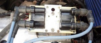
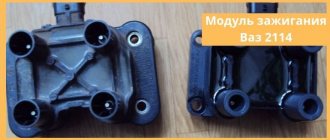
Ignition module
As mentioned above, the “ten” has 4 engine types: 16 and 8 valve internal combustion engines, as well as with a volume of 1.5 and 1.6 liters. This will lead to differences in the ignition modules. Depending on the installed engine with a certain volume, its own ignition module will be installed.
Differences
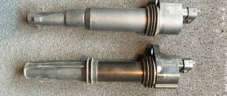
The main differences between the modules will be the size and mounting holes. In a 1.5 liter internal combustion engine, the ignition module is larger in size in contrast to the 1.6 liter engine. The cost of the modules depends on the manufacturers, but it should be noted that the MZ from a 1.5 liter engine is always more expensive than a 1.6 liter one.
16 valve MZ
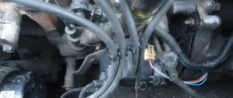
In a 16-valve internal combustion engine, the ignition module is installed on the valve cover near the oil filler neck.
8 valve MZ
The MZ on an 8-valve engine is installed on the front of the cylinder block between the dipstick and the breather.
Device
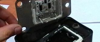
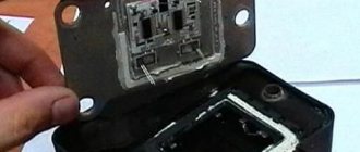
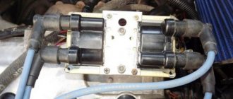
The ignition module has a common structure regardless of engine size. Inside the switch there are two high-voltage coils and an electronic circuit with many keys.
The coils are designed to switch high voltage and supply it to the spark plug to form a reliable spark in the combustion chamber of the engine.
The ignition module produces a spark in pairs, that is, each of the coils located inside the module is responsible for generating a spark on two cylinders: the first-fourth, the second-third.
Finding the origin of the problem
First you need to check the performance of the spark plugs, and this check may indirectly indicate a coil malfunction.
To check, you just need to unscrew the spark plugs, insert them into the tips of the high voltage wires, massage them and turn the crankshaft several times with the starter. In this case, you should look at the spark that forms between the electrodes.
If it is discovered that a spark plug is not working correctly and the spark in it is formed intermittently, it should be replaced and a known good one installed in its place.
If a working spark plug works intermittently, check the high voltage wire.
If the interruptions persist even when the wire is replaced, then in carburetor cars the distributor is inspected next, and only then the coil.
In injection cars equipped with a module, there is no such distributor, so you can immediately start checking the module.
Checking these elements will not be particularly difficult, and the only equipment you will need is a multimeter with the ability to operate in ohmmeter mode, with a measurement range of up to 200 MOhm.
To make it more clear, let’s look at how these ignition elements are checked on different cars.
Symptoms of a problem
Based on some signs, it can be determined that the culprit of a malfunctioning internal combustion engine is the MZ. Below is a small list of symptoms indicating failure of the MH.
- Failure of two cylinders at once, namely 1-4 or 2-3;
- Increased fuel consumption;
- Detonation at idle speed;
- The engine does not develop power;
- Difficult starting on a hot internal combustion engine;
These signs indicate a malfunction in the ignition system. These signs also apply to other possible breakdowns: spark plugs, wires and even injectors, but first of all you need to pay attention to the MH.
Diagnostics of the secondary winding
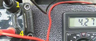
In the secondary winding, the resistance is no longer measured between three, as in the primary winding, but between four contacts: 1, 2, 3 and 4. As is clear, each of the contacts corresponds to the serial number of the cylinder. The Daewoo Lanos coil is visually divided into 2 parts, right and left. One half is reserved for contacts to the first and fourth cylinders. In the second half there are contacts to the second and third cylinders.
The secondary winding is considered fully operational if the resistance between the contact pairs is from 4.8 to 5.6 (kOhm). When monitoring resistance in the secondary winding, the resistance value of the probes is usually neglected.
When the resistance of the first contact pair was 5 (kOhm), and in the second 5.5 (kOhm), then in this case there is a clear imbalance. Yes, such a coil is also useful, since its resistance fits within the tolerance range. But due to the large difference in resistance between the contact pairs, such a coil can be considered partially broken .
Source
Module check
After signs similar to failure of the ignition module appear, it must be checked before buying a new one, since its cost is not cheap.
There are three ways to check: substitution, visual inspection and a multimeter.
Substitution
The best and easiest way to check the MZ is to install another known good one from another exactly the same car. After which it will immediately become clear what the matter is and whether the Ministry of Health is to blame for this problem.
Visual inspection
It is necessary to inspect the module for chips, cracks, etc. There should be no damage to it. There should be no moisture or rust on the contact part.
Multimeter
Testing with a multimeter is carried out using the results of voltage and resistance measurements. This will help identify the cause of the failure of the module or its control circuit.
Step by step check
- Remove the power supply from the module. On the multimeter we set the DC voltage measurement limit to 20V. We turn on the ignition on the car and connect the multimeter contact on one side to the power block (namely to connector 15), and on the other side to the engine housing. The voltage between pin 15 and the motor housing must be at least 11-12V. Otherwise, the power supply circuit of the MH is faulty, or the battery is discharged.
- Next, we check the resistance on the VAZ 2110 ignition module itself. We set the multimeter to the resistance measurement parameter, namely 200 Ohms. We connect the multimeter probes to the high-voltage terminals of the MZ: 1-4, 2-3. The resistance of these coils, with a working MC, should be within 5 ohms.
- Then the resistance at the MC input is checked. One multimeter probe is connected to the central contact and the resistance is measured first on the leftmost contact and then on the rightmost one. The resistance should be in the 5 ohm range.
How to check input wires for serviceability
Following the recommendations of specialists, to check the condition of the wires at the input, they need to be “ringed”. What does it mean?
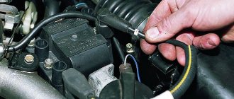
- Determine the operating format of the multitester in the voltmeter position, and then disconnect the wiring block from the VAZ-2114 ignition module.
- Focusing on contact A, mount the first dipstick, and fix the second one to the engine ground.
- Ask an assistant to start the car or, alternatively, crank the starter. At this time, your task is to observe the measurements on the display. Normal voltage is 12 volts.
- Carry out exactly the same actions with the remaining contact.
What to do if there is practically no voltage? Then evaluate the serviceability of the fuse - it is likely that it has blown. Find 3 safety mechanisms on the VAZ-2114 electronic control panel. So, the third 7.5 A is a device suitable for the car module.
Even if the fuse is intact and intact, there is a possibility of oxidation and wire breakage, as well as loose contacts.
What to do if there is no multitester available? A control light designed for 12 V will help solve the problem. One wiring of the lighting device is placed to the contact of the block, and the other is closed to the motor housing. After turning on the ignition, the light should flicker.
How to check the VAZ-2114 ignition module with your own hands is shown in the video instructions:
Cost and article
The table below shows the cost of the VAZ 2110 ignition module depending on the manufacturer and VAZ engine size.
| Engine volume | Number of valves | Manufacturer | vendor code | Price, (rubles) |
| 1,6 | 8 | JSC SOATE | 2111-3705010-03 | 905 |
| 1,5 | 8 | BOSCH | F000ZS0211 | 2600 |
| 1,5 | 16 | StarVolt | 2112-3705010 | 1600 |
| 1,5 | 16 | Omega | 2112-3705010 | 1590 |
We check the ignition module on the injection VAZ-2110 8 valves with our own hands
At different times, different engines were installed on the VAZ-2110 car, both carburetor and injection. However, regardless of the type of power system and the number of valves (8 or 16), all engines are assembled on the unit base of the old engine 21083 and 21093. The most progressive of these engines is the 16-valve 1.6-liter VAZ 21124 engine with a power of 89 horsepower. Today we will touch on the ignition module for 8-valve engines 2111 and 21114 (1.6 l), check its performance and find a suitable replacement for the failed module.
Version of the module on the 8-valve VAZ-2110
The top ten was equipped with two 8-valve engines of different sizes - 1.5 (2111) and 1.6 liters (21114). The ignition modules for these engines are different.
- The one and a half liter engine has a module with article number 2112-3705010,
- and the 1600 cc is equipped with module 2111-3705010.
A module for a 1.5 liter engine costs about 1500-2100, and the second one is 500 rubles cheaper.
Which is better?
SOATE devices manufactured in Stary Oskol have proven themselves to be the most reliable ignition modules.
Module structure
The module consists of two ignition coils and two high-voltage switch switches.
Inside the module there is a board with radio components and ignition coils filled with compound.
The coil generates a high voltage pulse, and it is a simple transformer with two windings, primary (induction voltage about 500 V) and secondary (induction voltage at least 20 kV). All this is assembled in a single housing, on which there is a connector for signal wires (from the engine control unit) and four terminals for high-voltage wires.
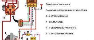
Schematic diagram of the module.
The module operates on the principle of an idle spark - it distributes sparks in pairs to cylinders 1-4 and 2-3 according to impulses transmitted from the ECU.
Is the renovation still relevant?
When the symptoms have been identified and the ignition module has been diagnosed, it’s time to decide: try to “save” the old device, or replace it with a new one. The choice is not an easy one, especially considering the fact that repair of the ignition module is possible only on contact connections; in rare cases, it is possible to replace the coil or transistor. For a complete repair we will need:
- Screwdriver;
- Hexagon 5;
- Soldering iron;
- Multicore cable;
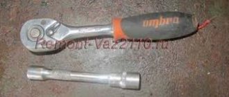
- Socket wrenches for 13 and 17;
- Nail polish;
- Flux for aluminum.
We repair the ignition module in the following order:
- We dismantle the device;
- Use a screwdriver to open the case;
- Carefully get rid of the silicone film, which probably covered the entire board;
- All aluminum in the area of explosive contacts is cleaned.
- We remove absolutely all the wires from the board and solder new ones. To do this, clean the surface of the board from plaque and heat it to a temperature of 180 degrees.
- After finishing the work, all contacts, the board and the module itself are varnished.
- The device is mounted in its original seat, and if the final diagnostic results are positive, the ignition module is firmly seated on the sealant.
If you were unable to restore your device, don’t be upset; not everyone can do this task! But now you know exactly how the ignition system works and what it actually is. Moreover, you can easily tell us how to ring the chain, and if necessary, you will take on the repairs yourself. Well, isn't this enough? Looking forward to the next post, but I’m done here! See you later!
