Yesterday, in the comments to one of my articles, I came across a question about the ignition coil or ignition module. I’m used to calling it an ignition coil, so we’ll stop there. Moreover, in fact, these are coils. In general, let's start figuring out where the ignition coil is, how to remove it, how to put it on, how to check it with a multimeter, and so on. Fasten your seat belts and let's go.
Signs of a bad ignition coil!
What does the ignition module consist of?
This is a separate car system that functions normally only if all its elements are in good working order. The main components that it includes:
- Electronic engine control unit (supplies constant voltage to the winding).
- Two ignition coils and two switches, which are located in a solid plastic case. Thanks to induction, the device generates high voltage. The first coil is responsible for cylinders 1 and 4, the second – for 2 and 3.
- The current is transmitted through high-voltage wires to the spark plugs. The system also has terminals for connecting the on-board network.
It must be remembered that malfunctions can also be caused by faulty sensors, so they should also be checked if problems arise. To reduce the likelihood of breakdowns, you need to change consumables on time - spark plugs and high-voltage wires, and also inspect all contacts at least once a year.
Basic Verification Approach
Since the windings play a key role in the operation of ignition coils, the first thing that needs to be checked, regardless of the type of device, is their resistance.
Thus, the resistance indicators of the primary winding can vary according to different data:
- from 0.6 to 4 Ohm;
- from 0.5 to 3.5 Ohm.
Secondary:
- from 6 to 15 kOhm;
- from 3 to 11 kOhm.
The indications are different because they can be different for each car model, so it is important to study the documentation for the car and the technical characteristics of the coil itself.
It is also important to understand that for each type of coil, indicators such as the inductance of the primary winding, the resistance of both windings, energy, duration and spark current may differ.
Measurements are performed with a multimeter or a regular ohmmeter.
If there is a strong deviation from the standard data, the ignition coil is most likely damaged. But there is no need to rush to change it; there are other ways to check.
Frequent malfunctions on the VAZ 2114 and other models
There are several main signs by which you can determine that the ignition system is not working properly. The most common problems:
- Two cylinders stopped working. Since each coil is responsible for a pair of elements, if it fails, they do not function. The engine stalls, operates with great interruptions, traction is greatly deteriorated, and fuel consumption increases significantly.
- Starting the engine becomes more difficult; you need to turn the starter several times before the car catches on. This is due to a violation of the spark supply to the spark plugs or its absence.
- Power dips may occur from time to time. For example, during sudden acceleration, prolonged movement uphill or under high loads. Sometimes this is observed when driving in a straight line, which manifests itself in the car jerking or spontaneously slowing down.
- The idle speed fluctuates or jumps for no apparent reason. If you listen to the car from behind, the work will be uneven, with interruptions and changes in the speed of rotation of the crankshaft.
Failures can be either permanent or temporary, especially if the problem is with spent spark plugs or high-voltage wires. In some cases, the car simply stops starting.
For your information! In the event of a malfunction, a check will light up on the panel if it is working properly. Many people ignore it, which makes the problems worse. Therefore, it is worth checking the car yourself or taking it for diagnostics as soon as possible after the malfunction signal appears.
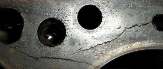
What is ignition coil breakdown and its causes?
Let's take a brief look at what coil breakdown is, what it affects, and what it looks like visually. First of all, it should be recalled that the coil itself is a transformer that has two windings (primary and secondary), isolated from each other. The definition of breakdown is a physical phenomenon when, due to damage to the primary and/or secondary windings of the coil, part of the electrical energy falls not on the spark plug, but on the housing. This leads to the fact that the spark plug does not work at full power, and accordingly, the engine begins to “trouble” and its dynamics are lost.
Ignition coil device
There can be many reasons for the breakdown of the ignition coil - damage to the insulation of one or both windings, damage to the tip body, damage to its rubber seal (due to which water gets inside, through which electricity “sews”), the presence of dirt on the body (similar to water, current passes through it), damage (oxidation) of the electrode in the tip. However, most often the problem lies in the “wired” insulator, and therefore, to eliminate the problem, this place must be localized and insulated.
An interesting reason for the failure of ignition coil tips is the fact that when replacing a spark plug, in some cases, car owners, through carelessness or inexperience, can tear their waterproofing. This can lead to moisture getting under them and problems with engine operation. The opposite case is that when the car owner tightens the top nuts of the spark plug cups too tightly, there is a risk that engine oil from the engine will begin to penetrate into the plug housing. And this oil is harmful to the rubber from which the reel tips are made.
Also, the reason that spark breakdown occurs outside the cylinder is incorrectly set gaps on the spark plugs. This is especially true if the gap is increased. Naturally, the spark in this case has a detrimental effect on both the spark plug body and the rubber tip of the ignition coil.
Signs of coil malfunction
Before starting an instrument test, you can try to determine whether the ignition coil of the VAZ 2114 8-valve injector is working by indirect signs (in some cases they are enough to verify a breakdown).
- instability (intermittency) of idle speed;
- the engine gains speed with great difficulty;
- “triple” when the engine is running;
- The speed gain while driving occurs in strong jerks.
If these signs are present (especially if there are several of them), you can either immediately replace the faulty module, or finally establish the fact of its malfunction using instrumental analysis.
Signs of breakdown
The reel has a reliable design and its service life is significant. And yet this element can also fail.
The main signs that the ignition coil is not working properly are:
- Inability to start the power plant;
- The inscription “Check Engine” appears on the dashboard (on cars with an ECU), and when scanning the system, code P0363 is displayed, indicating a malfunction of the ignition module (on modern injection cars);
- Decrease in power unit performance;
- Misfires, which causes the engine to “trouble” (with time the problem becomes more pronounced);
- Dips when reaching certain crankshaft speeds.
It should be noted that these malfunctions are also typical for other elements of the ignition system, for example spark plugs, so before you “sin” the coil, you should check the entire circuit coming from it.
How to determine faults at service stations
The easiest way is to entrust the troubleshooting to professionals who have all the necessary equipment. Ideally, a car service center should have certified diagnostic equipment, and not universal ones purchased on the Internet. Licensed software is much better at identifying all problems, minimizing the likelihood of inaccuracies. Ideally, find a certified VAZ service center.
As for diagnostics, everything is quite simple:
- The adapter is connected to a special connector, after which all indicators are checked with the car running. The process takes just minutes, so there is no need to leave the car for a long time.
- After scanning, error codes are issued, by which it is not difficult to determine malfunctions. All codes are in the reference documentation.
- Next, all problematic components are replaced or repaired. After this, be sure to check again to make sure there are no errors.
If you have a suitable adapter and computer software, you can diagnose problems yourself. It’s not difficult to figure it out; usually the equipment comes with detailed instructions, and there are also many training videos on the Internet.
Car modifications 2115
VAZ-2115 . The very first car that was produced since 1997. It was equipped with a 1.5-liter carburetor engine producing 76 horsepower. The maximum speed was 165 km/h, and the acceleration time from 0 to 100 km/h was 13.2 seconds.
VAZ-21150 . The next modification, released in 1998, was equipped with a 1.5-liter carburetor engine producing 68 horsepower. was discontinued in 2000.
VAZ-2115-20 . A modification of the car released in 2000, equipped with a 1.5-liter VAZ-2111 injection engine with a power of 77.8 horsepower. The maximum speed was 170 km/h, and the acceleration time from 0 to 100 km/h was 14 seconds.
VAZ-2115-40 . A modification with a 1.6-liter injection engine, which has been produced since 2003. The car's maximum speed was 158 km/h, and the acceleration time to 100 km/h took 13.2 seconds.
VAZ-2115-91 . A car with a 1.3-liter Wankel rotary piston engine producing 135 horsepower. The maximum speed is 190 km/h, and the acceleration time to 100 km/h is 9 seconds.
VAZ-21154 . The latest modification of the car with a new VAZ-11183 engine with a volume of 1596 cm3 and a power of 81 horsepower. Produced since 2007. The maximum speed and acceleration time to 100 km/h are exactly the same as that of the VAZ-2115-40.
Checking the ignition module with a multitester
You can buy a multimeter at any auto store. It is inexpensive and useful for checking all electrical elements of the car. Even if you have no experience in such work, you can follow simple instructions and easily carry out diagnostics in the garage or right in the yard:
- To check the ignition module itself, you need to check the contacts going to the high-voltage wires. To do this, you need to set the device to ohmmeter mode and measure the readings. First do this on cylinders 1 and 4, and then on cylinders 2 and 3. If everything is in order, the resistance readings at each of the terminals will be in the range from 5.2 to 5.5 kOhm. If the difference exceeds 100 ohms, we can confidently say that the problem lies in the secondary winding.
- You should also check the contacts without using any devices. To do this, the engine starts, then you need to open the hood and slightly pull the body in different directions. When there are no changes in operation, everything is in order: if interruptions occur, you need to check the connections. If this does not help, most likely the reason is in the module itself. It cannot be repaired; the easiest way is to replace it.
What should I do if the problem remains after replacing the module?
If, after performing the repair, problems in the operation of the MH remain, then there is a possibility that the cause of the problem was not in the module. It is necessary to diagnose the remaining elements of the ignition system.
Spark plugs and ignition system
Features of checking spark plugs and other components:
- Before dismantling the devices, it is necessary to disconnect the ends of the high-voltage cables. Their condition is checked for damage. Defects in the tips often lead to malfunctions in the spark plugs. If there is damage, the wires are replaced. It is also necessary to assess the condition of the “high-voltage workers” themselves. They are not allowed to have any defects or damage to the insulation.
- After disconnecting the tips, the spark plugs are dismantled and a special spark plug wrench is used to unscrew them.
- After dismantling, the condition of the devices is assessed. The color of the parts must be brown; carbon deposits and soot on the electrodes are not allowed. If there are uncharacteristic marks, the devices are cleaned using a metal brush or fine-grained sandpaper. For a better effect, the electrodes of the candles can be heated on the stove.
- The condition of the gap between the part and the electrode element is checked. If it is too large, this indicates that the device is not working correctly. The spark plugs will need to be replaced.
Video “Visual instructions for replacing the module with your own hands”
How to replace the ignition module on a car at home - see the visual instructions in the video below (the author of the video is the PROauto161 channel).
At different times, different engines were installed on the VAZ-2110 car, both carburetor and injection. However, regardless of the type of power system and the number of valves (8 or 16), all engines are assembled on the unit base of the old engine 21083 and 21093. The most progressive of these engines is the 16-valve 1.6-liter VAZ 21124 engine with a power of 89 horsepower. Today we will touch on the ignition module for 8-valve engines 2111 and 21114 (1.6 l), check its performance and find a suitable replacement for the failed module.
Literature on passenger cars VAZ 2114, 2113, 2115 and their modifications
Here you can download the necessary books required for the operation of passenger cars of the VAZ 2114, 2113, 2115 family and their modifications.
| 1 | Reanimation of a car in road conditions VAZ 2113, 2114, 2115. | 2007 | 49 pp. | Size - 1.71 MB | Format - djvu |
| 2 | OPERATING MANUAL FOR VAZ-2113, -2114, -2115 CARS AND THEIR MODIFICATIONS | 2002 | 88 pp. | Size - 751 KB | Format - pdf |
| 3 | Distributed fuel injection systems for VAZ cars - design and diagnostics | 2003 | 128 pp. | Size - 1.67 MB | Format - pdf |
How to check input wires for serviceability
Often problems arise due to a lack of power to the module. To test the wiring, you need to use a multimeter, which must be set to the voltmeter position before starting work. No preliminary preparation is required in this case. It is better to park the car in a well-lit place, open and secure the hood. Follow simple instructions:
- The car must be turned off and the ignition turned off. First of all, disconnect the wire block by pressing the fastener with a screwdriver or other suitable object. It tightens with moderate effort.
- One probe of the device must be pressed to the contact marked “A”, the second should be applied to ground (any exposed metal on the car body). The main thing is that the contact is good, otherwise it will not be possible to take readings.
- Next, you need to ask an assistant to start the starter for a few seconds; the car will not start with the block removed, but the indicators can be taken. When the starter rotates, the voltage should be 12 V, there may be deviations, but small.
- Check other contacts in the same way, alternately changing the position of the probe from the voltmeter. The mass may be in one place.
If there is no voltage or it is much less than normal, you need to check several basic elements. The work is not difficult and takes literally a few minutes, since malfunctions are usually typical and occur in the same places:
- Replace the fuse. You can find it according to the diagram under the compartment cover or according to the instructions for the car. An element with a rating of 7.5 A is responsible for the ignition module; you need to install the same one. Even if the appearance of the fuse is normal, it is better to change it, since the contacts may be oxidized or the damage may be subtle, but significantly affect the operation.
- Check all wiring connections: vibrations can cause contacts to loosen or move away, and they often oxidize due to moisture. In the first case, you need to put the chips on more tightly or tighten the nuts, in the second, remove the limit switches and clean them of oxides, then apply a special compound for the contacts and put everything in place.
- If everything is in order there, then most likely the culprit is damage or a broken wire. You need to test each core in order to find the problem area. When troubleshooting a problem on the road, you can twist it and wrap it with electrical tape, but it is better to change the wires so that they are solid from start to finish.
VAZ 2115 diagram
Detailed color wiring diagrams for the VAZ 2115 (carburetor, injector) are provided with a description of the electrical equipment for various modifications. The information is intended for self-repair of cars. Many electrical circuits are divided into several sections for ease of viewing via a computer or smartphone; there are also circuits in the form of one picture with a description of the elements - for printing on a printer.
If you need to distribute power to external consumers (DVR, headlight washer, radio) when you turn on the ignition, it is better to take power from the battery through a relay. According to the scheme, 86 for the body, 85 for the ignition (for example, yellow-blue heater switch). Contact 30 through a 30 Amp fuse to the battery, 87 to consumers. That is, when you turn on the ignition, the new relay will turn on and the power will come directly from the battery.
WE MAKE THE REPLACEMENT WITH OUR OWN HANDS
Ignition of the fourteenth is a dubious task, since once a device fails, it will continue to “delight” you in the future, so it is much easier to install a new, normally functioning unit. Moreover, it is impossible to do a complete repair of the unit with your own hands - you will need to go to a service station.
Removing the ignition module is performed as follows:
- Remove the “-” terminal from the battery;
- Unscrew the tips of the spark plugs;
- Disconnect the block from the LV module power wires;
- We remove the high-voltage wires - you just need to remove them from the special connectors;
- Unscrew the bolts that secure the bracket holding the unit on the crankcase of the fourteenth engine;
- We dismantle the assembly together with the bracket;
- Disconnect the device from the bracket.
To do everything yourself you will need 13 and 17 keys, a screwdriver and a set of hex keys. Knowing how to ignition, it will take 1-2 hours to identify faults and, if necessary, replace the unit.
Source
For what malfunctions is it possible to repair the device?
Due to the fact that the ignition module by design includes a connection of two coils, it is difficult to repair. If there is a break or breakdown, as well as melting of the turns, the problem can be solved by replacing the device. This applies to any damage that appears inside the coils. The only option to correct the situation without replacing the device is to repair the damage to the solder joint.
Ignition module repair process
The repair procedure is carried out after preparing all tools and materials:
- a set of socket wrenches, you will need a tool for 10, 13 and 17;
- hexagon 5;
- flat head screwdriver;
- soldering iron with aluminum and flux;
- nail polish;
- multi-core conductors.
Restoring the ignition module operation is done as follows:
- The key is installed in the switch. The engine starts. Then you need to move the contact elements on the module to make sure they are not working.
- The power unit stops. The module is being removed.
- The device body is cleaned from dust. To disassemble, you need to open the case; this is done by prying it off with a screwdriver. Inside the device there is a board on which there is a silicone film; you need to get rid of it.
- Aluminum is removed from high-voltage contact elements. Old wires are removed.
- The next step will be soldering new conductors to the circuit. To do this, the surface of the collector device is cleaned from traces of plaque. Then the board must be installed on an electric stove and heated to approximately 200 degrees. As the temperature increases, a slight burning smell may be heard. This is not a problem for the circuit; heating it will simplify the soldering procedure.
- Then soldering is done. Using a soldering iron, flux and aluminum, the ends of the conductors must be connected to the ignition module. All contact elements of the conductors that are connected to the circuit must be treated with nail polish.
- Then the device is assembled in the reverse order and installed in the seat. After installation, the power unit starts up. If the repair solves the problem, then using a sealant, the device is fixed in place.
- If a transistor or switching device fails, then these components cannot be repaired, but they can be replaced. To do this, the parts are removed from the board and replaced with new ones.
How to check the ignition module of a VAZ 2115 injector
Ignition module. I’ll say right away: there are no simple tests that can reliably evaluate this element of the ignition system. For the reason that the spark formation process itself cannot be called simple. First, the accumulation of inductive energy in the coil, then saturation, breakdown of the spark gap, the occurrence of an arc, its combustion, and finally, damped oscillations. Each stage has its own characteristics, characteristics and parameters, everything has its essence and weight. Changes in characteristic quantities: accumulation time, breakdown voltage, combustion voltage, arc burning time and distortion of the shape of damped oscillations provide a lot of information about the health of the coil or module. All this is clearly visible on the monitor of a motor tester or oscilloscope, and deviations in individual cylinders are clearly visible in comparison. But according to the terms of this topic, we, like most car enthusiasts, have nothing except a control unit and a Chinese tester. Well, no need, we’ll try to get out of it, there are no hopeless situations.
Actually, there are only 2 methods worth attention left: Determination of performance by the arrester and the simple replacement method. The first method is often used, but it involves having a spark gap itself, and is based on the fact that a working ignition module should be able to spark a 20mm air gap with any of its terminals. A defective module channel will not be able to do this. Personally, I like the arrester design with an adjustable or 4-step gap of 5, 10, 15, 20 mm. By running the coil leads one by one, you can see when the weakest one gives up. I will not dwell on this in detail, the designs of arresters and descriptions of the method in the sea network. The method works, although it has certain limitations and requires some experience and skill. Therefore, I would like to focus on the second method - simple substitution, especially since it is the most accessible for car enthusiasts.
This is a really simple method, but there is one point. The ignition module is designed in such a way that it easily develops a voltage of 20 kilovolts at its terminals. When a control pulse is received from the control unit, a high-voltage discharge through explosive wires rushes to ignite the mixture compressed in the cylinder. Question. Where will the charge go if the wire is suddenly broken? (or will be completely absent - for the module this is the same thing) The discharge is looking for a way out, and unfortunately, it quickly finds it. Most often, the module pierces its own insulation with its own energy and begins to “sew” to ground along the shortest current path. Where the insulation is weakest. The trodden path drains the charge energy onto the ground, as a result, 2 cylinders fail at once. Either 1-4 or 2-3, depending on which wire breakage triggered the insulation breakdown. The insulation may turn out to be good, then a breakdown is possible between the turns of the coil itself, again inside the module. Moreover, a breakdown can cause an interturn short circuit, or it can simply be sewn when the breakdown conditions, even on a serviceable wire, are the most severe.
And these are moments of maximum load on the engine, for example, intense acceleration. Another question is which turns will close: if they are extreme, then the channel will fail. And if they are adjacent, then the coil will lose power, and almost imperceptibly to the eye - the inductance is no longer the same. But this is for the time being. Soon, twitching, adjustments, jerks and dips, idle speed fluctuations, and other troubles will begin. These are not all types of module malfunctions, but the couple listed above indicate that its health largely depends on its operating conditions. Therefore, in relation to our method, the question is: What will happen if, without checking the serviceability of the explosive wires, you install a known-good ignition module on your car as a replacement, kindly provided by a neighbor? (if one of the wires is broken, and the module is probably fried for this reason) Nothing may happen: your neighbor’s module may turn out to be more powerful than yours, and for the duration of a short test it will cope with the task, breaking through the gap, and you, making a mistake in diagnosis, buy a new one , which will not live long due to a broken wire.
Principle of operation
The operation of the ignition coil is based on the principle of operation of a step-up transformer, when a small voltage of 12 V is converted into several thousand volts.
Voltage conversion occurs thanks to two windings - primary and secondary, which were mentioned above. In the first, a decreased U is created, in the second, an increased one.
Depending on the type of device, the location of the windings and their design differ.
Principle of operation:
- The breaker closes the electrical circuit and voltage is supplied to the primary winding. Due to this, a magnetic field is generated in the coil.
- After opening the circuit, the magnetic field disappears, but passing through the secondary winding it generates a high voltage in it.
The operating principle of the ignition coil is clearly presented in the video.
Coil types:
- Regular.
- Individual.
- Two-terminal.
Regular ignition coil
Here the primary winding is a metal core (to increase the magnetic field) around which 150 turns of thin insulated copper wire are wound, the ends of which are brought out to the housing.
The secondary high voltage winding is a thin insulated copper wire wound around a metal core with up to 50,000 turns.
The second winding is connected to the first by negative wires. The positive wire of the high voltage winding is brought out to the cover and connected to a special terminal.
Some models of ignition coils contain transformer oil as an insulator and for cooling purposes.
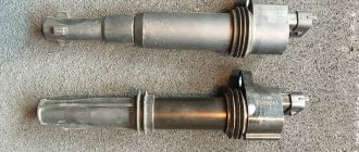
Custom ignition coil
Their design is more complex than conventional coils; they are installed on engines with electronic injection.
Structurally, they also have two windings, which differ from each other not only in the number of turns and wire thickness, but also in the reverse order of winding.
So in the primary winding the core is located as usual inside, and in the secondary winding outside. Also in the secondary winding, in order to cut off very high voltage, a diode is provided.
Also, thanks to special design solutions, it became possible to supply high U not to the distributor, as is the case with a conventional coil, but directly to the spark plugs.
Two-pin
Such an ignition coil immediately supplies voltage to the spark plugs of two cylinders, i.e. on a four-cylinder engine there will be two of them and they will be combined into one block, which is essentially a four-terminal coil.
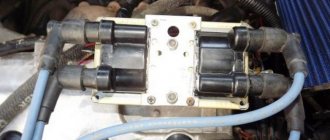
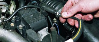
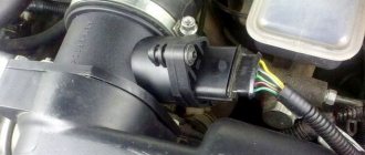
Where is the ignition coil located?
Let's look at the example of a VAZ car; you can find the ignition coil quite simply by tracing where the high-voltage wires from the spark plugs go.
From the photo above you can see the area where the ignition coil is installed, but look in more detail at the next photo.
To remove the ignition coil, you need to unscrew three nuts, two of them are clearly visible in the photo above.
Well, basically, that’s all there is to say about dismantling, there’s nothing more to say, unscrew the 3 nuts, disconnect the wire and that’s it, the ignition coil is removed. Let's move on to the next point: coil diagnostics.
Explanation of the ignition coil designation (Catalogue number) - 2111-3705010;
The designation of a part or assembly is a unique number in a single form. Assigned to only one part. The numbering of designations for assembly units and parts is carried out according to a unified seven-digit system. Designation - 2111-3705010-02 is deciphered as follows. The first four digits before the dash indicate the model of the base car or engine, chassis, body. In our case: 2111 is the engine model. The first two digits after the dash indicate the group number, in this case 37 - electrical equipment. The next two digits are the subgroup number. In our case, 05 is the ignition coil. The last three digits of the seven-digit number indicate the serial number of the part. The last two digits after the second dash indicate the interchangeability of the part. ХХХХ-ХХХХХХ-00 (to-09) - interchangeable. ХХХХ-ХХХХХХХ-10 (up to 19) are interchangeable with each other but not interchangeable with ХХХХ-ХХХХХХХ-00 (up to-09) and so on.
The part designation is applied to the body of the part. It helps determine the interchangeability and suitability of a particular part when purchasing and searching for it.
How to check the ignition coil of a VAZ with a multimeter, checking the circuit?
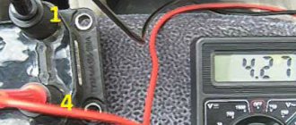
The first thing you need to decide is whether the coil is not working or something in front of it. To do this, take the terminal from the ignition coil in one hand and a milliliter in the other hand and begin testing. Although, before I continue my story, you probably need to familiarize yourself with the pinout of the wires. Therefore, look carefully at the following picture.
Now I’ll explain the picture, we have 4 wires, 2 signal wires, one ground and one power. You need to check all 4 wires, let's start in order; by the way, the pinouts A, B, C, D are not marked on the plug itself. Let's start checking with the power cable. Turn on the ignition, connect one multimeter probe to the negative terminal of the battery, and the other to terminal D. The voltage should be 12 volts.
My test shows 11.86 volts, now we know that voltage is coming to the coil. Next, let's check the ground; this is pin number C; for this, we connect the multimeter probe to pin C and the other to the positive terminal of the battery.
There is also contact with the ground. We can check both wires at once by connecting a milliliter to pins C and D, the voltage should also be 12 volts. Let's move on to checking the signal wires. A and B To do this, switch the multimeter to resistance measurement mode.
I stuck the wires in from different sides because it was impossible to hold everything in place with one hand. My multimeter showed 1.17 kOhm, sources on the Internet say that the resistance should be below 1 kOhm, most likely something, somewhere, has oxidized, by and large, it wouldn’t be bad to start figuring it out, maybe there are problems in the ECU, but today we’re dealing with ignition coil.
Total: we found out that the voltage to the ignition coil comes with the signal wires, and everything is in order. So we move on to the ignition coil itself.
Causes of malfunctions
Ignition coils are reliable devices and the main reasons for their failure include: insulation breakdown, limiting service life.
Below we list other reasons why a device may fail.
| 1. Aging and mechanical damage. | During operation, the materials from which the ignition coil is made lose their strength, begin to crack and collapse, and various liquids (oil, antifreeze, etc.) can affect the device, which negatively affects its service life. There is only one solution - replacement. |
| 2. Damage or oxidation of the contact connection. | Penetration of moisture under the hood, a humid climate, after fording, improper washing of the engine or car, all this can affect the condition of the contacts and their rapid oxidation. |
| 3. Vibrations. | Individual ignition coils of electronic injection vehicles are very sensitive to vibrations. For example, if the motor is tripping, or one of its supports is out of order, it vibrates strongly. Also, very bad roads, which are not uncommon here, can cause severe shaking and affect the position of the reels. |
| 4. Overheating. | The same applies to individual coils, which are located near the cylinder head, where the temperature is highest. In the intended temperature conditions of the engine operation, nothing will happen, but if, as a result of poor quality coolant or for other reasons, the engine overheats, this will negatively affect the ignition coil as a whole. |
How to check the ignition coil of a VAZ with a multimeter?
To make checking easier, the coil needs to be removed, but you can do this all on the engine. You need to switch the multimeter to resistance measurement mode and take measurements on the coil contacts. We measure the resistance at terminals 1-4 and 2-3; note that there are numbers on the ignition coil; they correspond to the cylinder numbers.
The resistance should be around 5.5 kOhm. In my case, the resistance is 5.9 kOhm, which in principle fits into the standards; we take further measurements.
Source
MH errors
The following errors are associated with the malfunction of the MH:
- P0351 - coil breakage of cylinders 1-4.
- P0352 - cylinder 2-3 coil breakage.
- P3000 (P3001 P3002 P3003 P3004) - multiple misfires.
The faulty module must be replaced (MZ replacement) or repaired (Ignition module repair).
A common cause of this error can be both spark plugs and high-voltage wires - they need to be replaced (How to replace high-voltage wires? How to replace spark plugs?).
VAZ-2115 wiring harness diagrams
With a 9-pin square block for the injector, a non-locking button for turning on the automatic transmission, and a starter blocking relay (the injector turns off the starter if the engine is running).
Instrument panel harness
There is a relay for rear fog lights (attached next to the mounting block, the fuse dangles nearby), a button without locking. It works like this: if the low beam and/or front fog lights (if equipped) are on, press and release the button - the automatic transmissions turn on. They turn off when the button is pressed again or automatically when the headlights are turned off, so that the driver does not forget to turn them off.
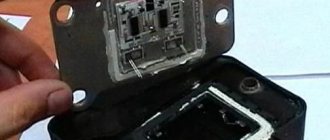
Diagnostics
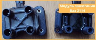
Let's consider several ways. The first of them is visual. A failed part can often be identified by external signs. To do this, take a working element and compare it with a coil whose functionality you doubt. Its body must not have any damage or traces of melting. Smell plays an important role. If the coil smells like burning, it is probably burnt out and needs to be replaced.
Repair of the ignition coil can be performed if its operating temperature does not exceed 150⁰C. Otherwise, it needs to be changed. However, according to the experience of many car enthusiasts, it is not advisable to repair this element. Exceptions are situations when the driver seeks to improve the ignition system. In other cases, it is much safer to purchase a new part.
Another way to identify problems is similar to the “scientific poking” method. This test of the ignition coil involves disconnecting the terminals one by one while the engine is running. Although this method may seem barbaric to many, it helps to quickly identify a faulty coil.
By disconnecting the wire from the coil, the discharge will stop flowing into the fuel combustion chamber and engine operation in this cylinder will be disrupted. A failure can be easily determined by the sound and rhythm of the motor. If there is no change in engine operation when the next coil is turned off, this is a faulty part.
How to set the ignition yourself?
Precise ignition adjustment on the VAZ 2115 injector is performed using a special strobe light. If this is not possible, you can set the ignition on the VAZ by spark.
To do this, follow these steps:
- First of all, the engine is warmed up until it reaches operating temperature.
- The distributor does not need to be removed, but only relaxed.
- You need to remove the central wire from the distributor.
- The piston in the 1st cylinder must be at TDC (the marks are set differently on 8 and 16 valve engines).
- Now you need to hold the short-circuit wire with your left hand and turn on the ignition.
- Use your right hand to adjust the distributor counterclockwise, while keeping the high-voltage wires above the metal.
- Then similar actions are performed, turning the distributor clockwise until a spark appears.
- At this point, the alignment ends, and the distributor is fixed in its regular place.
With the ignition set correctly, the car will operate without interruption with optimal fuel consumption and maximum power.
Loading …
Ignition switch and features of its replacement
ZZ plays an important role in the vehicle's SZ, both for an 8-cl and 16-cl engine. It is activated when the starter is working, thanks to it the lighting, turn signals, and power windows work.
Scheme ZZ VAZ 2115
Replacement or repair of the VAZ 2115 ignition switch may be required if:
- lost or broken keys;
- the lock was damaged during an attempted theft;
- the 3Z cylinder is faulty;
- The contact group does not work.
Ignition switch VAZ 2115
To replace you will need: a set of keys, a hammer, screwdrivers, a thin chisel.
The replacement procedure consists of the following steps:
- The car's power is turned off by disconnecting the negative terminal from the battery.
- We remove the steering wheel.
- Next you need to remove the steering column switches.
- Then you need to loosen the bolts securing the clamp that holds the ZZ on the steering column. If the heads are cut off, the bolts should be carefully knocked out using a hammer and a thin chisel.
- Now you need to disconnect the wiring harness.
- Next, you need to completely unscrew the bolts from the 3Z housing and you can remove it.
- A new device is installed in place of the old one.
- Assembly is carried out in reverse order.
After assembly, you should start the engine and check the operation of the switch (the author of the video is the MY LADA channel).
Electrical diagram of VAZ-2115-01
Years of production 2115: 1997—2012. This is a circuit with a regular button for rear fog lights (with locking), a fluorescent interior light, a connector for the clock and an 8-pin connector for the injector wiring.
1 — block headlights; 2 — fog lights; 3 — air temperature sensor; 4 - generator; 5 — electric motor of the engine cooling system fan; 6 — fan motor activation sensor; 7 — engine compartment lamp switch; 8 — block for connection to a single-wire type audio signal; 9 — sound signal; 10 — oil level sensor; 11 — front brake pad wear sensors; 12 — washer fluid level sensor; 13 — spark plugs; 14 — ignition distributor sensor; 15 - switch; 16 — carburetor solenoid valve control unit; 17 — carburetor solenoid valve; 18 — carburetor limit switch; 19 — speed sensor; 20 - starter; 21 - battery; 22 — relay for turning on fog lights; 23 — coolant level sensor; 24 — brake fluid level sensor; 25 — reverse light switch; 26 — coolant temperature indicator sensor; 27 — engine compartment lamp; 28 — windshield wiper gearmotor; 29 — oil pressure warning lamp sensor; 30 — block for connecting to the rear window washer electric motor; 31 — electric motor for windshield washer; 32 — ignition coil; 33 — instrument cluster; 34 — mounting block; 35 — brake light switch; 36 — blocks connected to the injection system wiring harness; 37 — ignition switch unloading relay; 38 — ignition switch; 39 — glove box lighting lamp; 40 — switch for the glove compartment lighting lamp; 41 — rear window heating switch; 42 — fog light switch; 43 — fog light switch; 44 — external lighting switch; 45 — alarm switch; 46 — steering column switch; 47 — instrument lighting regulator; 48 — hydraulic corrector scale illumination lamp; 49 — socket for a portable lamp; 50 — side direction indicators; 51 — switches in the front door pillars; 52 — lamp for individual interior lighting; 53 — electric heater fan; 54 — additional resistor of the electric heater fan; 55 — heater electric fan switch; 56 — backlight lamp for the electric heater fan switch; 57 — backlight lamp for heater control levers; 58 — display unit of the on-board control system; 59 — trip computer; 60 — switches in the rear door pillars; 61 — block for connection to the clock; 62 — electric fuel pump with fuel level sensor; 63 — ashtray lighting lamp; 64 — cigarette lighter; 65 — trunk lighting; 66 — trunk light switch; 67 — interior lamp; 68 — parking brake warning lamp switch; 69 — external rear lights; 70 — internal rear lights; 71 — plugs for connecting to the rear window heating element; 72 — license plate lights; 73 - additional brake signal.
See the complete diagram in one file below (click to enlarge):
There is a harness for the carburetor ignition system with a speed sensor; it is not connected to the injector. The 4th wire of the interior lamp is the ignition, so that when the ignition is turned on, the backlight goes out immediately. Jumper on Ш11 for wipers. On 2109 they are powered through a fuse on the motor (6-pin), here it is not used and therefore there are 5 wires going to the motor.
Circuit 2115 with “high” panel 21083 is similar to circuit 21099 (except for the rear harness).