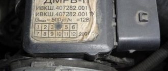
DMRV of VAZ 2115 car
VAZ 2115 cars are the last link in the Samara family and inherited the range of engines from it. Accordingly, the engine ECU controllers and the mass air flow sensors combined with them are similar. Flow meter compatibility is determined by the ECU type, and is as follows:
- ICE VAZ 2111 - Mass air flow sensor 0 280 218 004 (obsolete) or 0 280 218 037, environmental standard Euro 2;
- ICE VAZ 21114 - MAF 0 280 218 116, environmental standard Euro 2;
- ICE VAZ 211183 - Mass air flow sensor 0 280 218 116, environmental standard Euro 3.
Actually, ecology is not related to the type of flow meter; exhaust toxicity is set by the settings of the ECU controller.
What mass air flow sensors are installed on VAZ
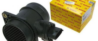
Three types of sensors were installed on VAZ cars with fuel injection systems and HFM5 type air flow sensors from BOSCH, which do not differ in appearance in any way, but are distinguished only by numbers (articles). The first to be installed were sensors ending in 004 - there were few such sensors, so you rarely see them. And the next two: 116th and 037th sensors were installed on most VAZ models.
They differ in that the 116th mass air flow sensor has a smaller error and other operating parameters. Therefore, these mass air flow sensors are not interchangeable, although they are similar in appearance.
There were also Siemens mass air flow sensors, but this article is not about them.
MAF 037 was installed on VAZ 2111, 2112, 2123, 21214, with ECU M 1.5.4, January 5.1-5.1.3, etc.
DMRV 116th on VAZ 21114, 21124, 21214, as well as Kalina and Priora with ECU M 7.9.7 and January 7.2
How does it work
The mass air flow sensor reports to the ECU data on the mass of air flow, which changes following changes in the opening angle of the throttle valve (therefore, the device is placed in close proximity to the throttle).
Having processed the information, the ECU controller commands the injectors to inject a certain amount of fuel. As a result, the engine always runs efficiently and economically.
The design of the mass air flow sensor of VAZ 2115 cars is simple and reliable: a precision resistor sets the reference resistance, paired with it in a bridge circuit is a variable resistor made of platinum wire. Its indicators change with temperature changes. Both sensors are located in the air flow. The variable resistor is heated by a precisely selected voltage. To compensate for cooling, the voltage value is constantly changing to ensure the desired temperature.
The voltage readings (signal from the VAZ mass air flow sensor) are analyzed by the ECU, and, according to a calibrated schedule, the volume (more precisely, weight) of air in kg per unit of time is determined.
Repair manuals and catalogs for the VAZ 2114 car
These manuals and catalogs can be downloaded and saved to your gadget.
- CATALOG OF PARTS AND ASSEMBLY UNITS VAZ 2114, 2113, 2115. —
- 266 pp.
- Size – 7,448 MB
- Format - pdf
- 2002
- 2002
What happens if the mass air flow sensor is faulty
The ECU controller will stop receiving or receive distorted air mass data, resulting in the fuel-air mixture being formed incorrectly. The result is a loss of power and torque (in VAZ cars these parameters are not too high anyway), as well as an increase in fuel consumption.
Signs of a malfunction of the mass air flow sensor - absence or incorrect value of the information signal from contact No. 5 of the sensor connector. If the sensors break down, an overestimation of indicators is first observed (up to 25%), then a complete cessation of information output. This leads to the following symptoms:
- on a cold internal combustion engine, the speed is increased by at least a third;
- with a sharp release of gas, the speed first remains at the same level, then slowly decreases;
- fuel consumption increases significantly;
- the car may stall immediately after starting;
- lacks acceleration dynamics and traction under load.
Table of readings of mass air flow sensor HFM5 VAZ
0.996 – 1.02 – Good sensor readings
1.02 – 1.3 – The sensor is already close to “death”
1.035 and higher - the sensor is not working properly.
However, it is worth noting that for mass air flow sensors with other articles, these indications are different:
| vendor code | Voltage (Volts) |
| 0 280 217 121 | 0,99 – 1,03 |
| 0 280 218 080 | 1,03 – 1,07 |
| 0 280 218 081 | 1,03 – 1,07 |
| 0 280 218 082 | 1,03 – 1,07 |
| 0 280 218 083 | 1,03 – 1,07 |
| 0 281 002 429 | 1,02 – 1,06 |
| 0 281 002 757 | 1,13 – 1,17 |
The main reason why the sensor starts to work incorrectly and its voltage deviates from the norm is contamination of the sensitive element. In this case, the reaction speed of such a sensor is noticeably reduced, and engine operation is disrupted. But contamination occurs primarily due to untimely replacement of the air filter and non-tightness of the filter housing.
However, when checking the sensor, you should not pay attention only to the readings with the car turned off. It is also necessary to check the readings at idle speed. It is important that they change, since there are cases when, when the ignition is turned on, the mass air flow sensor shows the ideal 1.0 Volt, but when the engine starts, the sensor does not see the air flow and the voltage remains unchanged.
For information about what readings should be found, see the documentation for the controller installed on the vehicle. And it’s better to look not at the voltage, but at the flow rate in kg/hour. For example, on most VAZ family cars with HFM5 type air flow sensor at idle, air consumption should be in the range of 7-12 kg/h. There have also been cases when the sensor initially shows 1.0 Volt, and at startup the mass air flow rises to 100 kg/h. In this case, the fuel-air mixture is enriched.
Causes of malfunctions
In 90% of cases, this is contamination of sensitive sensors.
- a low-quality (not certified) or incorrectly installed air filter allows dust to enter the mass air flow sensor measuring channel;
- when operating the vehicle in wet weather or driving through puddles, droplets of water may enter the intake manifold;
- If the crankcase ventilation system does not work (damaged hoses, broken valve), drops of oil enter the air duct pipe.
A dirty sensor can be cleaned or even washed.
Important! Mechanical impact (brushes, cotton swabs) and the use of aggressive agents (acetone, gasoline) are not allowed.
For small amounts of dirt, blowing with compressed air is sufficient. If the air attack does not help, use a special aerosol cleaner for carburetors and mass air flow sensors.
Before reinstallation, the flowmeter must be allowed to dry in the open air.
Cleaning the air flow sensor
As noted earlier, the mass air flow sensor cannot be repaired.
But some craftsmen manage to clean it, thus extending the service life of the monitoring device in question. Moreover, some claim that they have done this more than once. In reality, it is worth recognizing that the chance of repair is quite low. However, if you take into account that the cost of a new sensor is quite high, and an attempt to revive the old one generally requires nothing but time, then you should try.
To clean the air flow sensor you will need:
- composition for cleaning carburetors;
- soft brush;
- Phillips screwdriver.
The sensor is disassembled and the inside of the tube and the platinum wire itself are carefully cleaned. Next, all parts must be left to dry. During this time, remove the throttle entirely and also clean it of any plaque inside. Do not remove the cable from the gas pedal. The assembly is placed on a clean rag and washed with carburetor fluid. You will also need to clean the idle speed regulator and the surrounding area from dirt. If you manage not to damage the wire in the mass air flow sensor, then eventually the problem will become less acute for some time. It is important that the sensor is not damaged mechanically.
Finally, it is worth noting that to increase the service life of the sensor, first of all, it is necessary to replace the air filter on time.
How to check the flow meter on a VAZ 2115 yourself
- If the “Check Engine” light comes on on the dashboard, you can determine errors using OBD codes using a car scanner. However, such equipment is not always at hand.
- The initial check can be carried out by simply disconnecting the flow meter connector and comparing the behavior of the engine with and without the mass air flow sensor. After disconnecting a working sensor, the car's behavior should worsen. A broken flow meter when disconnected will not change the operation of the motor.
- And finally, a relatively accurate test using a multimeter. It is carried out in two stages. First, the power supply to the device is checked with the disconnected connector. From the ECU, 12 volts should be supplied to pin 2, and 5 volts to pin 4. Measurements are made relative to weight, with the ignition on and the engine turned off. Then the voltage of the sensor signal is measured at the connected connector in a resting state (ignition on, engine not running). To do this, you need to equip yourself with a relatively accurate multimeter that can measure voltage with an error of up to 1/100 volt.
Regarding ground, there should be a voltage of 0.99 to 1.02 volts at pin No. 5. It is possible to increase the value to 1.05 volts, but this indicates a high degree of wear on the mass air flow sensors.
The principle of operation of the HFM5 mass air flow sensor from BOSCH on a VAZ
The main measuring element in the sensor is a film or wire element heated to a certain temperature. Due to the air flow, this element is cooled, and the microcircuit (usually built into the sensor itself) tries to maintain the same set temperature. And so, depending on how much power is required to heat a given element, the air passing through is calculated. Flow information is transmitted to the ECU in the form of an analog voltage, and in some sensors in the form of a pulse frequency.
Measurements of air flow in the mass air flow sensor are carried out within 0...5 V. At the moment when the car is turned off and the ignition is turned on, the ADC signal from the sensor should be within 1 V. Readings within 0.996 - 1.0 V are considered ideal. 1.02 - 1.025 are still allowed, and a voltage greater than 1.035 already indicates that the measuring element is dirty or has failed for other reasons.
Purpose
The mass air flow sensor is designed to count the air passing through it. To operate an internal combustion engine, you need not only fuel, but also air, and for uniform and stable operation of the internal combustion engine, fuel and air must be mixed strictly within certain parameters to form a fuel-air mixture. The air passing through the sensor is counted by a special sensing element, which transmits these readings to the engine control unit. In turn, the ECU sends signals to the fuel pump and injectors to increase or decrease the fuel supply depending on the amount of air entering the engine, and the air-fuel mixture is formed in the required parameters.
The principle of operation of the DMRV sensor VAZ 2114, 2113, 2115
DMRV 2114, 2113, 2115 (hot-wire sample) contains a sensing part, a thin mesh (diaphragm) based on silicon, placed in the flow of incoming air. On the grid there is a heated resistor and two thermal sensors located in front of the heated resistor and after it.
The operating principle of the DMRV consists of different readings from two temperature sensors, one of which is located in front of the heating resistor, and three behind it. The heating resistor itself is located on a thin mesh (membrane) based on silicon, mounted in the flow of air passing through the air flow sensor of the VAZ 2114, 2113, 2115 hatchback model 21083-1130010. While the engine is running, the passing air flow cools the part of the mesh located in front of the heating resistor. This causes the heating sensor located in front of the heating resistor to cool down. And the temperature sensor located behind the heating resistor remains warm due to the heated air flow. The differential pulse of these two temperature sensors makes it possible to develop a characteristic curve depending on the size of the air passed through the mass air flow sensor. The pulse created by the air measurement sensor is analog. The MAF signal is a direct current voltage varying in the range from 1 to 5 V. Its size depends on the amount of air passing through it. The ECU, having received a signal from the DMRV VAZ 2114, 2113, 2115, model .21083-1130010, using its data tables, calculates the duration of the opening time of the fuel injectors. The duration of the fuel injector opening pulse corresponds to the parameters of high air consumption
Important ! Various diagrams of the VAZ 2114 car
Design
The sensor is a cylindrical part made of special plastic that is resistant to high temperatures. The body of the sensor contains a special sensitive element that counts the amount of air entering the combustion chamber of the engine. A special mesh is installed in front of this element, which prevents the entry of large debris that can damage not only the sensor, but also the internal combustion engine itself.
The sensor has a connector for connecting a control circuit with 4 pins. The connector is connected to the sensor on one side, and on the other to the engine control unit.
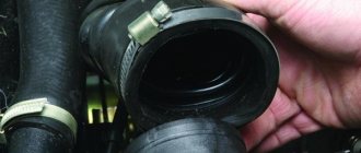
Location
The mass air flow sensor works directly with the air supplied to the engine; AvtoVAZ engineers, when designing the VAZ 2115, acted rationally and placed the mass air flow sensor near the air filter, namely behind it. The sensor is attached to the air filter box through two 6 mm bolts, and on the other side, an inlet corrugation is put on the sensor and secured through a clamp.
Installation location of mass air flow sensor on VAZ 2114, 2113, 2115
DMRV VAZ 2114, 2113, 2115 8 valves are attached to the air filter housing, on the one hand, and to a flexible rubber pipe, on the other hand. It is located between the atmospheric filter and the throttling device,
| Item no. | Explanation of the position on the diagram |
| 1 | crankshaft sensor mounting point (in the cylinder block boss) |
| 2 | sprayers |
| 3 | throttle body and freewheel regulator (located on the air damper body) |
| 4 | dprv |
| 5 | DMRV VAZ 2114, 2113, 2115 |
| 6 | canister venting valve |
| 7 | dtozh |
| 8 | ignition module (salenoid) |
| 9 | spark plugs with caps of high-voltage wires put on them |
| 10 | dd |
Important ! Coolant temperature sensor VAZ 2114, 2113, 2115 model 2112-3851010 It, like the crankshaft sensor, greatly influences the start and operation of the engine of the VAZ 2114, 2113, 2115
Symptoms of a problem
The mass air flow sensor is one of the most expensive sensors in the VAZ 2115 and it extremely rarely fails; breakdowns of this sensor can be observed after 100 thousand km. mileage in other cases, sensor breakdowns can only occur due to mechanical influences on it.
If the sensor fails, the following malfunctions are observed:
- Increased fuel consumption;
- Unstable operation of the internal combustion engine;
- No idle speed;
- Engine speed is unstable and fluctuates;
- The car lost power and dynamics;
- Jerks when moving;
- Difficulty starting the engine after idle time;
If your car exhibits similar signs of malfunction, you need to check the mass air flow sensor for functionality.
Sensors, their purposes and malfunctions
Let's now talk in more detail about each of the sensors, let's look at where they are and what they look like.
Idle speed (IAC)
The device is located in the throttle assembly. It is a small induction coil with a needle inside. Depending on the controller readings, one or another voltage is applied to the coil winding and the needle extends a certain distance into the throttle pipe, regulating the air supply. With this, the idle speed is adjusted.
There is no indicator responsible for this sensor. Therefore, if this node fails, then this can be understood by the following “symptoms”:
- The engine stalls at idle or when changing speed;
- “Floating”, unstable idle speed;
- When turning on a cold engine, there is no increased speed.
To replace the sensor, you must turn off the power to the machine's wiring, completely disconnect the throttle assembly, and then remove the sensor from it, after first disconnecting the terminals that supply electricity to it. In place of the old sensor, you need to install a new device and place the throttle assembly in place.
Detonation (DD)
The knock sensor is located between the cylinders on a car engine and reacts when the fuel detonates inside the cylinder. In essence, it is a piezoelectric element. When gasoline detonates, the sensor converts the resulting vibrations into electricity. Current is supplied to the on-board computer and signals a fuel explosion. After this, the ignition timing is automatically adjusted.
If this type of sensor breaks down, the fuel begins to detonate in the engine. To check the device for functionality, you need to disconnect it using a key from its mounting location, connect it to a voltmeter and knock on it. If voltage was applied to the voltmeter, then the unit is working; if not, it is faulty.
Examination
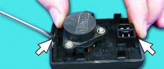
The check is carried out in 2 stages: the first is a visual inspection, the second is a test using a device (multimeter or computer diagnostics). Let's consider each of the options in more detail.
First stage (visual inspection)
To do this, you need to remove the mass air flow sensor and inspect it.
The inspection includes checking:
- Integrity of contacts on the connector;
- Cleanliness inside the sensor;
- Integrity of the sensing element inside the sensor;
- No cracks or chips on the body;
If no damage is found, you can proceed to the second stage of the inspection.
Second stage (test with device)
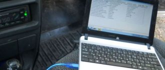
To test the device, you can use computer diagnostics or a multimeter. In most cases, the ELM327 scanner and the OpenDiag program help to diagnose the sensor; you just need to install this program on your smartphone and connect to the scanner via Bluetooth, after which you can check the status of the sensor using the ADC channels.
The test can also be carried out using a multimeter, as this is described in detail in the video.
Checking and repairing at home
There are eight ways to independently check amplitude and frequency mass flow sensors.
Method No. 1 - disabling the air flow meter
The method consists of disconnecting the sensor from the fuel system of the car and checking the functionality of the system without it. To do this, you need to disconnect the device from the connector and start the engine. Without a mass air flow sensor, the controller receives a signal to switch to emergency operation mode. It prepares the air-fuel mixture only based on the throttle position. If the car moves faster and does not stall, it means that the device is faulty and requires repair or replacement.
Method No. 2 - flashing the electronic control unit
If the standard firmware has been changed, then it is unknown what reaction of the controller is programmed in it in case of an emergency. In this case, you should try to insert a 1mm thick plate under the throttle stop. The turnover should increase. Now you need to pull out the chip from the air flow meter. If the power unit continues to work, then the cause of the malfunction is the firmware.
Method No. 3 - installing a working sensor
Install a known good part and start the engine. If after replacement it begins to work better, the motor does not stall, then replacement or repair of the device is required.
Method No. 4 - visual inspection
To do this, use a Phillips screwdriver to unscrew the clamp holding the air collector corrugation. Then you need to disconnect the corrugation and inspect the internal surfaces of the air collector corrugation and the sensor.
Inspection of duct corrugation
There should be no traces of oil or condensation on them, the surfaces should be dry and clean. If you do not take care of the air filter and change it rarely, then dirt can get on the sensitive element of the sensor and cause it to break. This is the most common malfunction. Traces of oil may appear in the flow meter if the oil level in the crankcase is high, or if the oil sump of the crankcase ventilation system is clogged. If necessary, you need to clean the surfaces using special cleaning products.
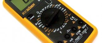
Method No. 5 - checking the mass air flow sensor with a multimeter
To do this, you need to turn on the tester in a mode in which constant voltage is checked. The limit value for measurements should be set to 2V.
DMRV operation diagram
Sensor pinout:
- The yellow wire is located closer to the windshield. It serves as an input for a signal from the flow meter.
- The white-gray wire is the sensor voltage output.
- The black and pink wire leads to the main relay.
- The green wire is used to ground the sensors, that is, it goes to ground.
The wires may have different colors, but their location is unchanged. To check, you need to turn on the ignition, but do not start the car. The red probe from the multimeter must be connected to the yellow wire, and the black one must be connected to ground, that is, to the green wire. We measure the voltage between these two outputs. Multimeter probes make it possible to connect without disturbing the insulation of the wires.
On the new device, the output voltage ranges from 0.996 to 1.01 V.
During operation, this voltage gradually increases and by its value one can judge the wear of the flow meter:
- if the sensor is in good condition, the voltage is from 1.01 to 1.02 V;
- in satisfactory condition - from 1.02 to 1.03 V;
- the sensor resource ends if the voltage is in the range from 1.03 to 1.04 V;
- a value in the range from 1.04 to 1.05 indicates a near-death state; if there are no contraindications, then you can continue to use the sensor;
- if the voltage exceeds 1.05 V, the mass air flow sensor requires replacement.
Indications of the ADC of the flow meter
Diagnostics of the mass air flow sensor "Tseshkoy" is not complicated and can be done with your own hands.
If there is dirt on the removed sensor, you can clean it yourself. You can use WD-40 to wash it. To clean the mass air flow sensor, you must first remove the pipe from it, and then dismantle the device itself. Inside the device there is a mesh and several wires - sensors.
They need to be sprayed with cleaning agent and washed. Then let the liquid dry. If dirt remains, the procedure should be repeated. You need to clean the pipe with the same product. It must be free of dirt and oil stains. After replacing the air filter, all parts must be returned to their place. After the cleaning procedure, the functionality of the device can be restored to 80%, the error about the reduced sensor signal level disappears (the author of the video is “24 hours”).
Flushing the sensor will help avoid costly repairs.
Method number 6 - checking with a scanner
Test method:
- Install a diagnostic program on your phone (smartphone), tablet or laptop computer (for example, Torque Pro, Opendiag, BMWhat, OBD Auto Doctor).
- Connect your mobile device or laptop to the diagnostic connector located on the vehicle's electronic control unit using a special cable, Bluetooth channel.
- Launch the diagnostic utility on your phone (smartphone) or computer.
- Wait until the program finishes scanning all vehicle components. As a result, the utility will check the serviceability of each vehicle unit.
- Decipher the error codes that the program will show after the diagnostics are completed.
To perform this method, testers are used:
- K-Line 409/1;
- Scanmatic;
- ELM (ELM) 327;
- OP-COM.
Method No. 7 - checking by Vasya the Diagnosticist
To identify a malfunction of the mass air flow sensor without removing it from the car, you need to:
- Install a program called “VASYA diagnostician” on your laptop (laptop) and run it.
- Connect the adapter to the vehicle's diagnostic port.
- Select the item “Electronics 1” or “01 – Engine electronics” from the “Control unit” tabs to connect to the vehicle’s control unit.
- Go to “Custom Groups”.
- Select 211, 212 (passport value) and 213 (current value).
- Compare current indicators with passport data. If the deviations are high, then it is necessary to replace the mass air flow sensor.
Method No. 8 - using a motor tester
Good to know
This method is used to test frequency-type flowmeters.
To check the mass air flow sensor with a motor tester (oscilloscope), you need to connect it to the sensor (depending on the car brand) and start the engine.
Mass air flow sensor check parameters:
- transient time when the ignition is on;
- air consumption readings at idle and a sharp increase in engine speed;
- voltage in the sensor network.
It is important to know
The output data is individual for different types of engines. Before diagnosis, you should check the current indications with an official representative.
Replacement
Replacing the sensor is quite simple; all you need is a 10 mm wrench and a Phillips screwdriver.
The replacement process is complete, after this procedure your car should drive like new.
Source
Signs of malfunction of the VAZ-2115 DMVR sensor and its replacement or cleaning
The mass air flow sensor is a special sensor that monitors the mass air flow of the power plant.
Where is this control device located? In the fuel system of the engine, or rather, directly in the intake tract. Experts call it the most important element that ensures proper fuel injection into the engine. This sensor, like any other component, can fail. This article describes how the mass air flow sensor operates on the VAZ-2115 and the possible problems that arise when it fails. We will also tell you about ways to eliminate them.
Why do you need a mass air flow sensor?
This monitoring device is designed to determine the volume of air entering the combustion chambers of the power unit. As you know, without this the engine, in principle, will not be able to work. The manufacturer installed it near the air filter.
During operation, the engine receives 1 part gasoline and 14 parts air. As a result, the most optimal mixture is formed, allowing the power plant to operate as efficiently as possible.
If this proportion is not respected for one reason or another, the following begins to happen:
- excessive gasoline consumption;
- power drop.
Therefore, correct air mass flow is one of the basic conditions for the proper functioning of the vehicle. This parameter is calculated in the ECU based on the MAF readings.
Depending on how hard the driver of the car presses on the accelerator, the air is supplied more intensely. For its part, the mass air flow sensor measures its incoming volumes, and the data is sent to the on-board computer. The latter regulates the flow of gasoline accordingly.
Mass air flow sensor (MAF)
Road transport is constantly being improved. All modifications made to the design of the car are aimed at improving various indicators - increasing power, reducing fuel consumption, improving aerodynamic performance and the level of overall comfort.
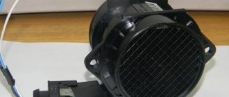
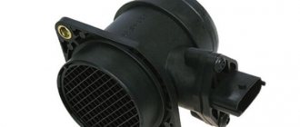
This is what the new mass air flow sensor looks like
One of the main improvements related to reducing fuel consumption was the transition from the use of a carburetor power supply system in favor of an injection system.
The use of a system in which the fuel supply is strictly metered for the operation of the power plant in different modes makes it possible to reduce consumption while ensuring the maximum possible output of power from the power unit.
But in a carburetor system, the system is technologically simpler, since the operation of the main element of this system, the carburetor, is performed mechanically, which ensures high reliability. Also in this power system, the air-fuel mixture is formed in the carburetor and enters the cylinders due to the vacuum created by the pistons.
The injection system is technically more complex. The working mixture is already formed in the cylinders, and the components of the mixture are supplied to them separately. Air, one of the elements of the mixture, is supplied due to vacuum, but fuel is forced into the cylinders by injectors.
The electronic control unit is responsible for the required amount of fuel required to be supplied to the cylinders.
But in order to correctly dosage, the control unit must know such parameters as the position of the crankshaft and its rotation speed, the amount of air entering the cylinders, the amount of air remaining in the exhaust gases, and the position of the throttle valve. These parameters for calculating the amount of fuel supplied are met by sensors installed in certain elements of the power plant.
Mass air flow sensor. Types
Let's consider a sensor responsible for providing information about the amount of incoming air - a mass air flow sensor (MAF, air flow meter).
Schematic design of an air flow meter
The mass air flow sensor is always located in the air pipe, next to the air filter, its task is to determine the air flow at the outlet of the filter. There are several types of mass air flow sensors.
- The first air flow meters were based on a pitot tube; their second name was blade flow meters. The main element of such a sensor was a thin plate, softly fixed. The air flow, in the path of which the sensor is located, begins to bend the plate. The potentiometer included in the circuit measures the degree of bending of the plate, while the resistance of the potentiometer changes - it is the change in the resistance of the potentiometer that acts as a signal for the amount of air supplied to the control unit.
- More modern and most common are sensors using plate hot-wire meters. In such a flow meter, the main element is a heat exchanger with two thin platinum plates. Energy is supplied to these plates to heat them, one of them is the working plate, the second plate is the control one. The operation of the mass air flow sensor is based on maintaining the same temperature on both plates. It works like this: the air flow, passing through the heat exchanger, begins to cool the working plate. In order to maintain a temperature on the working plate identical to the control temperature, a larger amount of current begins to be supplied to it. The change in the amount of current acts as an indicator for the control unit about the amount of air entering the system.
- The third type of mass air flow sensors are flow meters, which use film meters. They use platinum-coated silicon wafers as working elements. MAF data appeared relatively recently, so they are not yet widely used.
Video: Cleaning the mass air flow sensor How to properly remove and clean the mass air flow sensor Everything in detail
The performance of the mass air flow sensor plays a significant role in the correct formation of the air-fuel mixture. Therefore, its malfunctions lead to disruption of the installation or, in some cases, the inability to start the motor.
The failure and failure of this sensor can be identified by the following signs:
- the “Check engine” signal comes on;
- increase in gasoline consumption;
- power drop;
- decreased dynamics of speed gain;
- difficulty starting or inability to start;
- floating speed in idle mode.
Operating principle of the air flow sensor
The sensor is based on a platinum wire only 70 micrometers thick.
It is hidden in a special tube located in front of the throttle valve. When air hits it, the wire cools. To restore normal temperature, a certain charge of electricity passes through it, according to the size of its ECU, and finds out exactly how much fuel the engine needs at the moment. Due to the fact that air comes directly from the atmosphere, dirt regularly settles on the wire. It is this that, for the most part, contributes to the fact that the sensor becomes unusable. The latest models of mass air flow sensors, however, have an automatic cleaning system.
DMRV failure - how to identify
If this control element fails, a lamp lights up on the dashboard, signaling the need to check the car’s power plant.
The main signs of failure of the mass air flow sensor:
- power is lost;
- the speed also drops;
- a lot of fuel is consumed;
- the engine starts poorly.
There are several ways to determine the performance of the mass air flow sensor:
In the first case, replacing the sensor is not difficult. Just disconnect the connector (pinout is not required here) and turn on the engine. The ECU must go into emergency mode. In this case, the supply of the combustible mixture is regulated only by the throttle valve. At the same time, at idle, the power unit produces 1.5 thousand revolutions. Next, you will need to drive a certain distance. If the car accelerates faster than usual, we can confidently say that the mass air flow sensor has broken down.
It is also worth pointing out that the multimeter is useful only if the car is equipped with a sensor manufactured by. The check goes like this:
- The scale on the tester is set to 2 volts of DC voltage;
- the red probe is attached to the yellow wire, the black one to the green;
- turn on the ignition.
If the readings are within:
- 1.02 volts - then the sensor is working;
- 1.03 – acceptable value;
- 1.05 is the limit.
In cases where the measured voltage is higher, a breakdown should be considered. In order to determine from the appearance of the control device whether it is working, you will need to carefully examine the tubes leading to it from the inside. They are easy to dismantle using a Phillips screwdriver. First of all, unscrew the clamp securing the corrugated sleeve. The surface of this tube must be clean, without oily films.
The presence of dirt inside the sensor is a clear sign of its malfunction. As a rule, the problem occurs when the car owner forgets to change the air filter on time.
Oil leaks are usually evidence of excess lubricant in the system or improper operation of the shut-off valve. Such contamination significantly reduces the service life of the mass air flow sensor.
Then it is necessary to dismantle the sensor itself. To do this, you need to use a 10mm socket wrench. After the control device is removed from the filter, it will need to be inspected. In a situation where the rubber gasket of the sensor remains in place, then we can speak with almost one hundred percent certainty about a breakdown of the mass air flow sensor.
Where is the mass air flow sensor located?
The mass air flow sensor on the VAZ 2114 is located in the air duct located behind the air purification filter. A wiring harness is connected to the sensor, ending with a plug.
Sensor design features
The VAZ 2114 can use mass air flow sensors of domestic and imported origin. The design of the devices is the same and corresponds to the diagram below.
The DMRV includes:
- 1 — block for connecting the wiring harness;
- 2 — sensor operation controller;
- 3 - measuring element;
- 4 — outer body;
- 5 — metal protective mesh;
- 6 — guide deflector;
- 7 — fastening the sensor body to the body;
- 8 — direction of air flow.
What is the optimal air flow for VAZ 2114 cars?
The amount of air required to form the mixture depends on the speed:
- at idle speed (850-950 rpm) - 9.5-10.5 kg of air per hour;
- at medium speed (2000 rpm) - 19-21 kg of air per hour.
Reducing the air supply leads to a leaner mixture, and increasing it leads to a richer mixture.
Small deviations in measurement accuracy have little effect on the operation of the engine, but with errors of 2-3 kg, the engine begins to operate unstably.
Some control units compensate for measurement inaccuracies based on data from other sensors. For example, the January 5.1 block additionally adjusts the mixture composition based on the signal from the lambda probe.
The main causes of failure of the mass air flow sensor
The most common causes of sensor failure are:
- dust ingress;
- oil contamination;
- short circuit of the wiring due to damage to the insulation or plug;
- mechanical damage to active elements.
A common cause of incorrect operation of the mass air flow sensor is the failure of electronic components, which increases the sensor’s response time to changes in air flow.
A working sensor monitors changes at a speed of 0.5 ms, and if it breaks down, the response time increases by 20-30 times. The defect is detected only by recording the operation graph with an oscilloscope.
Such a sensor cannot be repaired; it must be replaced with a new one.
What factors disable the mass air flow sensor?
Factors causing failure of the air flow sensor:
- Dust may be caused by improper installation of the sensor on the filter, which causes the sealing ring to become distorted. With this defect, a thin coating of contamination will be present on the sensor input grid. Another cause of dust is a clogged air filter, so regular maintenance will prolong the life of the air flow sensor.
- Oil is thrown onto the sensor if the level in the crankcase is high or if the oil separator in the ventilation system is clogged. An additional negative factor is engine wear, which causes lubricant to actively enter the crankcase ventilation.
- Contact with sharp objects on the insulation, oiling. Such impacts are the result of careless repairs.
- Damage to the sensor is possible during vehicle maintenance (impacts to the body) or during improper cleaning of the active part.
Characteristic signs of failure of the mass air flow sensor
Symptoms of DMRV malfunctions:
- Unstable engine operation at idle;
- reduction in acceleration dynamics;
- spontaneous change in speed in all operating modes;
- difficulty starting;
- Check Engine light turns on.
If an additional trip computer is installed on a VAZ 2114 car, then during diagnostics, in addition to direct sensor errors, codes indicating misfires and lean mixture conditions are possible.
How to check the mass air flow sensor yourself?
To independently check the sensor, there are several methods based on disconnection, as well as inspection and testing with a multimeter. There are no other diagnostic methods at home.
A thorough inspection of the mass air flow sensor is carried out on a special stand, which makes it possible to record sensor problems under various operating modes.
Another common testing method is to install an identical device removed from another vehicle.
Disabling the mass air flow sensor
The easiest way to check the mass air flow sensor on a VAZ 2114 is to disconnect the plug. If there is no signal, the engine control unit goes into emergency operation mode, determining the approximate air volume based on the throttle position.
At the same time, fuel consumption increases slightly - for the VAZ 2114 it reaches 10-12 liters per 100 km. A characteristic feature is the increase in idle speed to 1500 rpm. But when using the controller January 7.2. or Bosch M7.9.
7, the idle speed does not increase due to software features.
Visual inspection
External inspection requires removal of the air duct from the sensor. During the inspection, the dustiness of the inside of the housing and the corrugated air supply hose is assessed. There should be no traces of oil or dust on the surface.
Checking the device with a multimeter
- The purpose of diagnostics is to measure the voltage supplied by the sensor.
- Bosch products are checked in a similar way:
- 0280218004;
- 0280218037;
- 0280218116.
To measure you will need:
- test device:
- a set of measuring probes;
- WD-40 liquid.
The measurement is made between the yellow and green wires. Voltage values can be displayed on the screen of some on-board computers (menu voltage from sensors, U Mass air flow sensor).
Checking the mass air flow sensor using a multimeter is demonstrated in the video from “IZO))) LENTA”.
Determining the pinout of the mass air flow sensor
The location of the wires in the block starting from those closest to the windshield:
- yellow - positive input signal (in diagram 7);
- gray-white insulator - positive power signal (in diagram 12);
- green — sensor grounding (in diagram 30);
- pink-black insulator - sending a signal to the main relay.
Other colors of wiring insulation are possible, but the pinout sequence remains unchanged.
Instructions for testing
Measurement sequence:
- Insert the probes into the connector to the places where the wires are installed. To facilitate the procedure, the probes are lubricated with WD-40 liquid. The positive signal comes from the yellow wire, the negative signal from the green wire. It is not recommended to pierce the insulation and use additional cables, as this reduces the accuracy of the measurement.
- Switch the multimeter to DC voltage measurement mode with a limit value of 2.0 volts.
- Turn on the ignition, do not start the engine.
- Measure the voltage and compare it with the required value.
Comparison of test results with established standards
In accordance with the table, the sensor state is determined based on the measurement results.
| Voltage, V | Sensor status |
| 0,996-1,01 | New sensor |
| 1,01-1,02 | Working condition |
| 1,02-1,03 | Beginning of sensor wear |
| 1,03-1,04 | It is advisable to replace |
| More than 1.04 | Sensor is faulty |
How to restore the mass air flow sensor?
The optimal solution for problems with the mass air flow sensor is to replace the faulty sensor with a new one. But since the cost of the device is about 2500-3900 rubles, many owners are trying to “revive” the old part.
There are four recovery methods:
- installation of additional resistance;
- blocking part of the air supply channel to the thermistor with aluminum tape;
- updating the engine control unit firmware;
- washing the sensor body and housing from dirt.
Installing additional resistance
Additional resistances are installed in the circuit connecting the sensor to the control unit. When an electric current passes, the voltage decreases, which can be brought to the required limits. The resistance value is selected experimentally. Most often, a 1 kOhm resistor is soldered to the yellow wire and a 15 kOhm element to the green wire.