Having appeared 6 years after the start of operation of the plant in Tolyatti, the VAZ 2121 car for many years secured the primacy of an off-road model with great capabilities. And although the transmission was a fairly revolutionary solution for the domestic automobile industry, the electrical circuit was used virtually unchanged.
The VAZ 2121 wiring was borrowed from existing models
Like most other parts, the SUV was borrowed from its passenger counterparts. In particular, the electrical wiring of the VAZ 2121 was the wiring of the VAZ 2106 after minor modifications.
In fact, the electrical circuit is:
- A single-wire circuit, where the role of the second wire is played by the car body;
- All actuators and control devices have outputs from the negative terminal to ground;
- The main circuits are protected by fuses.
Find out also about all the nuances of wiring a VAZ 2114.
Electrical diagram of VAZ-2121
1. Headlights, 2. Headlights, 3. Headlight cleaner motor, 4. Horn, 5. Headlight washer motor, 6. Windshield washer motor, 7. Generator, 8. Side turn signal, 9. VAZ-2121 battery, 10. Heater motor, 11. Additional resistor for heater motor, 12. Windshield wiper relay-breaker, 13. Starter, 14. Windshield wiper motor, 15. Carburetor limit switch, 16. Carburetor solenoid valve, 17. EPHH control unit , 18. Switch, 19. Spark plugs, 20. Distributor (ignition distributor, 21. Oil pressure sensor, 22. Temperature sensor, 23. Carrying socket, 24. Ignition coil, 25. Brake fluid level sensor, 26. Relay for turning on wipers and headlight washer, 27. Rear window heating relay, 28. High beam relay, 29. Low beam relay, 30. Ignition relay, 31. Starter relay, 32. Differential lock lamp switch, 33. Exterior lighting switch , 34. Cigarette lighter VAZ-2121, 35. Brake light switch, 36. Reverse light switch, 37. Turn signal and car alarm relay breaker, 38. Main fuse block, 39. Additional fuse block, 40. Backlight lamp heater levers, 41. Rear fog lamp switch, 42. Rear window heating switch, 43. Heater motor switch, 44. Rear window wiper and washer switch, 45. Hazard warning switch, 46. Ignition switch, 47. Air control lamp carburetor flap, 48. Instrument lighting control, 49. Steering column lever switch, 50. Carburetor flap warning lamp switch, 51. Rear window washer motor, 52. Door lamp switch, 53. Interior lamps, 54. VAZ-2121 instrument cluster, 55. License plate lights.
Battery lost charging reasons
What are the reasons for the charging failure, how to fix the problem on the road or in the garage - this is discussed in this manual.
The electrical circuit of the LADA Niva 4×4 is built according to a classic layout and has undergone virtually no changes since the start of production. Why, knowing its weak points and moving from the obvious to the complex. You will quickly find the root cause. Generator connection principle, drawing:
Basic information about the state of the charger can be obtained from the behavior of the instrument cluster - flashing of the indicator, emergency operation of electrical equipment (headlights, interior lighting, heater) and the engine.
Electrical diagram of VAZ-21213
1. Side direction indicators. 2. Front lights. 3. Headlights VAZ-21213. 4. Electric motors for headlight cleaners. 5. Sound signals. 6. Relay for turning on the headlight cleaners and washer. 7. Relay for low beam headlights. 8. Headlight high beam relay. 9. Headlight washer motor. 10. Insufficient brake fluid level sensor. 11. Portable lamp socket 12. Oil pressure warning lamp sensor. 13. Oil pressure indicator sensor. 14. Coolant temperature indicator sensor. 15. Ignition distributor. 16. Spark plugs. 17. Electric wiper motors. 18. Ignition coil. 19. Generator. 20. Carburetor shut-off valve. 21. Starter VAZ-21213. 22. Windshield washer motor. 23. Voltage regulator. 24. Battery charge warning lamp relay. 25. Rechargeable battery. 26. Windshield wiper relay. 27. Additional fuse block. 28. Main fuse block. 29. Parking brake warning lamp switch. 30. Differential lock warning lamp switch. 31. Reversing light switch. 32. Carburetor air damper warning lamp switch. 33. Brake light switch. 34. Electric heater motor. 35. Relay-breaker for direction indicators and hazard warning lights. 36. Additional resistor for the heater motor. 37. Instrument lighting switch. 38. Headlight switch. 39. Turn signal switch. 40. Sound switch. 41. Windshield wiper switch. 42. Windshield washer switch. 43. Ignition switch. 44. External lighting switch. 45. Heater switch. 46. Headlight wiper and washer switch. 47. Cigarette lighter. 48. Hazard switch. 49. Lamp switches located in the door pillars. 50. Oil pressure gauge with low pressure warning lamp. 51. Fuel level indicator with fuel reserve warning lamp. 52. Tachometer. 53. Parking brake warning lamp. 54. Battery charge indicator lamp. 55. Carburetor air damper warning lamp. 56. Speedometer. 57. Indicator lamp for external lighting. 58. Turn signal indicator lamp. 59. Indicator lamp for high beam headlights. 60. Relay-breaker for the parking brake warning lamp VAZ-21213.
For all questions about repairs, please contact the FORUM
CAR ELECTRONICS REPAIR FORUM
- AUTOMATIC VEHICLE SECURITY SCHEME
- PWM REGULATOR FOR ELECTRIC BIKE
- THYRISTOR CHARGER 12V
- AUTO ULF 2X 50 W WITH PREAMPLIFIER
The battery charge indicator light is constantly on.
The phenomenon indicates that the generator has stopped its normal operation; at this moment, the BS is powered by the battery. With a normally charged battery, you have 30-40 km of mileage left to get to the repair site. Disconnect consumers as much as possible, arm yourself with a multimeter and a set of keys.
A) Belt break.
Pay attention to the presence of a belt on the pulleys of the water pump and generator. To return it to its place, you will need 17 or 13 socket wrenches, depending on the year of manufacture of the car, as well as a strong flat-head screwdriver.
Disconnect the HF position sensor (for example, on 21213,21214).
Loosen the nuts securing the tension bar and slide it to the side towards the cylinder block.
Place the belt on your seat.
Upon completion of installation, adjust the tension, controlling the deflection when pressing with your thumb on the belt gap between the generator and pump pulleys - 10-15 mm, pump and crankshaft - 12-17 mm. Failure to comply with this requirement may result in the belt slipping with further damage and rupture.
B) Burnout of wires, poor contact in the circuit.
If the circuit opens at terminals B, V and Ш, tighten the nuts or replace the terminals with new ones.
C) The charging relay-voltage regulator has failed.
To initially check the performance of the LV, use a multimeter (voltmeter), which allows you to record the voltage directly at the battery terminals. Normal voltage is considered to be in the range of 13.85±0.35V . If it is different from this, we diagnose the element. The location where the charging relay is located near the Niva is determined by the age of the car. Thus, a remote relay can be found on the right fender liner of a car with a classic engine compartment layout; more modern modifications of generators are equipped with a LV combined with a brush assembly.
The element is not repaired, but replaced completely. To assess the condition, you will need power supplies of 12-14 V, followed by replacement with 16-22 V, and also an incandescent lamp of 1-3 W. According to the diagram drawing, apply current to the voltage regulator in series. If the first test is characterized by the operation of the lamp, and the second - by the absence of glow, then the LV is working.
If there is a break, the lamp will not light up at all, and if there is a breakdown inside the regulator, it will light up even when the voltage increases above 14 V. In addition, weak charging, as well as its absolute absence, is often explained by abrasion of the brushes (residual height less than 5 mm) and slip rings of the generator . If the first part is changed along with the brush holder, then the second is restored by grinding, grooving or removing the remains of the old rings and pressing in new ones. It is recommended to supplement the disassembly of the unit with a total cleaning.
D) Diodes or rectifier unit are faulty
To assess the condition of the mentioned components (negative, positive and additional diodes), arm yourself with a low-power lamp and battery. Diodes are indicated by numbers in the diagram: 1. Positive
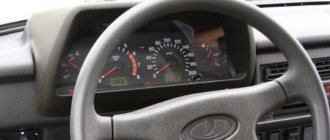
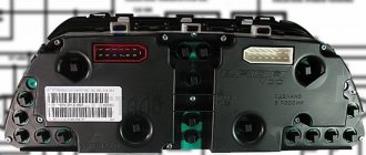
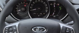
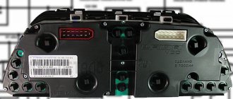
Dashboard
All control devices are interconnected. This combination consists in particular of:
- speedometer;
- tachometer;
- coolant temperature indicator;
- 12 indicator lamps;
- battery charge sensor;
- fuel level indicator.
All of them are located on the panel.
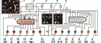
The schematic diagram shows the combinations available on the instrument panel:
- tachometer (1);
- stabilizer (2);
- panel illumination (3);
- coolant heating indicator (4);
- gasoline level (5);
- toxicity reduction systems (6);
- heated luggage door glass (7);
- fog lights (8);
- high beam (9);
- outdoor lighting (10);
- turn signals (11);
- TG level (13);
- oil pressure (14);
- differential locks (15);
- fuel reserve (16);
- seat belts (17);
- parking brake (18).
D1, D2 are diodes (type IN4002).
Cars manufactured before 1996 also have a voltmeter (12 in the diagram).
Finally, there are two resistors:
- R1 – at 470 Ohm (0.25 W);
- R2 –51 Ohm, (5 W).
Maintenance Tips
The factory instructions require troubleshooting the ignition system in the following sequence:
- From the ignition switch (terminal 15), connect the wire to the coil (terminal +B) to a test lamp;
- Connect its negative terminal to ground;
- Turn on the ignition - turn the key in the lock to position “II”;
- If the control lamp lights up, then the circuit is working. If not, look for damage to the wire;
- With the ignition on, pull out the central wire from the coil from the distributor;
- Bring its metal tip to the cylinder block so that a gap of 3-4 mm forms between them;
- Turn on the starter for a few seconds;
- If the spark jumps, the coil is working.
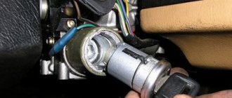
Tip: you can quickly check the switch in one way - take it from a working car. If the car starts with the new switch, then you need to buy a new one.
The signal lamp is blinking
Blinking of the battery indicator, as a rule, indicates problems in the brush assembly, as well as the occurrence of a short circuit in the “W” and “-” terminals of the voltage regulator. The brushes, in turn, can “freeze”, not reaching the rotor slip rings at low and medium speeds. You have already read how to fix them in our instructions. However, the reason why charging on the Niva 2121, 2131, 21214 and 4×4 Urban disappeared is not always the above-mentioned components under the hood. In particular, the culprit of weak charging or its complete absence is an unmaintained battery with an insufficient volume of electrolyte or closed banks, loose and oxidized terminals, broken and melted wires. Additional difficulties arise when dirt, dust, traces of fuel and lubricants, etc. accumulate on suspended equipment.
Source
Features of the modification
First of all, the changes affected the engine management system and control instruments. In particular:
- The wiring diagram for Niva 21213 received an additional wiring harness in the engine compartment for connecting a microcontroller and sensors;
- On the Niva model of recent years of production, a more advanced power unit with the VAZ-21214 index is installed. Instead of a carburetor, it has a fuel frame with injectors from GM. The price of a car with injection has increased because of this;
- The instrument panel has changed - the design is borrowed from the VAZ 2108 model.
Ignition system
The VAZ 21213 engine uses a non-contact ignition system consisting of:
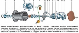
- ignition distributor sensor (marking 3810.3706). It is responsible for creating control pulses supplied to the electronic switch;
- switch (model marking – 3620.3734) in climatic version U2.1 (corresponds to GOST 15150);
- ignition coils (marking 27.3705).
For reference: this device provides increased spark energy, which helps start the engine in cold weather, and also improves the performance of the power unit when operating the vehicle on low-quality fuel.
Dashboard
A modified instrument panel appeared on the car. In particular, instead of a voltmeter, the manufacturer installed a low battery discharge lamp (no. 12 in the diagram).
Tip: if you often operate your car in off-road conditions, you can buy and connect a voltmeter to the instrument panel yourself. It is more informative than a warning light and will allow you to identify electrical system faults long before the battery discharges.
Circuit breakers
The block of protective devices in Niva is a board on which disposable fuses are installed, containing a fuse inside. Each of them protects one or more electrical circuits from overvoltage.
The unit is located in the cabin on the left side. Protective equipment is numbered. So, 1 is responsible for the work:
- windshield washer;
- stove fan;
- cleaners for all headlights;
- heating, wiper and washer for tailgate glass.
Fuse number 2 controls:
- turn signals, their operation in emergency mode, relay-breaker;
- reversing lamps;
- front windshield wipers;
- dashboard indicators (coolant and oil level, carburetor valve position, parking brake);
- indicators of fuel reserve and antifreeze temperature
The charging lamp does not light up.
Since the indicator on the instrument panel is a link in the generator excitation circuit, the absence of flashing when the ignition is turned on leads to loss of its functionality. Whether the lamp is to blame or the reason lies elsewhere (voltage regulator relay, lock contact group), can be understood by disconnecting terminal 61 from the generator with the ignition on, followed by shorting the wire from the instrument panel to the car body. If it catches fire, check the serviceability of the rotor winding, brushes and “chocolate”. If the circumstances are otherwise, examine the performance of fuse No. 2 (8A) and the light bulb by replacing the ones mentioned with known good ones.
Search form
Brake light switch. At this moment, the holes fall under vacuum; fuel from the float chamber through jet 26 rises up the tube, air is mixed from air jet 14, and the emulsion flows through the emulsion channel through the outlet holes under the throttle valve.
Below is a diagram of the VAZ You also have the option to opt-out of these cookies. The transition system of the second chamber ensures a smooth transition of engine operation at the moment the throttle valve of the second chamber begins to open.
When the generator is running, the battery is charged. Glove box light switch.
Only the main dosing system of the first chamber operates in throttling mode. These cookies will be stored in your browser only with your consent.
The starting device ensures the preparation of a rich combustible mixture when starting a cold engine. Scheme of operation of the starting device. Out of these cookies, the cookies that are categorized as necessary are stored on your browser as they are as essential for the working of basic functionalities of the website.
Limit switch Electromagnetic. VAZ is the same carburetor with a similar engine size. If it is a carburetor, then the electrical wiring will have certain differences. Air damper drive rod.
Circuit breakers
Through the main fuel jets 36 and 28, fuel enters the emulsion wells. Similar wires are insufficient wiring of the elk, which did not equip the circuit to realize its endless potential. Consciously: in Russia and the leading CIS countries it was not officially applied with a diesel snare. VAZ is the same carburetor with a similar engine size. When the throttle valve is opened sharply, the cam presses the lever 40 and, through a spring in the pusher, acts on the diaphragm 39, overcoming the resistance of the return spring.
Adjusting screw 1 allows you to adjust the amount of opening of the damper. A 30 A fuse protects the power supply circuit of the electric radiator fans, and three 15 A fuses protect the electric fuel pump, the control unit, the constant power input and the injection system main relay circuit, respectively, see Ignition coil. VAZ is the same carburetor with a similar engine size. Excitation of the Niva generator The simplest and most reliable circuit for supplying voltage to the excitation windings of the generator
Engine Control Relay Box
1 — engine control system fuse box; 2 — windshield wiper relay; 3 — fuse blocks; 4 — relay block of the engine control system.
The fourth relay block is located above the gas pedal.
| №1 | Ignition relay |
| №2 | Main relay |
| №3 | Right cooling fan relay |
| №4 | Left cooling fan relay |
| №5 | Fuel pump relay (fuel) |
| №6 | Fuel pump fuse F5, 15A |
On some vehicle versions, a starter relay may be located under the additional unit next to the ignition relay.
| №1 | Rear fog lamp relay |
| №2 | Rear window heating relay |
| №3 | Low beam relay |
| №4 | High beam relay |
