Depending on the year of manufacture, different types of instrument panels were installed on the domestic SUV. Until about 1998, Niva 4x4s were equipped with instrument clusters made in Hungary, and after Avtopribor LLC (Vladimir and Podolsk). Let's look at the features of these panels in the diagrams.
Niva instrument panel: description of indicator lamps
For the fullest description, we took the shield from the most common version of the VAZ 21213.
| Number | Description |
| 3/4 | The turn indicators turn on simultaneously when the hazard warning lights are activated. |
| 7 | Insufficient fuel level in the gas tank. |
| 8 | The vehicle's side lighting is on. |
| 9 | Emergency situation in the brake system. |
| 10 | The long-range illumination of the head optics is activated. |
| 12 | Vehicle mileage monitor. |
| 13 | Check engine light. If the indicator lights up, you need to carefully check the power plant. |
| 14 | Hazard warning light. |
| 15 | Clock display. |
| 16 | If the lamp lights up, you need to check the generator and battery charging. |
| 17 | Handbrake activated |
| 18 | The engine oil level has dropped critically. |
| 19 | Most configurations include a backup lamp. |
You should also highlight the colors of the car's indicators. They can be divided into three parts.
- Green/blue – indicators of these colors indicate normal operation of machine components.
- Orange/yellow - tells the driver that a certain unit requires attention or service.
- Red is the most dangerous color. If a lamp of this color lights up on the dashboard, the car must be urgently shown to a mechanic.
Exclamation mark on the Niva panel
Indicates that the fluid level in the brake system has decreased. You will need to open the expansion tank cap and add brake fluid to the required level. It is recommended to check the line for leaks and pad wear.
content .. 100 101 102 103 104 105 106 107 108 109 ..VAZ-21213 (Niva). Control devices
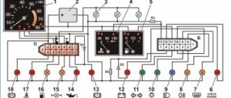
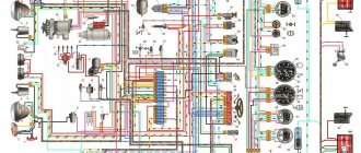
VAZ-21213 (Niva). Connection diagram of the instrument cluster produced before 1996 (rear view)
1 – plug connector block with conventional numbering of plugs; 2 – tachometer; 3 – voltage stabilizer; 4 – instrument cluster lighting lamp; 5 – coolant temperature indicator; 6 – fuel level indicator; 7 – resistor 470 Ohm, 0.25 W; 8 – resistor 36 Ohm, 5 W; 9 – warning lamp of the toxicity reduction system; 10 – control lamp for heated rear window;
| 11 – fog light indicator lamp; 12 – control lamp for high beam headlights; 13 – indicator lamp for external lighting; 14 – indicator lamp for direction indicators; 15 – voltmeter; 16 – brake fluid level warning lamp; 17 – diode IN4002; 18 – oil pressure warning lamp; 19 – differential lock warning lamp; 20 – fuel reserve warning lamp; 21 – seat belt warning lamp; 22 – parking brake warning lamp |
VAZ-21213 (Niva). Connection diagram of the instrument cluster produced after 1996 (rear view)
| 1 – tachometer; 2 – voltage stabilizer; 3 – instrument cluster lighting lamp; 4 – coolant temperature indicator; 5 – fuel level indicator; 6 – warning lamp of the toxicity reduction system; 7 – indicator lamp for heated rear window; 8 – fog light indicator lamp; 9 – control lamp for high beam headlights; | 10 – indicator lamp for external lighting; 11 – indicator lamp for direction indicators; 12 – voltmeter; 13 – brake fluid level warning lamp; 14 – oil pressure warning lamp; 15 – differential lock warning lamp; 16 – fuel reserve warning lamp; 17 – seat belt warning lamp; 18 – parking brake warning lamp; D1, D2 – IN4002 diodes; R1 – resistor 470 Ohm, 0.25 W; R2 – resistor 51 Ohm, 5 W |
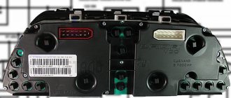
All vehicle control devices are combined into an instrument cluster. It includes: speedometer with trip meter, coolant temperature gauge, fuel level gauge, tachometer, voltmeter with LED indicator and 12 warning lights. In 1996, instead of a voltmeter, a battery charge indicator lamp began to be installed. The instrument cluster is attached to the front panel of the car with two nuts. The connections of the instrument cluster are made by printed wiring on a board made of foil getinax. The board is attached to the back of the case. Connection diagrams for the instrument cluster (manufactured before 1996 and after 1996) are shown in the figures. The speedometer has two trip counters: one total, and the second “daily”. The readings of the second counter can be set to zero using a handle placed through the glass of the instrument cluster. The daily counter can only be reset while the vehicle is stationary by turning the handle clockwise. Warning
To avoid damaging the glass of the instrument cluster, do not clean it with any solvents.
7.12.1.
VAZ-21213 (Niva).
Removing and installing the instrument cluster Removal and installation
1. Open the hood and disconnect the wire from the negative terminal of the battery. 2. Remove the instrument panel shield by unscrewing the two screws securing it from below, and then pull the lower edge of the shield towards you and release the upper latches. 3. Unscrew the two fastening nuts and remove the instrument cluster from the instrument panel socket. 4. Disconnect the wires and the flexible speedometer drive shaft from the instrument cluster. 5. Install the instrument cluster in the reverse order of removal. During installation, do not allow loops or kinks in the flexible shaft, leading to residual deformation of its shell. After installing the instrument cluster, the flexible shaft should not have any sharp bends. The bending radii of the shaft shell in the mounted state must be more than 100 mm.
7.12.2.
Disassembling and assembling the instrument cluster Removal and installation
1. Open the hood and disconnect the wire from the negative terminal of the battery. 2. Remove the instrument panel shield by unscrewing the two screws securing it from below, and then pull the lower edge of the shield towards you and release the upper latches. 3. Unscrew the two fastening nuts and remove the instrument cluster from the instrument panel socket. 4. Disconnect the wires and the flexible speedometer drive shaft from the instrument cluster. 5. Install the instrument cluster in the reverse order of removal. During installation, do not allow loops or kinks in the flexible shaft, leading to residual deformation of its shell. After installing the instrument cluster, the flexible shaft should not have any sharp bends. The bending radii of the shaft shell in the mounted state must be more than 100 mm.
7.12.3.
VAZ-21213 (Niva).
Methodology for troubleshooting devices Coolant temperature gauge PERFORMANCE ORDER
1. If the gauge arrow is constantly at the beginning of the scale, then with the ignition on, disconnect the wire from the gauge sensor and connect the tip of the wire to ground through a 20–50 Ohm resistor.
2. If the arrow deviates, then the sensor is faulty and must be replaced. If the arrow does not deviate, then remove the combination from the instrument panel, remove the red block and, with the ignition on, connect plug 13 through a 20–50 Ohm resistor (see Fig. Connection diagram of the instrument cluster produced before 1996 (rear view)) to the white combination block devices with mass. The deviation of the arrow in this case will indicate the serviceability of the device and damage to the wire connecting the pointer sensor to the instrument cluster. If the arrow does not deviate, then replace the instrument or the entire instrument cluster. 3. If the indicator needle is constantly in the red zone, then with the ignition on, disconnect the wire from the sensor. If the sensor is faulty, the needle should return to the beginning of the scale. If the arrow remains in the red zone, then either the wire has a short to ground or the device is damaged. 4. The serviceability of the device can be checked by disconnecting the white block from the instrument cluster. When the ignition is on, the needle should be at the beginning of the scale. Fuel level indicator The checking procedure is similar to that described above.
If the pointer needle is constantly at the beginning of the scale and does not deviate after the tip of the pink wire disconnected from the sensor is shorted to ground, then it is necessary to check the device.
To do this, remove the instrument cluster, disconnect the white block of wires from it and, with the ignition on, connect plug 11 of the white block of the instrument cluster to ground through a 20–50 Ohm resistor. For a working device, the needle should deviate. If the pointer needle is constantly at the end of the scale, then the device can be checked by disconnecting the white block of wires from the instrument cluster. In this case, with a working device, when the ignition is turned on, the needle should return to the beginning of the scale. 7.12.4. Checking instruments GENERAL INFORMATION COOLANT TEMPERATURE INDICATOR
The device operates in conjunction with a sensor installed in the cylinder head.
With a sensor resistance of 700 Ohms, the arrow should be at the beginning of the scale, and with a resistance of 77–89 Ohms, at the beginning of the red section of the scale. FUEL LEVEL INDICATOR
The device works in conjunction with a sensor installed in the fuel tank.
The same sensor turns on the fuel reserve warning lamp if there are 4–6 liters of gasoline left in the tank. With a sensor resistance of 238–262 Ohms, the needle should be at the beginning of the scale, with a resistance of 59–71 Ohms – in the middle of the scale, and with a sensor resistance of 17–23 Ohms – it should deviate towards the end of the scale (mark 1). SPEEDOMETER
Check the speedometer by rotating its drive shaft at different speeds.
The verification data is given in the table. Data for checking the speedometer
| Drive shaft rotation speed, min–1 | Speedometer readings, km/h |
| 500 | 31 – 35 |
| 1000 | 62 – 66,5 |
| 1500 | 93 – 98 |
| 2000 | 124 – 130 |
| 2500 | 155 – 161,5 |
TACHOMETER
The operating principle of the tachometer is based on measuring the frequency of voltage pulses in the primary circuit of the engine ignition system.
The tachometer is tested on a stand that simulates a car's ignition system. Having connected the tachometer to the stand circuit in the same way as on a car, set the voltage in the primary circuit to 14 V and the gap in the stand spark gap to 7 mm. Rotate the ignition distributor shaft at such a speed that the tachometer needle reaches one of the main scale divisions. At this moment, check that the rotation speed deviation of the distributor shaft is between +250 min–1 and –70 min–1. VOLTMETER
The voltmeter was used in the instrument cluster until 1996, and then was replaced by a battery charge indicator lamp, the connection diagram of which is shown in Fig.
Generator connection diagram. To test, voltage is supplied to the voltmeter from a regulated power source. At a voltage of less than (11.3±0.35) V, the voltmeter LED should light constantly. When the voltage is between (11.3±0.35) V and (16±0.35) V, the LED should not light up. When the voltage is more than (16±0.35) V, the LED should blink. The time delay of the voltmeter is approximately 5 seconds. 7.12.5.
VAZ-21213 (Niva).
Checking control instrument sensors GENERAL INFORMATION COOLANT TEMPERATURE INDICATOR SENSOR
The sensor is equipped with a thermistor that changes its resistance depending on the coolant temperature.
The data for checking the sensor is given in the table. Data for checking the coolant temperature gauge sensor
| Temperature, °C | Voltage supplied to the sensor, V | Specified sensor resistance, Ohm |
| 30 | 8 | 1350 – 1880 |
| 50 | 7,6 | 585 – 820 |
| 70 | 6,85 | 280 – 390 |
| 90 | 5,8 | 155 – 196 |
| 110 | 4,7 | 87 – 109 |
OIL PRESSURE LAMP SENSOR
The sensor is installed on the cylinder block.
The sensor contacts should close and open at a pressure of 20–60 kPa (0.2–0.6 kgf/cm2). FUEL LEVEL SENSOR
The sensor is installed in the fuel tank and secured to it with nuts.
The sensor has a variable resistor made of nichrome wire. The movable contact of the resistor is moved by a lever with a float. At the short end of this lever there is also a movable contact that turns on the fuel reserve warning lamp if there are 4–6 liters of gasoline left in the tank. With an empty tank, the sensor resistance should be (250±12) Ohms, with a half-filled tank - (66±6) Ohms, and with a full tank - (20±3) Ohms. RELAY-BREAK INTRODUCTOR LAMP
The RS-492 relay-interrupter is designed to provide intermittent lighting of the parking brake indicator lamp. It is suspended on wires on the left side under the instrument panel. The number of cycles per minute of switching on and off the breaker relay at a voltage of 10.8 to 15 V and a temperature of –40 to +40 ° C should be in the range of 60–120. The resistance of the breaker winding is 26 Ohms. Since 1995, the RS-492 relay interrupter has not been used in cars. Therefore, when the vehicle is braked with the parking brake, the parking brake warning lamp lights up continuously.
content .. 100 101 102 103 104 105 106 107 108 109 ..
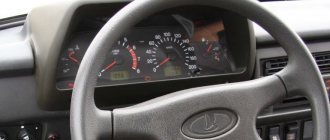
Shield Niva 21213
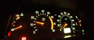
A transitional link between the classical and modern systems. The dial indicators and indicators are similar to the dashboard of the VAZ 2105, which many car enthusiasts do not like, and they want to change it.
Which panel is suitable for Niva 21213
Users often install panels from a VAZ 2114 or 2110 car. A minimum number of alterations and modifications will be required here. Contact groups and wiring terminals are reinstalled under the required pins. Refinement of plastic and seat will be required.
Pinout of the instrument panel VAZ 2121
| Plug no. | Plug address | |
| Block X1 (red or orange) | Block X2 (white or other color except red/orange) | |
| 1. | ─ | ─ |
| 2. | To terminal “15” of the ignition switch | High beam warning lamp |
| 3. | Low voltage tachometer input | To the gab. lighting (control lamp) |
| 4. | To the instrument lighting control | To terminal “15” of the ignition switch |
| 5. | High voltage tachometer input | To hazard warning switch |
| 6. | Housing (weight) | To output "D" of the generator |
| 7. | To terminal “50” of the ignition switch (starter) | ─ |
| 8. | To the parking brake warning lamp switch | Fog lamp warning lamp |
| 9. | ─ | Rear window heating indicator lamp |
| 10. | To the fuel reserve lamp | Check Engine |
| 11. | To differential lock sensor | To fuel level sensor |
| 12. | To emergency oil pressure sensor | Check Engine |
| 13. | To brake fluid level sensor | To coolant temperature sensor |
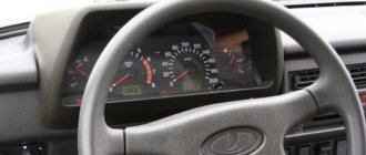
Shield Niva 21214
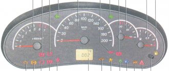
In the version where the injector is installed, the manufacturer installs a relatively modern device with a small display. The partially digitized version is easier to read and has a new indicator - a seat belt light.
Which panel is suitable for Niva 21214
On this version, users rarely change the device. The native panel is informative and only overexposure may be required here. If the driver decides to make a replacement, he needs to choose from a Lada tenth series car.
Video “Replacing tidy at home”
The main nuances and features of replacing the control panel on the Niva are shown in the video below (author - Vladimir Kucher).
Loading …
Read news about the new Niva
- Instrument panel Niva Chevrolet designations. Improving the Chevrolet Niva dashboard
- Diagram and pinout of the Niva 4x4 instrument panel (VAZ 2121, 2131) » Lada.Online
- Instrument cluster Chevrolet Niva tuning
- The instrument panel and its replacement on a Chevrolet Niva
- FROST car air conditioners // Online store // Prices // Air conditioners for cars Lada VAZ, VolksWagen Polo, Daewoo Matiz
- Installing fog lights on a Chevrolet Niva
- Installation and repair of the VAZ 2121 Niva transfer case
- Tuning for VAZ Niva 4×4 (LADA Niva) buy with delivery throughout the Russian Federation
The device on the Niva failed - the reason
For most classic versions, problems exist.
- The corresponding fuse has blown. This is usually insert F2.
- There are problems with the wiring. Such problems are not uncommon in classic car models. Here you should check the wires for damage to the insulation, loosening, oxidation of contact groups, breaks.
- Damage to the device. Here you should check the device circuit for breakdowns and burns.
If we are talking about modern modifications with an ECU, it is easier to find the problem using computer diagnostics. The BC standard errors will accurately indicate the location of the fault.
Niva instrument panel does not light up
The backlight of the shield is checked in the same way. If the panel periodically blinks or only some of the indicators go off, check the wiring. This is where the contact groups are usually oxidized. It is also possible that the integrity of the insulation may be compromised and individual light bulbs may burn out. If the backlight goes out completely, check the lighting fuse.
Possibilities of the daily mileage reset button
The mileage reset button on the Niva Chevrolet and Niva Travel has a lot of useful functions:
- Setting the time.
- View the outside temperature and on-board voltage.
- Mileage reset.
- Starting the self-diagnosis system
Each possibility should be considered separately.
Setting the time
Turn the barrel switch fully clockwise to set the clock. Shifts will take place one hour at a time. To adjust the minutes, you need to turn the button counterclockwise. The time will be saved independently and will be reset only after the battery is disconnected or after the instrument panel on the Niva is rebooted.
View outside temperature
To display the outside temperature on the left display, you need to briefly press the button and release. Pressing the button again will display the on-board network voltage on the display, if provided for by the version of the panel.
Mileage reset
To reset the mileage on your Niva Travel, press the button and hold until “0.0” appears on the bottom line.
Self-diagnosis system
The instrument panel on the Niva Chevrolet is being diagnosed. To do this do the following:
- With the ignition off, press and hold the mileage reset button.
- Turn on the ignition.
- You can release the button, and the arrows on the dashboard will begin to move and all the lights will light up. This way the panel checks the functionality of all elements.
- Pressing the button again will display the software version.
- Another press will show engine error codes.
Despite the possibility of engine diagnostics, its readings are not always correct and therefore do not inspire confidence. For diagnostics, you should use appropriate software and devices.