Don’t ask me anything, I wrote everything I know.
You can copy this article to your blog, then notify me so that I can delete this entry.
First type of devices:
Kalinas and Prioras without can tires.
On the VAZ-1118 (Kalina) from 2004 to 2011, the device was installed 1118-3801010
All these devices have a 32-pin connector. You can, for example, install a Priorovskaya tidy instead of a Kalinovskaya one, but it is advisable to select the desired model (1118 or 2170).
Instead of such a tidy, you can install an expensive tidy with navigation 1118-3801010-50 for Kalina and 2112 with Europanel or 2170-3801010-50 s for Prior produced before July 2012 (without CAN bus). And they additionally need a GPS antenna and a wiper switch with a joystick (they are described below).
Addition from Shurik5891
On the first releases of 1118 devices, there are no LEDs for ABS, ESD, or seat belts.
Addition from Shandys
On Kalina1 2013
with e-gas and cable drive gearbox there is a tidy 11180-3801010-20 vdo _____________________________________ Second type of
Grant devices of the 1st generation
Granta appeared in 2011
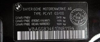
From a smart book: “The electronic engine control system of the LADA GRANTA car implements a data exchange interface between the ECM, instrument cluster and diagnostic device via the CAN bus. The CAN bus is a two-wire line: - CAN L low level line (contact “X2/D2” of the ECM - contact “7” of the instrument cluster - contact “14” of the diagnostic block); - CAN H high level line (contact “X2/F1” of the ECM – contact “8” of the instrument cluster – contact “6” of the diagnostic block). The immobilizer is integrated into the instrument cluster." Pinout of devices 2190
: 1 - To the emergency oil pressure sensor, 2 - To the parking brake switch, 3 - Service. Panel diagnostics, 4 — To the exterior lighting switch, 5 — To the right turn signal switch, 6 — To the left turn signal switch, 7 — CAN-L, 8 — CAN-H, 9 — To the seat belt sensor, 10 — “RESET” key » on the steering column switch, 11 - To the brake fluid level sensor, 12 - To the high beam headlights, 13 - To the low beam headlights, 14 - To the rear fog lamp, 15 - To the front fog lamps, 16 - Immobilizer antenna input (b) , 17 — “Ground” panel, 18 — Immobilizer antenna input (a), 19 — To terminal “30,” 20 — To electric power steering, 21 — To terminal “15,” 22 — To door sensor, 23 — MK key “ forward", 24 - MK key "back", 25 - To the outside temperature sensor, 26 - To the fuel level sensor. Instrument clusters are interchangeable.
Pinout provided by fellow teemest
The connector for these devices is 26-pin.
Some devices have sound for turn signals and/or hazard lights, some do not. This is normal and is not a malfunction. Instead of a temperature indicator, there was only a light bulb, the lighting of which indicated overheating. On June 16, 2014, they began installing the device with firmware 092, and in the window it was possible to select engine temperature readings. On cars with the standard configuration, there is no outside temperature sensor. If the device has firmware 090, you can take sensor 2115-3828210, one contact to the body, the second to contact 25 of the devices, and the function of displaying the outside temperature will work. Devices may also differ in the presence/absence of an indicator for front fog lights, an indicator for an automatic transmission, etc. And there are these same devices with navigation.
A detailed article on flashing such devices is here www.drive2.ru/l/6010764/
The third type of devices
Priora 1 with can-bus.
Since July 2012, Priora also began installing devices with a CAN bus. For example, 2170-3801010-30 Addition from turbomotor412
Pinout of CAN panel Priora 1st generation 2170-3801010-30. 1) To the electric power steering, 2) Reserve, 3) Reserve, 4) To the parking brake switch, 5) To the immobilizer control unit (electrical package), 6) Reserve, 7) To the light control module (light on indicator), To the switch turn signal (right side), 9) To the turn switch (left side), 10) CAN_L, 11) CAN_H, 12) Immobilizer antenna (not engaged), 13) Immobilizer antenna (not engaged), 14) To the steering column switch (" button Reset"), 15) To the brake fluid level sensor, 16) Reserve, 17) To the high beam switch, 18) To the light control module (light dimmer), 19) Housing, 20) Terminal “30” of the battery, 21) Terminal “15” of the ignition switch, 22) Reserve, 23) To the steering column switch (down button), 24) To the steering column switch (up button), 25) To the outside temperature sensor, 26) To the outside temperature sensor, 27) To the fuel level sensor, 28) Reserve, 29) Reserve, 30) Reserve, 31) Service. Diagnostics of instrument cluster during production, 32) Reserve
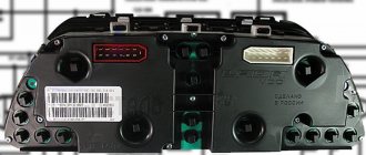
Standard instrument panel - article number and price
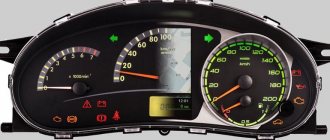
The original car tidy exists in three types.
- the first is an option for a pre-restyling car;
- the second panel is for a restyled car;
- and the third is the “Lux” option for the restyled one, which has become faintly similar to all previous torpedoes.
Each of them contains standard elements such as a tachometer, so their functionality does not decrease. . Who wants to do tuning of the instrument panel, this option is for them.
Priora first generation
The instrument cluster for the first generation Lada Priora received catalog number 2170-3801010. Cost – about 6,000 rubles. Everything is standard with it - from left to right there are four arc scales with red arrows: odometer, speedometer, coolant temperature, fuel level. Below the speedometer there is a small on-board computer display, and above the arches are all the indicators, including the direction indicators.
Priora 2
For the Priora “Lux” variation there are two more “subtypes” - with or without a CAN bus. Different subtypes were made so that the panel could be connected to any car. Catalog number – 2170-3801010-50 without tire, 2170-3801010-60 with tire. It is distinctive in that it contains an elongated display with a screen that can highlight the navigator.
The catalog number of the combination for the “Norma” assembly is 21720-03801010-20. Cost – 6,500 rubles. Like the “Lux” version, it received a brighter speedometer and odometer, and the coolant temperature along with the fuel level indicator is hidden at the bottom of the speedometer and odometer. The base will not create a route on the display, but will show all the information in color.
Do-it-yourself dashboard tuning on Priora
Torpedo of a Lada Priora car
The dashboard on the Lada Priora has improved characteristics compared to previous models of the domestic automobile industry. When creating it, “soft look” class plastic was used, which looks like good leather and is scratch-resistant. The same material, in addition to the dashboard, is on the upper trims of the door trims. The new Lada instrument panel in the “luxury” configuration may have a number of parts decorated with black varnish.
The panel on the Priora has a large display with touch control, which displays auxiliary and external information, in particular: the navigation screen, settings from the multimedia system, parameters from the trip computer, etc. Experts note that the instrument panel computer is maximally adapted for Russian users, i.e. - information is transmitted in Russian.
Icons on the factory dashboard
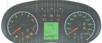
All indicators should light up like a Christmas tree for three seconds when the engine starts. If some icon remains, it means the system is signaling a breakdown. To make it easier to understand all the indicators, here is a schematic picture:
1,5,9,10 are already known scales that display the main parameters that can change. 19 – on-board computer display. Further:
- 2 – Icon indicating the operation of the braking system.
- 3 – Battery condition. If the light remains on, the battery is discharged or the charge level is too low.
- 4.7 – Doublers for direction indicators (“turn signals”).
- 6 – Oil level (indicates low level).
- 8 – Handbrake. Lights yellow when the lever is tightened.
- 11 – “Gasoline light bulb.” Lights up when there are only 10 liters left.
- 12 – Button for switching on-board computer modes.
- 13 – “Emergency”.
- 14 – Electric power steering (indicates a breakdown).
- 15 – High beam on.
- 16 – Side lights/low beam.
- 17 – Airbag condition (malfunction).
- 18 – Immobilizer (if you hear a beep and the icon itself blinks, the immobilizer is faulty).
- 20 – Seat belts not fastened.
- 21 – Unsatisfactory condition of the service brake system.
- 22 – Disabling the airbag.
- 23 – ABS malfunction.
- 24 – “Check”, “Check Engine” - engine failure.
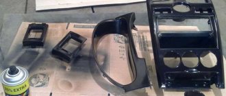
Do-it-yourself tuning and dismantling of the center console
Dismantling the center console on the Lada Priora is quite simple, but has a number of secrets. First, you need to remove the “Open” cover and unscrew the two screws underneath it. Then remove the ashtray and also unscrew a couple of screws under it. Next, remove the tape recorder and take out the frame, under which again there will be two screws that must be unscrewed. The cover needs to be pulled towards you in order to remove the central nozzles from the stove at the top (overcoming some resistance). After the top disconnection, you need to stick your hand in and remove the connectors from the heating, clock, emergency lights, control system. The center console can now be completely removed.
Car interior tuning
The Lada Priora, which came off the assembly line, has fairly light colors in the interior, which can be made darker by painting the center console, door handles, and replacing the upholstery. For painting we will need white spirit, varnish, acetone, primer for metal and plastic, and spray paint. The center console is degreased, primed in a couple of layers with drying between them, painted in 2-3 layers (also with intermediate drying), and varnished.
The situation is much worse if the instrument panel in the Priora is faulty and requires repair. In this case, pinout is needed, i.e., matching the contacts and wires to a particular device. The description of the combinations for the shield states that contacts 2,3,5,6,8,9,16, 17,22, 28-30 are reserve,
- while contact No. 1 goes to the power steering, No. 4 goes to the parking brake switch (both negative),
- No. 7 - to the lighting module (plus),
- No. 8 - on CAN_H,
- No. 9 - on CAN_L,
- No. 12-13 - immobilizer antenna inputs (a and b),
- No. 14 - to the “Reset” switch,
- No. 15 - to the brake fluid level sensor (minus),
- No. 18 - to the backlight adjustment module,
- No. 20 - to the terminal on the battery “30” (plus),
- No. 21 - to the ignition terminal “15” (plus),
- No. 23 - to the “menu down” key on the steering column switch, No. 24 - to the “up right” key on the steering column switch (both negative),
- No. 25-26 - to external temperature sensors (minus and plus, respectively),
- No. 27 - to the fuel level sensor,
- No. 31 - to the diagnosis of the instrument cluster.
Possible faults
The instrument cluster does not always tell the truth, and sometimes its readings can mislead the driver - they may seem absurd. For each common malfunction, a brief commentary will be given on the possibility of eliminating them:
- The fault lamp does not light up (check the lamp);
- the lamp is on - check the sensor, reset the error via the diagnostic connector.
If none of the above measures help resolve the problem, carefully inspect the wiring - damage to it may cause the light bulb to activate or deactivate.
Required
The Itelma instrument panel with navigation can be of two types (externally they are no different):
- 2170-3801010-50 without CAN bus;
- 2170-3801010-60 from CAN bus.
They are not interchangeable, so before purchasing, you should determine whether your vehicle uses a CAN bus or not.
- until 06.2012, cars were produced without a CAN bus;
- remove the instrument cluster and look at the article number or at the block with wires (see pinout of connectors below).
For Kalina (VAZ 1117, 1118, 1119) - all cars without a CAN bus.
- Right steering column switch with joystick (catalog number: 1118-3709340-20);
- Antenna (for roof installation): 1118-7903074.
New-style Priora instrument panel steering column switch with joystick Kalina/Priora/Granta antenna for the Priora instrument panel
You can also buy ready-made kits (device + antenna + switch):
- for Lada Priora - 2170-3801010-55;
- for Lada Kalina 1 - 1118-3801010-55.
old-style Priora dashboard
New-style Priora instrument panel
Replacement of the old instrument panel without CAN with a dashboard with navigation without CAN (2170-3801010-50) is carried out without modifications. We remove the old panel and install a new one in its place, insert the connector with wires, connect the antenna (we fix it on the roof) and, if necessary, change the right steering column switch.
If the old instrument cluster without navigation, but with CAN, and instead of it it is planned to install a new dashboard with navigation with CAN (2170-3801010-60), then you need to rearrange contacts 10-11 to 28-29 (if after connecting it still does not work, change 28 and 29 places).
Pinout of the instrument panel of a Priora car
The panel pinout looks quite complicated, but there is a more simplified diagram that will help you figure out the wires connected inside:
- EUR
- "emergency light"
- Engine oil
- Handbrake
- Immobilizer
- Airbags
- Headlights and dimensions
- Right turn signal
- Left turn signal
- Electronic control unit
- Pad wear sensor
- Seat belts (closing sensor)
- ABS
- Reset button
- Brake system, brake fluid
- ABS
- High beam headlights
- Torpedo shield lighting
- "Weight"
- Thirtieth terminal
- Fifteenth terminal
- Fuel consumption
- Forward key
- Back key
- Ambient temperature sensor (minus)
- Ambient temperature sensor (plus)
- Fuel level
- Speed sensors
- Coolant temperature
- Odometer
- Diagnostics of the shield (service)
- Generator regulator
Circuit breakers
LADA PRIORA 21723
Fuse box of Lada Priora under the hood
F1 (green) 30 Electronic engine management system F2 (blue) 60 power package control unit, engine fan, heated rear window, ignition switch relief relay F3 (blue) 60 cooling fan power supply circuit, horn, alarm, ignition switch, combination devices, interior lighting, brake light, cigarette lighter F4 (blue) 60 Generator Priors F5 (red) 50 Electromechanical power steering F6 (blue) 60 Generator
Fuse box of Lada Priora in the cabin
F1 (blue) 15 Main relay and starter interlock circuit F2 (brown) 7.5 Controller power circuit F3 (blue) 15 Electric fuel pump fuse K1 - Ignition relay K2 - Electric fuel pump relay
Lada Priora fuse box under the instrument panel
F1 25 Electric radiator fan of the cooling system F2 25 Heated rear window Priors F3 10 High beam right F4 10 High beam left F5 10 Sound signal F6 7.5 Low beam (left) F7 7.5 Low beam (right) F8 10 Alarm signal F9 25 Heater Priors F10) 7.5 Interior lighting, instrument cluster, brake light F11 20 Windshield wiper F12 10 Terminal 15 devices F13 15 Cigarette lighter F14 5 Left side light, license plate light, trunk light F15 5 Right side light F16 10 Terminal 15 ABS F17 10 Fog light (PTF) left F18 10 Fog light (PTF) right F19 15 Heated seats F31 or F27 30 Electrical package control unit
How to enable self-diagnosis of the instrument panel
Using the panel you can “dig into the brains” of the Priora:
- Hold the button under the fuel gauge and turn on the ignition. The display should indicate the start of the test.
- Press the button again. The display should show the operating system version.
- Click again. The system should show error codes:
- (2) – High voltage level;
- (3) – DT malfunction;
- (4) – DTOZH malfunction;
- (5) – DTV malfunction;
- (6) – Motor overheating;
- (7) – Low oil level;
- (8) – Malfunction of the brake system;
- (9) – Battery discharge;
- E – Brain error, EEPROM.
- If necessary, reset the error: hold the button for three seconds.
- Release the button. Click again. All indicators should light up.
- Leave all the buttons. After 30 seconds, the self-test will automatically complete.
The dashboard contains the following parts, without which the car would not function:
- external lighting controller;
- switch for turning and lighting headlights;
- signal regulator;
- instrument cluster;
- wiper regulator.
The device also has an ignition switch consisting of three positions. Secondary components include controls for the heater, alarm and interior cooling.
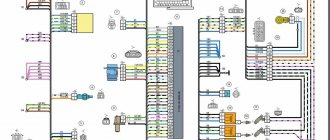
General diagram of electrical equipment of Kalina
On the electrical circuit of the Lada Kalina model, the pinout of connectors is carried out in several stages. According to the factory drawings, the general position of the elements is initially revealed, then each node is deciphered separately.
- Right front headlight assembly.
- Sensor indicating the position of the hood lock.
- Powering the horn.
- Starter terminal block.
- Battery power cables.
- Generator working unit.
- Voltage supply terminal for the wiper drive.
- Left head optics contact block.
- Right door lift chip.
- Likewise for the glass lift gearbox.
- Output to driver's door speaker.
- Driver's door lock drive.
- Windshield washer reservoir motor.
- Overboard temperature meter sensor output.
- Standard ECM connection connector.
- Same as 12 for the front passenger.
- Indicator of the remaining brake fluid in the expansion tank of the system.
- Same as 11 for the front passenger.
- The front passenger door power window switch, located in the driver's control unit.
- Driver's door window lift key.
- Lock button.
- Power supply for the lift gearbox for the front passenger door.
- Input of the mounting assembly.
- Anti-theft control unit.
- Likewise for signaling.
- Pinout on the dashboard.
- Right turn.
- Glove compartment lighting.
- Glove box light switch.
- Stop key switch.
- Anti-theft ignition switch terminal.
- Headlight design.
- Supply current to the steering column lever connector.
- Left turn signal.
- Right rear speaker block.
- Rear right door electric lock drive.
- Window window heating unit.
- Reverse blocking.
- Hazard breaker.
- Adjusting the stove fan.
- Auxiliary resistor for the stove.
- Stove motor.
- Power supply for rear left speaker.
- Rear left door lock terminal.
- Power supply for fuel pump and float.
- White reverse lamp switch.
- Stop button.
- Cigarette lighter power supply.
- ZX blocking – solenoid power supply.
- Chips for a tape recorder or speaker system.
- Illumination of used ventilation and stove.
- Supplying voltage and signals to the EUR.
- Interior lighting lamps.
- Rear right lampshade.
- Power to the trunk lid lock.
- Cargo compartment lighting drive.
- State license plate illumination.
- Auxiliary stop lamp.
- Directly heated windshield.
- Cargo compartment illumination lamp.
- Left stern light.
The following is the pinout of the first generation Kalina wires for each section individually. This was done due to the increased complexity of the main circuit, where all elements of the on-board circuits are indicated at once. An inexperienced user will not be able to navigate the generalized instructions.
When is pinout required (device chips) and how to do it
All car parts fail sooner or later. There are times when they need to not only be repaired, but replaced. The instrument panel may also break, causing it to be removed and a new one installed in its place. This work is easy to do with your own hands if you have at least the slightest knowledge of mechanics. If you are well versed in your Priora (sedan), then you need to perform the pinout in this way:
- First, the dial hands are removed using a regular knife.
- Next, the gasket in the speedometer is scraped out to replace the backlight.
- If there is no need to change the sensors, you can simply remove them and clean them.
Very often, motorists cover the panel with a special LED strip to achieve even lighting.
You can also use CMD diodes, which can be easily fused into glass with a soldering iron. To do this, you need to disassemble the dial and solder diodes directly under the base of the hands. If you understand the purpose of all the contacts, and also know the purpose of a particular connector on the panel, then you can easily do the pinout yourself. The main thing is to carry out everything strictly according to the instructions so that the connection is successful and the panel continues to function efficiently. If you know which is better to install a tidy: with a canbus or a regular one, then it’s better to ask professionals who understand this. If you have no experience in such work, and you do not understand the purpose of certain wires, then the technical service will help you improve the operation of the instrument panel. Of course, you will have to pay for this, but you will not waste your time, and the work will be done efficiently.
Prevention
As a measure to prevent breakdowns, experienced specialists recommend periodically performing maintenance on electrical circuits. This requires a complete review of all wires and disconnectors twice a year for damage to the braiding and oxidation of copper contacts. Damaged parts or loose joints must be replaced with new ones.
Also, advice from “experienced” motorists speaks of the rationality of treating parts with special dielectric oil - this prevents air and moisture from entering sensitive areas and significantly increases the service life of devices.
Lada Priora Hatchback Turbo › Logbook › Installing a daytime running lamp controller
Dashboard pinout
Connecting VDO on a Priora car
1 Pink-white To the electric power steering 2 Blue-white To the hazard warning light 3 Gray-blue To the emergency oil pressure sensor 4 Brown-blue To the parking brake switch 5 Yellow-blue To the control unit immobilizer 6 Black To the airbag control unit 7 Yellow To the exterior lighting switch 8 Blue To the right turn signal switch 9 Blue with black To the left turn signal switch 10 White-blue To the ECU 11. To the brake pad wear sensor 12. To the seat belt sensor 13 Black To the traction control control unit 14 Red-blue “RESET” key on the steering column switch 15 Pink-blue To the brake fluid level sensor 16 Black To ABS 17 Green To the headlight high beam switch 18 White To the instrument cluster light control 19 Brown Panel weight 20 White -red Terminal “30” 21 Orange Terminal “15” 22 Yellow-red To fuel consumption sensor 23 Orange-white MK “forward” key 24 White-black MK “back” key 25 Black-white Outside temperature sensor (-) 26 Yellow -green Outside temperature sensor (+) 27 Pink Fuel level sensor 28 Gray Speed sensor 29 Green-white Coolant temperature sensor 30 Brown-red Tachometer (low voltage) 31. Service. Panel diagnostics. 32 Brown-white Terminal “L” of the generator relay regulator
Here we connect: 1) Speed control, connect the white wire to the gray wire (pin 28 of the dashboard connector) 2) Ignition, connect the yellow wire to the orange (21 pin of the dashboard connector) 3) Dimensions connect the blue wire to the yellow (pin 7 of the dashboard connector)
Next we are interested in the mounting block, on the left under the panel, namely K7 - the relay for the high-beam headlights.
A mass is attached above the mounting block with a bolt.
We unscrew the screw from the bottom and take out the mounting block from the panel; we need the relay on the bottom left.
1) Connect the red constant plus wire to the pink wire going to the high beam relay. 2) The green wire in our case to the white-green wire going directly through the fuses to the lamps
What we end up with: 1) When autostarting, the lamps do not light up. 2) The lamps light up smoothly when you start moving. 3) When parked for a long time, the headlights first dim by 50%, then turn off. 4) When the headlights are turned on, the lighting goes into normal mode and the DRL turns off.
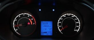
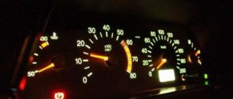
The instrument panel glows mysteriously under the steering wheel of the Priora. Speedometer, tachometer, various gauges and indicators. It seems that this is an airplane cockpit, and not an ordinary civilian car.
How much has been said about the fact that the modern Priora is a machine subordinate to a computer, an electronic control unit (ECU). But what about such a thin element as the instrument panel? Did he escape this fate? No. And one might even say that this is the most computerized part of the machine.
Pros and cons of CAN bus
Automotive electronics specialists, speaking in favor of using a CAN interface, note the following advantages:
- simple data exchange channel;
- information transfer speed;
- wide compatibility with operating and diagnostic devices;
- a simpler car alarm installation scheme;
- multi-level monitoring and control of interfaces;
- automatic distribution of transmission speed with priority in favor of the main systems and nodes.
But the CAN bus also has functional disadvantages:
- with an increased information load on the channel, the response time increases, which is especially typical for the operation of cars “stuffed” with electronic devices;
- Due to the use of a higher-level protocol, standardization problems occur.
Development of a sniffer and study of the CAN bus protocol
After I have access to listen to the CAN bus, I need to decipher who is transmitting what to whom. The CAN packet format is shown in the figure.
All utilities from the can-utils set can parse CAN packets themselves and provide only useful information, namely:
The data is transmitted unencrypted, which made it easier to learn the protocol. On the Raspberry Pi I wrote a small server that redirects data from candump to TCP/IP in order to parse the data stream on the computer and display it beautifully. For macOS I wrote a simple application that adds a cell to the table for each device address and in this cell I can already see what data is changing.
I press the power window button, I found a cell in which the data changes, then I determined which commands correspond to pressing down, pressing up, holding up, holding down.
You can check that the command works by sending from the terminal, for example, the command to raise the left glass up:
cansend can0 181#0200 Commands that transmit devices via the CAN bus in VAG cars (Skoda Octavia 2011), obtained by reverse engineering: // Front Left Glass Up 181#0200 // Front Left Glass Down 181#0800 // Front Right Glass Up 181#2000 // Front Right Glass Down 181#8000 // Back Left Glass Up 181#0002 // Back Left Glass Down 181#0008 // Back Right Glass Up 181#0020 // Back Right Glass Down 181#0080 // Central Lock Open 291#09AA020000 // Central Lock Close 291#0955040000 // Update Light status of central lock (When you send a command to open/close the lock, the LED on the lock control button does not change state so that it shows the real status of the central lock, you need to send an update command) 291#0900000000 I was too lazy to study all the other devices, so in this list, only what was interesting to me.
If you know how to disassemble the panel, you can completely change the backlight
Tuning the instrument panel on a Lada Priora car usually does not end there, because car enthusiasts want to get more uniform lighting, which requires replacing the light bulbs. To do this, pieces of LED strip are glued around the perimeter of the panel, which need to be connected using thin wires and connected to the contacts of the standard backlight (plus to plus, minus to minus).
Replacing light bulbs is often accompanied by replacing the green filter in the display; for this purpose, you need to disassemble it and install a filter of a different color or leave the backlight on white.
Tuning of devices on Priora can be effectively complemented by a new way of illuminating the arrows. For this, red CMD diodes are used, three each for the tachometer and speedometer and two each for the engine temperature and fuel level scales. They need to be melted into the plexiglass from the instrument panel (you can use a soldering iron) under the base of the arrows, and resistances must be soldered on the reverse side (130 Ohms for three CMDs and 300 Ohms for two CMDs).
Tuning the center console often comes down to the fact that the driver seeks to eliminate unpleasant creaking. To do this, you need to remove the console lining, cover the edges of the lining, the place of contact with the panel, and the edges of the lining of the area under and above the stove control with madeline or polyurethane foam insulation. It will not be superfluous to tape the pocket, because it will become a little heavier and will not rattle.
What is a CAN bus?
This is one of the many electronic devices in the car. It is entrusted with the task of combining various sensors and processors into a single system with synchronization. The bus ensures the collection and exchange of information that is necessary to correct the operation of vehicle systems and components. CAN is short for Controller Area Network. Therefore, the bus is a kind of “road” for transmitting information from the controller to devices and vice versa. This standard was developed and implemented more than three decades ago. Today it is used not only in cars, but also in industry, including in smart homes.