The modern Lada Granta model is in demand among domestic car enthusiasts due to its optimal cost and sufficient reliability. Good strength and low cost of consumables further stimulate demand among the population. The downside of the car is frequent breakdowns in the electrical part. On-board systems often fail. The website contains a detailed electrical diagram of Grant with explanations and interpretation.
Full pinout of Grant, divided into several sections for a more detailed image and easier perception. Present here.
- The engine compartment - the harness combines all the elements of the wires located in the area of the engine and main instruments.
- Salon module. The design is further divided into zones that provide for the connection of individual parts of the wiring.
- Instrument panel module. All elements coming from sensors, instruments and indicators are concentrated here.
- The rear harness is located in the rear of the car and is responsible for supplying power to the lighting, lock and instrument modules.
All the given transcripts are taken from the manufacturer’s official instructions and fully comply with the factory designations and the standard version diagram.
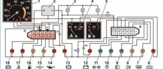
Grant's electrical circuit responsible for the engine compartment
Here are the main parts of the Lada Granta wiring, which are responsible for the normal operation of the power plant:
- 1 – power supply to the headlight, front right;
- 2 – power supply for windshield washers;
- 3 – voltage to the left side of the head optics;
- 5 – on-board power supply;
- 6 – head fuse block;
- 7 – generator;
- 8 – horn;
- 9-11 – terminal blocks to the dashboard;
- 12 – contact pair of rear headlights;
- 13 – main radiator fan drive.
Power fuses
The power fuse box is located under the hood and is located between the battery, strut support and coolant reservoir. Looks like a vertically mounted box. By removing the top cover, access to the power fuses appears.
F1 (50 A) - electric power steering. If the steering wheel turns hard, also check fuse F32.
F2 (30 A) - heater fan
F3 (60 A) - generator. If the battery discharges quickly or the discharge lamp is on, check this fuse, as well as the operation of the generator itself and its brush.
F4 (60 A) - generator
F5 (30 A) - low beam headlights. Also check relay K9 and fuses F12, F13.
When troubleshooting any electrical problems, use caution. Replace fuses and relays only with the engine off and the ignition off.
If your fleet contains not only Grants, you can also read about Kalina fuses and relays.
I’ve already written more than once, the dashboard
, i.e. it sometimes lights up for a couple of seconds (once a month) and goes out, the problem has been around for a long time, I thought, I recently transferred it from another car, one of them doesn’t light up, I changed the fuse, I changed the cigarette lighter, I changed the relay, has anyone encountered this? It’s clear that it’s easier to go to an auto electrician))) But suddenly someone has already encountered this. Thank you))
Lada Granta diagram - ignition part
- 1 – indicator of lubricant pressure in the crankcase of the power plant;
- 2 – generator connector;
- 3 – power supply to the fuel mixture supply valve;
- 4 – cooling system thermometer;
- 5 – sending a signal to the dashboard;
- 6 – adsorber purge;
- 7 – speedometer;
- 8 – mass air flow sensor;
- 9 – DPKV;
- 10 – DC in front of the catalyst;
- 11 – control pulse device;
- 12 – oxygen concentration sensor in exhaust gases;
- 13/14 – coil and spark plugs, respectively;
- 15 – injector drivers;
- 16 – ignition contact group;
- 17 – detonation measurement sensor.
An effective way to adjust the backlight
The problem with the first modifications of the Lada Vesta is insufficient lighting of the dashboard. In sunny weather, the driver cannot see the readings of sensors and instruments. Excessive distraction on the “visor” provoked accidents, crashes, and collisions with oncoming traffic.
In order to eliminate the defect, engineers developed and made publicly available on-board computer firmware with an increased brightness coefficient. However, the program code did not always work correctly, and malfunctions occurred from time to time.
Self-taught people worked together with the official VAZ developers and came up with a much better method - installing a 2-channel PWM controller.
The cost of a set of equipment is from 650 rubles in online catalogues, perhaps it will be cheaper in the car market. There is no catalog article, look for the production name: “KIT, PWM power regulator set, 12-50V 30A, 20kHz.”
Grant instrument pinout - dashboard diagram
This part is the most difficult. The large number of pins and the miniature size of the terminals greatly complicates the search for the required group:
- 1/2 – connecting blocks for the front electrical harness;
- 3/4 – similar for the feed harness;
- 5 – lighting control unit;
- 6 – ignition switch module;
- 7 – on-board computer;
- 8 – lever for switching the position of the wipers;
- 9 – tidy;
- 10 – control of emergency modes;
- 11 – cargo compartment lid lock;
- 12 – diagnostic connector;
- 13 – block for the air intake drive;
- 14 – button to turn off the heated rear windshield;
- 15 – emergency contact;
- 16 – brake light switch;
- 17/18 – contact group – output to radio equipment (radio tape recorder);
- 19 – rotating equipment module;
- 20/41 – driver/passenger airbag drive;
- 21 – horn power supply;
- 22 – mounting block group;
- 24 – cigarette lighter group;
- 25 – backlight for stove control;
- 26 – interior lamp;
- 27 – contact group of the ignition switch;
- 28 – controller;
- 29 – incoming connector to the rear of the on-board network;
- 30 – electronic part of the gas pedal;
- 31 – additional resistor;
- 32 – stove motor;
- 33 – heater switch block;
- 34 – door lock module;
- 35/36 – cooling system head fan relay;
- 37 – compressor relay wiring;
- 38 – additional relay or reverse indication coil;
- 39 – air conditioner switch button;
- 40 – automatic transmission drive;
- 42 – evaporator thermometer;
- 43 – output to the rear wiring harness.
How to change the color of the instrument cluster illumination
1. Use SMD of the desired color. For example, use white LEDs to illuminate one part of the panel, and blue LEDs for the other.
2. Use a light filter (electrical tape or film of different colors) together with white LEDs. We stick it on the desired area, as a result of which we get the illumination of the desired color. To change the color, you do not need to use a soldering iron, just disassemble the instrument panel and stick a film of a different color.
It is worth noting that the hands have an orange coating. To change the illumination of the hands, wipe off the varnish with nail polish remover and, if necessary, apply a new varnish of a suitable color. Another option is to use LEDs for the arrows of the desired color.
You can change the backlight of the screen (display) not only by replacing its LEDs, but also by turning the film over. First, we tear off the film from the display, clean the remaining adhesive with a solvent and glue the film on the back side. This results in an inversion of the panel display:
3. Use RGB-SMD LEDs. If you want to change the backlight color at once. In this case, you will have to additionally output switching control.
Grant ECU pinout
The Lada Granta uses two types of electronic engine control units. Fundamentally, the systems differ slightly, which excludes the possibility of their interchangeability.
| Contact | 11183-1411020-51/52 | 11186-1411020-21/22 |
| A1 | DPKV | |
| A2 | Not involved | |
| A3 | Entering the first knock sensor | |
| A4 | Not used | |
| IN 1 | DPKV | |
| AT 2 | Not involved | |
| AT 3 | Input of the second knock sensor | |
| AT 4 | Main relay output | Not used |
| C1 | Empty | |
| C2 | DTV | |
| C3 | Mass air flow sensor | |
| C4 | UDC | |
| D1 | DDC weight | |
| D2 | Empty | |
| D3 | DTOZH | |
| D4 | Not applicable | |
| E1 | Zeroing the TPS | |
| E2 | Empty | CAN L |
| E3 | Empty | CAN H |
| E4 | Canister purge valve output | |
| F1 | Body from DTV | |
| F2 | Speedometer input | |
| F3 | Not applicable | DFM |
| F4/G4/H4/J4 | Output from injector No. 1/2/3/4 | |
| G1 | Antifreeze temperature sensor ground | |
| G2/G3 | Not used | |
| H1 | On-board electronics grounding | |
| H2 | UDC | |
| H3 | Not involved | Battery charge indicator output |
| J1 | Terminal No. 15 from the ignition switch | empty |
| J2 | Entrance No. 2 TPS | |
| J3 | DDC | |
| K1 | Supplying voltage to the TPS | |
| K2 | Entrance No. 1 TPS | |
| K3 | UDC | |
| K4 | DDK heater power connector | |
| L1/M1 | Leads to the ignition coil ¼ and 2/3 cylinders respectively | |
| L2/M2; L3/M3 | Not involved | |
| L4/M4 | Throttle actuator pin 5/6 | |
Grant relay diagram
Relay location in the main mounting block located in the engine compartment:
- 1 – drive of the cooler of the cooling system;
- 2 – central locking protection;
- 3 – secondary starter relay;
- 4 – additional part of the relay;
- 5 – turn signal and emergency signal breaker relay;
- 6 – wiper drive protection;
- 7/9 – insertion of high/low headlight modes;
- 8 – horn protection element;
- 10 – heated aft windshield;
- 11 – main relay block;
- 12 – fuel pump relay.
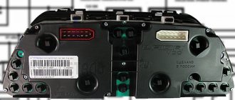
Detailed diagram of the VAZ Grant (dashboard)
The vehicle is supplied to the market with a 32-pin instrument panel as standard. The standard pinout of the Grant shield has only 26 pins involved. Residual connectors are provided for the possibility of adding equipment or custom modifications:
- 1 – to the low oil pressure sensor in the engine crankcase;
- 2 – to the handbrake indication switch;
- 3 – intended for service needs when diagnosing the instrument panel;
- 4 – to external lighting switches;
- 5/6 – similar for right and left turn signals, respectively;
- 7/8 – CAN L/H;
- 9 – indication of seat belt position;
- 10 – contact of the Reset button of the steering column lever;
- 11 – response of the brake fluid reservoir sensor;
- 12/13 – on the head optics, high/low beam position;
- 14/15 – foglight terminals front/rear, respectively;
- 16/18 – receiving immobilizer antenna signal;
- 17 – ground wire of the instrument panel;
- 19/21 – to terminal No. 30/15;
- 20 – for the drive of the electric power steering unit;
- 22 – for door closing sensors;
- 23/24 – MK buttons for forward and reverse, respectively;
- 25 – for an environmental thermometer;
- 26 – gas tank float indication.
Why does the sensor work?
The reasons for this can be very different:
- insufficient oil level;
- problems with the lubrication system;
- damage to the engine oil pan;
- poorly performed overhaul of the power unit or its untimely and improper maintenance.
To determine the cause of the operation, first of all, it is important to note exactly when the oil pressure light came on, immediately after starting or while driving, and how exactly it lights up. Does it blink or not, if it blinks, does it depend on the crankshaft speed, does it go out as the engine warms up or with an increase in crankshaft speed, etc.
Lada Granta: wiring diagram for rear wiring harness devices
The rear part of the car wiring is responsible for the equipment of the stern and sides of the car. all additional equipment is connected exclusively through this part of the highways:
- 1/2 – contact group for the dashboard;
- 3/4 – direction indicators;
- 5 – handbrake indicator;
- 6 – rear window heating contact;
- 7 – interior lamp;
- 8 – indicator of the driver’s seat belt position;
- 9 – cargo compartment illumination lamp;
- 10 – fuel pump drive;
- 11/15 – aft dimensions for the left and right sides;
- 12 – trunk lid lock drive;
- 13 – button for turning on the interior lamp;
- 14 – additional stop chain;
- 16-19 – door terminal blocks for the rear left, rear right, front left and front right doors;
- 20 – airbag control drive;
- 21 – contact group of license plate lights;
- 22 – on the dashboard;
- 23/24 – rear speed indicator sensors;
- 25/26 – seat belt pretensioners;
- 27 – group of dashboard contacts.
How to change the color of the instrument cluster illumination
1. Use SMD of the desired color. For example, use white LEDs to illuminate one part of the panel, and blue LEDs for the other.
2. Use a light filter (electrical tape or film of different colors) together with white LEDs. We stick it on the desired area, as a result of which we get the illumination of the desired color. To change the color, you do not need to use a soldering iron, just disassemble the instrument panel and stick a film of a different color.
It is worth noting that the hands have an orange coating. To change the illumination of the hands, wipe off the varnish with nail polish remover and, if necessary, apply a new varnish of a suitable color. Another option is to use LEDs for the arrows of the desired color.
You can change the backlight of the screen (display) not only by replacing its LEDs, but also by turning the film over. First, we tear off the film from the display, clean the remaining adhesive with a solvent and glue the film on the back side. This results in an inversion of the panel display:
3. Use RGB-SMD LEDs. If you want to change the backlight color at once. In this case, you will have to additionally output switching control.
Preventive measures
In order for the factory wiring of the Lada Grant to serve for a long time and not break, experienced experts strongly recommend following a number of simple rules.
- Periodically check all contact connectors and terminals for oxidation and rust. Such damage to the connections can cause a short circuit and a critical decrease in the conductivity of the line, which is perceived by the on-board computer as an error or breakdown.
- Use only original consumables and electronic components. The use of counterfeit products does not guarantee the functionality of the circuit. At the same time, some elements, when damaged, cause a voltage drop in the network, which becomes a direct cause of failure of other equipment or a fire.
- Use special oil to treat contact groups. The fluid is sold in auto shops or electronics stores. After treatment, the contacts are covered with a moisture-impermeable layer, which increases their service life by 2-3 times.
- Carefully monitor the charge level and condition of the battery. The wiring of the Lada Granta critically perceives a significant voltage drop in the on-board circuits. As a result, this may cause damage to the firmware of electronic control units.
designations, repairs, instructions and tuning
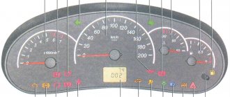
Every car has a dashboard where the main instruments of the vehicle are located. Thanks to the tidy, the driver knows at what speed he is traveling, what equipment is turned on and what is the condition of the main components of the car. In this material, we invite you to find out what the Lada Granta instrument panel is, what indicators are installed on it and what malfunctions you may encounter in its operation.
Content
[ To uncover]
[Hide]
Description and location of indicators and instruments on the panel
Designation of indicators on the dashboard
First, let's look at the description; the Lada Granta instrument cluster, the diagram of which is shown above, includes the following components:
- Tachometer, this sensor allows you to find out what the crankshaft rotation speed is at the moment.
- Indicator of malfunctions in the operation of the internal combustion engine control system.
- Left turn signal.
- Engine fluid pressure sensor. If it lights up after starting the engine, you need to check the oil level in the unit; if it is too low, there may be a leakage problem.
- Anti-lock braking system indicator.
- Light bulb of the standard anti-theft system - immobilizer. This unit is designed to block the engine from starting in the event of unauthorized entry into the car.
- The antifreeze overheating indicator in the cooling system appears if the engine temperature reaches 115 degrees.
- A light that turns on if the control unit has detected an emergency condition of the brake system. As a rule, its appearance is due to a lack of brake fluid in the reservoir.
- Right turn signal.
- Low battery indicator.
- Speedometer, the needle of which corresponds to the speed limit at which the car is moving. The speed sensor, which displays this information on a scale, is mounted on the gearbox housing.
- Indicator for turning on the exchange rate control system.
- Upshift prohibition lamp (as a rule, not used).
- This indicator appears when the high beams are activated.
- Symbol for turning on the rear fog lights.
- Lamp for low beam lighting.
- Front fog light activation indicator.
- A button designed to reset the daily mileage.
- LCD screen that displays data about the last trip, in particular, mileage. Depending on the vehicle configuration, the data displayed on the screen may differ. In general, the display can display time, mileage, outside air temperature, on-board computer options, fuel volume, as well as information in the form of hints regarding gear shifting.
- Indicator of unlocked doors in the car.
- Symbol of reserve fuel remaining in the tank.
- This indicator appears when the tire pressure is insufficient.
- Signal lamp for EUR operation. If it lights up when the engine is running, then most likely there are problems with the electric power steering system.
- This symbol illuminates when the seat belts are not fastened.
- Engine fault indicator, in most cases not used.
- Airbag status symbol. It always appears after turning on the ignition, since the system is in testing mode. If it continues to light after starting the power unit, this may indicate a problem with the system, so you need to contact service. If this indicator is on, then in the event of an accident the airbag either will not deploy, or it may deploy at the wrong moment while driving, which could be even worse (author - Lada Granta Fan channel).
Possible faults
If everything is clear with the description, then let’s move on to the malfunctions. Like any other electronic component, the Lada Granta instrument panel is also susceptible to various malfunctions.
What kind of breakdowns can occur in the operation of the control panel:
- The tidy is broken. If the shield fails, there can be quite a lot of symptoms. For example, only some or all of the devices will refuse to work. If this is the case, then the problem in this case may lie either in the power supply of the device or in its board. It is better to entrust repair problems to specialists.
- The tidy is glitchy. For example, all doors are closed and the unlocked door indicator is on, or the optics are not turned on, but the corresponding light on the dashboard is flashing. As a rule, in this case the problem lies precisely in the board (of course, if the sensors are working). If the problem is in the board, then flashing the dashboard firmware can solve it, but this option does not always help. It is possible that the electrical equipment lights are on on the dashboard due to a faulty sensor, so it would be a good idea to check its functionality.
- All devices work, but there is no backlight. If all the backlight bulbs do not work at once, then most likely the problem lies in a blown fuse or a damaged wire or connector. Checking the wiring is done using a multimeter.
- Only part of the light bulbs or one of them does not work. In this case, the malfunction consists of a burnt-out lamp; to eliminate it, the instrument panel in the Lada Granta is dismantled, after which the burnt-out lamps in it are replaced.
- The equipment indicator on the dashboard does not turn on. For example, you turn on the high beams, but the corresponding light does not light up. This may be due either to a failure of the indicator itself (the lamp is changed in the same way), or to a breakdown of the sensor. It is quite possible that there is poor contact between the light bulb and the wiring.
- Speedometer failure. The cause of the malfunction may lie in the board or speed sensor installed on the device. The situation is similar with sensors - fuel level, engine temperature. If they do not work or show incorrect values, then the problem should be looked for in the controllers themselves, wiring or board. It is possible that the devices are not working simply due to poor contact.
Dismantling instructions
To dismantle the device, you must follow the instructions:
- First remove the cover of the fuse box located to the left of the steering wheel.
- Unscrew the three bolts securing the plastic lining of the control panel.
- Dismantle the lining itself, and then unscrew four more bolts of the tidy. Pull it towards you.
- Next, squeeze the connector with the wires and disconnect it from the control panel.
- Dismantle the unit and repair or replace it. Assembly is carried out in reverse order.