February 28, 2017 Lada.Online 28 592 0
The starter is removed in connection with its replacement, inspection or repair. On LADA cars, the starter is installed on the clutch housing at the front in the direction of travel. Before starting work, you should disconnect the negative terminal of the battery, drive the car onto an inspection ditch (overpass) and remove the engine protection.
On all modern LADA cars (Lada XRAY, Vesta, Largus, Granta, Kalina, Priora and Niva 4x4), removing the starter is performed in the same way. Installation is carried out in reverse order. Distinctive features of the process are presented below.
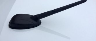
Fuse box Lada Vesta
Mounting block Lada Vesta fuse diagram
Interior mounting block Schematic location of fuses Body connector Layout of buttons on the steering wheel
Lada Vesta is equipped with many electrical appliances, each of which is vulnerable to voltage surges. To protect consumers, there is a fuse in the circuit of each of them, and if for some reason it blows, it will have to be replaced, otherwise the electrical appliance will not work. Just first you need to find the Lada Vesta fuse box.
Why are fuses needed?
Fuses are elements of an electrical circuit that protect devices from voltage surges. They consist of a plastic case, two contacts and a working element.
The principle of their operation is simple: each element has an operating voltage, and if this value is exceeded, it will immediately burn out and the circuit will open. In fact, the protective component takes the blow, protecting electrical appliances from damage. Its purchase is much cheaper than replacing one or more consumers, which, among other things, can affect the control of the car.
Interesting!
The cigarette lighter in Lada Vesta has a fuse that blows more often than others. Usually the reason for this is connecting devices with high current consumption or several devices at once through a tee.
Lada Vesta fuse box with description (engine compartment
The required box is located above the battery, on the right side of the air filter. On the cover of the unit you can see warning signs in the form of a crossed out figure of a man with a hose and a lightning bolt.
To remove the cover, bend the two latches at the top and bottom. Be careful because... they are very fragile.
Schematic layout
The contents of this mounting block are as follows:
Mounting block
The current limit (amps) is indicated on each component. The Lada Vesta fuse diagram under the hood looks like this:
Lada Vesta fuse diagram
Which circuit each fuse belongs to and which consumer it is responsible for can be found in the table below.
Fuse Circuit Chart Fuse Chart Note: Depending on the configuration, some items may be missing.
Table with the designations of the relays that are present in the engine compartment block:
Relay designation table
Lada Vesta fuse box with description (interior)
This mounting block is located in a place familiar to drivers - near the left foot. Actually, the space around the trunk opening button and the headlight adjustment control is the cover of the mounting block.
First, remove the plastic clips (nails) that secure the cover to the upholstery. One of them is located on the side of the ignition switch, the other is in the lower left part of the cover (may be absent on some cars). Next, turn the 3 plastic handles at the bottom and pull the lid, releasing all the holders.
Schematic layout
In the interior mounting block you will see the following picture:
Interior mounting block
On a note!
In the lower right corner there are spare fuses for the Lada Vesta.
Schematically the block looks like this:
Schematic location of the fuses It is deciphered as follows: Decoding of the spare fuses Decoding of the spare fuses Decoding of the spare fuses Decoding of the spare fuses Decoding of the spare fuses Relays that are present in the cabin: Identification of the snout in the cabin Body connector Layout of the buttons on the steering wheel
Source: https://vesta-site.ru/kak-snyat-kryshku-predoxranitelej-na-lada-vesta-lada-vesta/
Payment via Portmone
After selecting payment through Portmone, the payment system will launch, where you need to select the payment method: bank card or Portmone account.
The price in the Portmone payment system is converted into dollars at the exchange rate of the Central Bank of the country where you are located.
If you have a bank card in a currency other than the dollar, then the money will be debited from the card at the rate of the Central Bank of your country at the time of the purchase.
After specifying payment details and confirming payment, payment for the goods will occur.
Starter - removal / installation
- LADA VESTA. Starter - removal / installation
- Removal
- Place the car on a two-post lift (electro-hydraulic lift type P-3.2 G with a lifting capacity of 3.2 tons).
- Turn off the ignition, lift the hood, disconnect the earth wire terminal from the battery (spanner 10).
- Raise the car to a height convenient for doing the work.
Remove the engine splash guard in accordance with the requirements of TI 3100.25100.20582.
For vehicles with manual transmission
Unscrew the two bolts 1, Figure 3-1, fastenings, remove the clutch hydraulic drive cylinder 2 without disconnecting the hydraulic drive tube 3, and hang the cylinder on the service hook (replaceable head 13, ratchet wrench, service hook).
- Figure 3-1 — Clutch hydraulic cylinder:
- 1 - bolt;
- 2 — clutch hydraulic cylinder;
- 3 — clutch hydraulic tube;
- 4 — bracket for fastening the clutch hydraulic cylinder;
- 5 — gearbox;
- 6 — clutch release fork
- For cars of all trim levels
- Figure 3-2 — Connection of the terminal and block of the wiring harness with the starter:
- 1 - nut;
- 2 — terminal of the front wiring harness to the starter;
- 3 — block of the front wiring harness to the starter;
- 4 - starter
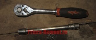
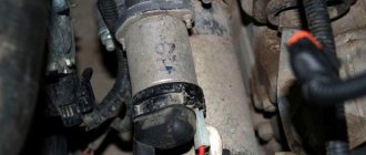
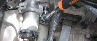
- Unscrew nut 1, Figure 3-2, and disconnect terminal 2 and block 3 of the wiring harness from the starter traction relay 4 (replaceable head 13, extension cord, ratchet wrench).
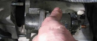
- Unscrew three bolts 1, Figure 3-3, remove bracket 2 for fastening the hydraulic clutch cylinder (for vehicles with a manual transmission) and starter 3 (replaceable Torx E10 head, extension, ratchet wrench).
Electrical breakdowns
We inspect the section of electrical wiring from the steering column of the passenger compartment to the starter in the engine compartment. Signs:
- Insufficient, weak rotation of the rotor;
- The control unit does not respond when current is applied;
- The starter clicks but does not turn.
- Sign of an interturn short circuit, broken wiring, faulty solenoid relay;
- Wear of armature, brushes.
At the same time, we check the integrity of the electrical wiring in the area from the steering column to the starter. We exclude damage, breaks, weak contact.
We measure the battery charge. When the level is below 12.0 V, we recharge. Also, we inspect the condition of the ignition switch, eliminating play, insufficient contact, and jamming.
Carrying out comprehensive diagnostics will eliminate third-party breakdowns not related to the operation of the Lada Vesta starter.
How to remove the starter on LADA cars with your own hands - Vestashop77
_x000D_
The starter is removed in connection with its replacement, inspection or repair. On LADA cars, the starter is installed on the clutch housing at the front in the direction of travel. Before starting work, you should disconnect the negative terminal of the battery, drive the car onto an inspection ditch (overpass) and remove the engine protection.
_x000D_
On all modern LADA cars (Lada XRAY, Vesta, Largus, Granta, Kalina, Priora and Niva 4x4), removing the starter is performed in the same way. Installation is carried out in reverse order. Distinctive features of the process are presented below.
_x000D_
Lada XRAY and Vesta
_x000D_
Remove the engine splash guard (instructions for Lada Vesta, XRAY).
_x000D_
For configurations with manual transmission: Unscrew 2 bolts (No. 1) and remove the clutch hydraulic cylinder (No. 2), without disconnecting it from the hydraulic actuator tube (No. 3). Hang the cylinder on the technological hook (head “13”).
_x000D_ _x000D_
For all configurations: Unscrew the nut (No. 1) and disconnect the terminal (No. 2) and the block with wires (No. 3) from the starter traction (retractor) relay (No. 4) (head “13”).
_x000D_ _x000D_
Remove 3 bolts (No. 1), remove the clutch hydraulic cylinder mounting bracket (No. 2) (for vehicles with manual transmission) and the starter (No. 3) (Torx E10).
_x000D_ _x000D_
Lada Largus
_x000D_
Remove the cover (if equipped) of the electronic control unit (ECM) by releasing the two fasteners (flat-head screwdriver). Unscrew the 2 nuts (No. 1) securing the expansion tank (No. 2) (10mm wrench). Remove and move the expansion tank to the side without disconnecting the hoses.
_x000D_ _x000D_
For configurations with JR5 gearbox:
_x000D_
- _x000D_
- disconnect the hinges (No. 1) of the gear selection and shift cables from the gearbox (flat-head screwdriver);
- press the clamps on both sides and disconnect the stoppers of the sheaths of the selection and shift cables from the gearbox bracket.
_x000D_
_x000D_
_x000D_ _x000D_
For configurations with JH3 gearbox:
_x000D_
- _x000D_
- remove the cover (No. 1) of the gearshift drive rod joint;
- Unscrew the bolt (No. 2) securing the gear shift rod, remove the spacer sleeve and disconnect the rod (10mm wrench).
_x000D_
_x000D_
_x000D_ _x000D_
Unscrew the 3 bolts (No. 1) securing the starter (head “13”).
_x000D_ _x000D_
Raise the car and unscrew the nut (No. 2) securing the bracket (No. 4) to the intake manifold (No. 3) (head “13”). Unscrew the bolt (No. 6) securing the bracket (No. 4) to the cylinder block (No. 5) (head “17”). Remove the bracket (No. 4) that mounts the intake manifold (No. 3).
_x000D_ _x000D_
Unscrew the nut (No. 2), Figure 3-7, and disconnect the harness (No. 1), Figure 3-6, of the ignition system wires from the starter (No. 3) (head “10”).
_x000D_ _x000D_
Unscrew the nut (No. 4), Figure 3-7, securing the starter wire (No. 5) ("10" head). Disconnect the starter wire. Unscrew the nut (No. 3) securing the starter electromagnetic relay wire (No. 5) (head “8”). Remove the starter.
_x000D_
- The process is also shown in the video:
_x000D_ _x000D_ _x000D_
Lada Granta, Kalina, Priora
_x000D_
Remove the protective cap (No. 3), unscrew the nut securing the wire to the starter solenoid relay (No. 4) and disconnect the wire from the relay (head “13”). Disconnect the block with wires (No. 2) from the starter solenoid relay.
_x000D_
- For cars with a manual transmission with a traction drive: unscrew the 3 nuts securing the starter (No. 5) and remove it (head “13”).
- For cars with automatic transmission and manual transmission with cable drive: unscrew three bolts (No. 5) and remove the starter (No. 3) (head “13” or Torx E14).
- Process video:
_x000D_ _x000D_ _x000D_ _x000D_ _x000D_ _x000D_
Lada 4×4
_x000D_
- Remove the rear support bracket for the intake pipe by unscrewing the two bolts with a 13mm wrench.
- We remove the starter protective shield by unscrewing its fastening nuts with a “13” wrench.
- Removing the starter protective shield on the Niva 4x4Removing the starter protective shield on the Niva 4x4Removing the starter protective shield on the Niva 4x4
_x000D_ _x000D_ _x000D_ _x000D_
From the bottom of the car, unscrew the two bolts securing the starter.
From the engine compartment side, move the starter forward and disconnect the block with wires.
_x000D_
From the bottom of the car, unscrew the two bolts securing the starter on the Niva 4x4, remove the starter wire on the Niva 4x4
_x000D_
We unscrew the nut and disconnect the wire tip from the contact bolt of the traction relay. Remove the starter from the engine compartment.
_x000D_
- removing the starter on a Niva 4x4; removing the starter on a Niva 4x4; removing the starter on a Niva 4x4
- Video instruction:
- By the way, do you know that the ignition system of LADA cars can be improved, for example, by abandoning the ignition key in favor of a start/stop button.
_x000D_ _x000D_ _x000D_
Source: https://vestashop77.ru/kopilka-znanij-lada-vesta/remont-svoimi-rukami/kak_snyat_starter_na_avtomobilyah_lada_svoimi_rukami
Payment via PayPal
After selecting payment via PayPal, the PayPal payment system will launch, where you need to select the payment method: bank card or PayPal account.
If you already have a PayPal account, then you need to log into it and make a payment.
If you do not have a PayPal account and you want to pay using a bank card via PayPal, you need to click on the “Create an Account” button - shown with an arrow in the picture.
PayPal will then prompt you to select your country and provide your credit card information.
After specifying the information required to make the payment, you must click on the “Pay Now” button.
Removing and installing the starter of a Lada Vesta car
- We install the car on a lift or inspection ditch.
- Disconnect the negative terminal of the battery.
- Remove the engine crankcase protection.
- If your car has a manual transmission:
- Using a 13 socket, unscrew the two bolts 1, Figure 1, fastenings, remove the clutch hydraulic drive cylinder 2 without disconnecting the hydraulic drive tube 3, and hang the cylinder on the service hook.
- For cars of all trim levels
- Using a socket 13, unscrew nut 1, Figure 2, and disconnect terminal 2 and block 3 of the wiring harness from the starter traction relay 4.
- Unscrew three bolts 1, Figure 3, remove bracket 2 for fastening the hydraulic clutch cylinder (for vehicles with a manual transmission) and starter 3 (use: replaceable Torx E10 head, extension, ratchet wrench).
- Installation
- For cars of all trim levels
- Install starter 3, Figure 3, bracket 2 for fastening the hydraulic drive cylinder (for vehicles with a manual transmission) and secure it with three bolts 1.
Bolt tightening torque 18…24 Nm (1.8…2.4 kgf.m) (Used: replaceable Torx E10 head, extension, ratchet wrench, torque wrench).
For vehicles with manual transmission
Install cylinder 2, Figure 1, of the hydraulic clutch and secure with two bolts 1.
The tightening torque of the bolts is 13…20 Nm (1.3…2.0 kgf.m) (replaceable head 13, ratchet wrench, torque wrench).
Connect starter traction relay 4, Figure 2, terminal 2 and block 3 of the wiring harness.
The tightening torque of nut 1 securing the wiring harness terminal to the starter traction relay is 18…24 Nm (1.8…2.4 kgf.m) (replaceable head 13, extension, ratchet wrench, torque wrench).
Install engine protection.
Connect the earth wire terminal to the battery.
Source: https://autoruk.ru/marka-avto2/vesta/elektrika-vesta/kak-snyat-starter-avtomobilya-lada-vesta
Payment via WebMoney
After selecting payment via WebMoney, the payment system will launch, where you need to select the payment method: bank card or WebMoney wallet.
If you already have a WebMoney wallet, then you need to log into it and make a payment.
If you do not have a WebMoney wallet and you want to pay in another way, you need to select any of the methods that WebMoney offers and make the payment
After specifying payment details and confirming payment, payment for the goods will occur.
Self-replacement of the starter for Lada Vesta and X-Ray
The process of replacing the starter on Lada Vesta and X-Ray yourself is quite simple and does not require special knowledge or tools. In addition, the dismantling of this unit is carried out not only in connection with the installation of a new one, but also in the process of replacing the timing belt, etc. Therefore, it is worth understanding the situation.
The component itself is located in front of the clutch housing.
Dismantling
- Before starting work, you need to drive the car onto an overpass or pit, and then remove the “-” terminal from the battery.
- It is also necessary to dismantle the engine protection - on the Lada Vesta it is secured with 13 bolts, to unscrew which a 10mm wrench is used.
- On the Lada X-Ray, the same 10mm wrench is used for operation, but there are not 13 bolts on the engine mudguard, but only 6.
- Further, the algorithm for self-replacement of the Lada Vesta and X-Ray starter directly depends on the modification of the car.
- Versions with manual transmission.
First you need to unscrew the 2 mounting bolts marked in Figure No. 1, and then remove the clutch hydraulic cylinder, which is No. 2. In this case, there is no need to disconnect the clutch hydraulic tube (under No. 3).
In the end, all that remains is to hook the cylinder to the technical hook.
- Regardless of the configuration.
- First, the nut marked No. 1 is unscrewed, after which the block with wiring indicated No. 3 and the terminal (under No. 2) are disconnected from the starter traction relay (under No. 4).
- Next, unscrew the 3 bolts indicated as No. 1, dismantle the hydraulic clutch cylinder retainer bracket, which is marked No. 2 (only for versions with a manual transmission), and also, using a Torx E10 bit, remove the starter.
- Installation of a new component and assembly are carried out in reverse order.
- This completes the independent replacement of the starter for Lada Vesta and X-Ray.
Where can I buy?
You can buy a starter for Lada Vesta and X-Ray both in a car store and online. The table shows the most popular sites.
| Manufacturer/site | vendor code | Price, rub.) |
| VALEO | n11645 | 5985 |
| VALEO | CB-00034377 | 6590 |
| https://21cristal.ru/p296251087-starter-dlya-avtomobilya.html | TS12E902 | 4148 |
| https://www.autoopt.ru/catalog/476366-starter_lada_vesta_dv_h4m_oe/ | 476366 (for N4M series engine) | 9800 |
| VALEO | 9500 | |
| StartVOLT | LST0190 | 3848 |
| FENOX | ST31172C3 | 2705 |
| SAT | ST23300BC20B | 4430 |
| SOATE | TS12E901 | 3981 |
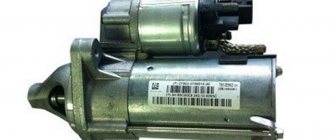
The Lada Vesta and X-Ray come with a starter from the VALEO company from the factory, and therefore it is recommended to buy just such a component, even though it is more expensive than its analogues.
Source: https://club-vesta.ru/ustrojstvo/samostoyatelnaya-zamena-startera-na-lada-vesta-i-iks-rej
Payment via Yandex Cashier
After selecting payment via Yandex, the Yandex Cashier payment system will launch, where you need to select a convenient payment method (bank card, QIWI, Yandex Money account, etc.)
After specifying payment details and confirming payment, payment for the goods will occur.
If you have a bank card in a currency other than the ruble, then the money will be debited from the card at the rate of the Central Bank of Russia at the time of the purchase.
This payment method is optimal for residents of Russia, Kazakhstan and Belarus.
Lada Vesta starter: device, replacement, how it is installed and principle of operation
The starter is the main unit of the engine starting system. The unit spins the engine crankshaft to the frequency required to start the engine. The starter is powered by a battery. We will tell you in more detail about the design of the Lada Vesta starter at the end of the article.
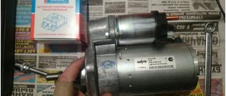
What kind of starter for Lada Vesta
The Lada Vesta has an electric starter from Valeo. Its cost in stores is between 4,000 and 6,000 rubles. At official service stations, replacement will cost approximately 1,000 - 2,000 rubles.
Starter malfunctions Lada Vesta
To start the Lada Vesta engine, it is necessary for the air-fuel mixture to appear in the cylinders, as well as to ignite it using an electric spark. To do this, the engine must already be spun up to a certain speed using an electric starter. Problems with starting the engine most often arise due to a malfunction of one or another element of the vehicle's systems.
Replacing the Lada Vesta starter
Removing and installing the starter of a Lada Vesta car.
We install the car on a lift or inspection ditch. After which we carry out preparatory work: remove the engine crankcase protection and disconnect the negative terminal of the battery.
If your car has a manual transmission
- bolt;
- clutch hydraulic cylinder:
- clutch hydraulic tube;
- bracket for fastening the hydraulic clutch cylinder;
- Transmission;
- clutch release fork
It is necessary to unscrew the two bolts (item 1, Fig. 1) with the head “13”, remove the clutch hydraulic cylinder (item 2) and hang the cylinder on the service hook. In this case, there is no need to disconnect the hydraulic drive tubes (item 3)
For cars of all trim levels
- screw;
- front wiring harness terminal to starter;
- front wiring harness block to starter;
- starter
It is necessary to unscrew the nut (pos. 1, Fig. 2) with a head on “13” and disconnect the starter (pos. 2) and the wiring harness block (pos. 3) from the traction relay.
- bolt;
- bracket for fastening the hydraulic clutch cylinder;
- starter
We unscrew the three bolts (item 1, fig. 3), remove the clutch hydraulic cylinder mounting bracket (item 2) (for cars with manual transmission) and the starter (item 3). To perform these operations you will need a ratchet wrench, an extension and a replacement Torx E10 socket.
Installing a starter on Lada Vesta
For cars of all trim levels
We mount the starter (item 3, Fig. 3) and the hydraulic drive cylinder mounting bracket (item 2) (for cars with a manual transmission), secure it with three bolts (item 1). The tightening torque of the bolts should be 18…24 Nm (1.8…2.4 kgf.m). To perform these operations you will need: a ratchet wrench, an extension, a replacement Torx E10 socket and a torque wrench.
For vehicles with manual transmission
We install the clutch hydraulic cylinder (item 2, Fig. 1), secure it with two bolts (item 1). The tightening torque of the bolts should be 13...20 Nm (1.3...2.0 kgf.m), to perform the operation you will need a tool: a replaceable head for “13”, a torque wrench and a ratchet wrench.
To the starter traction relay (item 4, Fig. 2) we connect the terminal (item 2) and the wiring harness block (item 3). Tighten the nut (item 1) with a tightening torque of 18…24 Nm (1.8…2.4 kgf.m)
After this, install the engine protection and connect the ground wire terminal to the battery.
Electric starter device Lada Vesta
The principle of operation of a car starter is the same on all cars. Different starters have slight design differences, but once you understand the design of the starter, it will not be difficult for you to understand the features of another starter.
Each car starter has from 40 to 60 parts, but in the end there are only three main components:
- Electric DC motor;
- Traction (pull-in) relay;
- Bendix.
The main unit is the electric motor, which rotates the crankshaft of the car engine through gears. Bendix and solenoid relays are auxiliary devices.
The retractor relay on the Lada Vesta, as on other cars, performs two functions at once:
- Moving the bendix lever with the working gear;
- Closing the contacts of the electric motor after the gear and flywheel ring are engaged.
Bendix got its name from the American inventor Vincent Bendix, who created this unit. The purpose of the bendix is to provide a temporary connection between the starter shaft and the flywheel crown to rotate the engine crankshaft.
The principle of operation of the Lada Vesta starter
A starter is an electric motor that is powered by a vehicle's battery and serves to start the internal combustion engine. When you turn the ignition key in a car, the following processes occur:
- The ignition switch contacts close and send current through the starter relay to the pull-in coil of the traction relay;
- The solenoid relay moves inside the housing and pushes the bendix out of the housing, causing the gear to engage with the flywheel;
- When the armature of the retractor relay reaches the end point, the contacts close and the current flows to the holding winding of the relay and the winding of the starter motor;
- The engine spins up and starts. As soon as the flywheel rotation speed exceeds the starter shaft rotation speed, Bendix disconnects the starter gear and the flywheel using a return spring;
- When the ignition key is returned to the first position, the supply of electric current to the starter is stopped.
Despite its apparent complexity, the electric starter in the Lada Vesta is a fairly simple mechanism.
Source: https://new-vesta.ru/lada-vesta-starter/
Mechanical problems
The immobility of the crankshaft with an active starting device is the first sign of failure of the clutch, pressure spring, flywheel teeth, and retaining ring.
Also, problems in the power supply system will be indicated by a metallic grinding noise that accompanies the operation of the control unit. An equally frequent breakdown is the continuation of rotation of the launcher after starting the engine. The pressure spring, drive shaft, and contact plate are subject to mandatory inspection. And also, a retractor relay, a support bearing.
The cause of unstable operation may be third-party mechanical damage, the negative consequences of an accident, impact, or collision. Take these factors into account as well.
Generator repair
The price of a new Lada Vesta generator is very high. Therefore, in case of some breakdowns, it is more advisable to repair the unit rather than replace it. Restoring functionality usually begins by removing the power source from the vehicle.
Dismantled generator
For electrical problems, it is recommended to use a multimeter. Using a continuity test, you should make sure that there is no winding breakage, breakdown to the housing, or interturn short circuit.
Testing with a multimeter
Most often problems arise due to abrasion of the brushes. Replacing them allows you to restore reliable electrical contact.
Brushes
Abrasion of slip rings usually occurs during long-term operation of the generator.
Slip rings
How to check the ignition coil of a VAZ
If the ignition coil is faulty, the engine will not start. A characteristic sign of a faulty coil is its increased temperature when the ignition is turned off. This is easy to determine by touch.
Signs of a faulty ignition module may include the following:
- hesitant engine starting or failure to start;
- failures during sudden changes in speed;
- high fuel consumption;
- two cylinders do not work, the engine is feverish;
- lack of dynamics;
- a sharp drop in power;
- drop in power and thrust after warming up.
These symptoms may not only be caused by the ignition module. To determine the malfunction, it is enough to spend a few minutes diagnosing spark plugs, high-voltage wires and caps. This will eliminate the remaining elements of the ignition system and make sure that it is the ignition module that is faulty.
Checking the ignition coil is performed in one of 2 ways. The simplest one is to remove the central wire from the breaker-distributor, bring it to the motor housing and turn it with the starter, and a running spark should appear. After this, we check the energy supply to a separate spark plug, for which we unscrew the working spark plug, bring its contact to ground and attempt to start the engine. In this case, the spark should come from the wire to ground. If it is absent, the reason will be a malfunction of a system element such as the ignition coil.
To check the module in the second way, we only need a multimeter, then follow the step-by-step instructions:
- We check the power supply and the presence of pulses supplied from the ECU. We check the power between the central terminal (15) of the wire block connected to the module and the engine ground. When the ignition is on, the voltage should not be less than 12 V. Otherwise, either the battery is dead or the ECU does not work.
- We check the pulses from the ECU on the wiring block. We install one tester probe on connector 15, the second on the far right, then on the far left. The assistant cranks the engine with the starter, and at this time we record short-term voltage surges with a tester. If there are no impulses from the ECU, it is he who is to blame.
- We check the resistance on the secondary windings of the coils. We put the tester in resistance measurement mode and measure it at the high-voltage terminals of the module cover. Between pins 1 and 4 and pins 2-3, the resistance should be 5.4 kOhm. Otherwise, the module must be replaced.
- We check the resistance of the primary windings between contacts 15 and the rightmost, then the leftmost terminals. Nominal - 0.5 Ohm. Deviation is not allowed.
- Check the module for a short circuit. In ohmmeter mode, install one multimeter probe on the central terminal, the second on the metal body. There shouldn't be any resistance. If the device detects at least some resistance (other than unity or infinity), the module must be replaced.